Volume & Surface Coils for Low- & High-Field MR
Ed Boskamp1
1Hyperfine, Guilford, CT, United States
1Hyperfine, Guilford, CT, United States
Synopsis
Keywords: Physics & Engineering: Hardware
Motivation: This course is intended for engineers and physicists who want to design RF coils
Goal(s): After this course you will be able to make simple transmit and receive coils for low and high field
Approach: We will review design requirements for low and high field Tx and Rx coils, SNR, SAR, EM field-tissue interaction, decoupling
Results: High field and low field require very different designs
Impact: Coil designers will appreciate the differences in low and high field RF coil designs and will understand the difference in design requirements
Introduction
When I started building RF coils for MRI in 1983 it was for the strong magnetic field of 0.3 T. In the 41 years that have passed I built a large number of coils and arrays between 0.064 and 9.3T. Each of these field strengths pose unique challenges to RF coil design. We will be addressing:- · The difference in requirements for Transmit and Receive coils
- · EM field and tissue interaction at UHF
- · SNR
- · Decoupling between Transmit and Receive coils
- · SAR
- · Ultra low field coil design and its challenges
Transmit (Tx) coil versus receiver (Rx) coil requirements
These coils have very different design requirements. During the RF transmit pulse we want to make sure we are creating a uniform flip angle distribution across the excitation volume, and we want to do it efficiently and without exceeding SAR limits and without creating image artifacts from areas where the gradient fields are non linear. This leads to the following requirements for Tx coils:- · The RF magnetic field in the imaging volume needs to be uniform but needs to drop off rapidly outside the imaging volume, defined by Magnetic field uniformity and gradient linearity.
- · All RF energy should be used towards the creation of a circularly polarized RF magnetic field without waste.
- · The input impedance of the Tx coil shall be equal to the characteristic impedance of the transmission line (coax cable) to prevent reflection of power at the input. This is typically 50 ohm and is achieved by impedance matching.
- · We shall not waste RF energy in the gradient coil, hence body size RF transmit coils are typically surrounded by an RF shield. Such a shield will keep the RF fields out of the gradient coil environment but will be transparent for the gradient pulses.
- · Capacitors in the resonant Tx coil shall be distributed so that we do not create large E fields.
- · The Q of the coil by itself should be increased until patient losses dominate the Q. In Ultra low field systems the Q of the Rx coil needs to be as high as possible, given other constraints.
- · Every Rx coil has a circuit board attached containing T/R switches, tuning and matching networks, varactor diodes, Low Noise amplifier (LNA) and so on. The dielectric losses in the circuit board need to be kept to a minimum. This can be achieved through layout and substrate choices.
- · The LNA should be low noise, and the amplification of that LNA should be high enough so that the Noise figure of that first stage dominates the NF of the entire receive chain.
- · The impedance of the Rx coil shall be matched to the impedance the LNA wants to be connected to for lowest Noise Figure performance.
- · The coil shall be as close to the anatomy of interest as possible and should be shaped like the anatomy.
RF Transmit field uniformity
The transmit field needs to be uniform and preferably circularly polarized (B1+). There are several ways to create circularly polarized fields, but the most popular is the birdcage resonator introduced by Hayes at all in 1985 (1). A typical birdcage RF current distribution is shown in Fig 1. Other types of circularly polarized coils are needed for scanners that have a vertical magnetic field. At low to medium fields i.e. 1.5T and below the uniformity of the RF magnetic field is not affected much by the patient tissue, but that all changes when the RF wavelength gets to be in the same order of magnitude as the patient size. In tissue the wavelength is shorter by 1/√ε in which ε is the permittivity of the tissue at the frequency of interest. The result of the short wavelength is that we get standing waves and non uniform images. The only way to improve this is to create more degrees of freedom in the transmit coil design like an array of transmit coils (Fig 2) each with independent control of amplitude and phase. Obviously such a system is not mainstream in today’s commercially available MRI systems. The higher the field strength, the more Tx channels we need to shim the RF field.RF transmit coil impedance matching
The RF power amplifier is connected to the transmit coil via a coaxial cable with a characteristic impedance of typically 50 ohms. To prevent reflections the cable needs to be terminated with its characteristic impedance, and thus the transmit coil needs to look like a 50 ohm real impedance. There are many good books on Impedance matching (2), so I am not going to spend any time on it here.SAR
SAR or specific absorption ratio is a byproduct of transmitted RF energy dissipated in human tissue. MRI's radio waves, especially at very high frequencies cause tissue heating. There are legal limits to how much energy can be dissipated in the patient’s tissue. The SAR is given by $$SAR=\sigma E^{2}/2\rho$$, in which σ is the conductivity of the tissue and ρ is the density of the tissue. E is the E field magnitude. The E field patterns are closely linked to where all the capacitors in the transmit coil are located. For example, a birdcage resonator can be high pass with all the capacitors in the endrings or low pass, with all the capacitors in the rungs. Both coils have the same RF current distribution and the same RF magnetic field but they have entirely different E field patterns. Lowest SAR is obtained by distributing the capacitance needed to resonate the coil. Lowest E fields are produced by a birdcage that has capacitors in both the rungs and the rings. It is called a bandpass birdcage.Receiver coil and array design
In fig 3 we see several Rx coil designs for different anatomies. Note that these coils are all small, and only big enough to cover the anatomy of interest. We can increase SNR over a large volume coil if we apply an array of small coils that covers the same volume, but then we must make sure that the noise between these array elements is not correlated or we will lose our SNR advantage. We can do this with the help of low input impedance LNAs as described in Roemer’s paper(3). We can increase the number of channels in the array leading to smaller individual coil elements but beyond a certain diameter the coil noise becomes dominant again so it is not worth the effort and cost. There are other reasons to go to large arrays, like acceleration using a method called Sense, but it is beyond the scope of this lecture.Decoupling
During the RF transmit pulse, the transmit coil generates a strong RF magnetic field that gets picked up by the receiver coil(s) and that induces a strong current in the receiver coil. The induced current destroys the uniformity of the transmit field, and can cause local component and patient heating. The way to prevent this is to put a switch in series with the receiver coil. The switch has to be low impedance or the Q of the receiver coil will suffer. It is usually done as a parallel resonator (tank) where the inductor is in series with a PIN diode or a GaN FET. During the data acquisition phase the Rx coil is resonant but since it couples to the large excitation coil, it picks up all the noise from the Tx coil (RFPA and patient). If we do not block the noise from the TX coil then the image SNR would suffer. We therefore put T/R switches in the Tx coil. They can be PIN diodes directly in the path of the resonator or as part of a tank. Currents in the large Tx coil as well as the voltages are high, so the components of the T/R switch need to be able to handle the stress. The switches in the Rx coil also see significant current during the Tx pulse. This is a concern, since this leads to a local temperature rise of the T/R switches, close to the patient. Array coils need to be decoupled in an additional way: They also need “soft” blocking between coil elements to prevent Array element coupling and coherent noise. Roemer’s paper (3) describes how to do this with low input impedance LNAs.Ultra low field
Recently ultra low field portable MRI scanners were introduced with magnetic fields significantly below 0.1T. At these larmor frequencies of < 3MHz, the coil noise is dominant. In this case it is extremely important to increase the Q of the coil to the maximum. We could do the following to improve Q:- · Increase the number of turns on the coil to increase the sensitivity. B1/I will increase, and since the Q is reactance / resistance, the Q will also increase. There is a limit to this however. Once the number of turns becomes so big that the individual windings are touching each other, then the proximity effect kicks in and this will affect the Q. Q is now affected by the losses due to interactions from the EM fields of one coil winding with its neighbor.
- · Reduce the coil resistance. 1.Theoretically we could increase the size of the conductor making up the coil windings. The skin effect pushes all the current to the circumference of the conductor, where it flows in a surface layer $$$\delta=\sqrt{(2\rho/\omega\mu)}$$$ called the skin depth, so a larger diameter conductor gives lower loss. In practice this does not work, because there are size constraints to the Rx coil. 2. Cool the coil: This will definitely help to cut down on coil loss, but is a huge engineering issue. We would have to cool the coil with liquid nitrogen, so we either blow super cooled gas over the coil or attach a dewar. Both are challenges with respect to patient safety and cost. In many cases the ULF system is also an economy system, so it is too expensive to go the cooling route. 3. Wind the coil out of Litz wire (4, 5). If the wire consists of large number of filaments, each with a diameter smaller than the skin depth, and the filaments are well insulated from each other, then the RF current density will spread out over all the filaments, greatly reducing resistivity.
Acknowledgements
No acknowledgement found.References
1. C E Hayes et al, An efficient highly homogeneous RF coil for whole body MRI at 1.5T, JMR 63,1985, p622 2. W.N. Caron, Antenna Impedance Matching, American Radio Relay League, 1989, ISBN 0872592200, 9780872592209 3. Roemer PB, Edelstein WA, Hayes CE, Souza SP, Mueller OM. The NMR phased array. Magn Reson Med. 1990 Nov;16(2):192-225. doi: 10.1002/mrm.1910160203. PMID: 2266841. 4. B. A. Reese and C. R. Sullivan, “Litz wire in the MHz range: Modeling and improved designs,” IEEE 18th Workshop on Control and Modeling for Power Electronics (COMPEL 2017), Stanford, CA, 2017 5. Y. Otomo, H. Igarashi, H. Sano and T. Yamada, "Analysis of Litz Wire Losses Using Homogenization-Based FEM," in IEEE Transactions on Magnetics, vol. 57, no. 8, pp. 1-9, Aug. 2021, Art no. 7402409, doi: 10.1109/TMAG.2021.3081819 6. D. I. Hoult. Fast recovery, high sensitivity NMR probe and preamplifier for low frequencies. Review of Scientific Instruments 50, 193 (1979)Figures
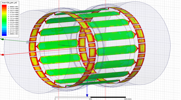
Fig 1: RF
current density distribution in a birdcage resonator
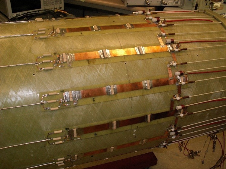
Fig 2: 16
channel transmit array
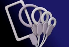
Fig 3: Various
Surface coils
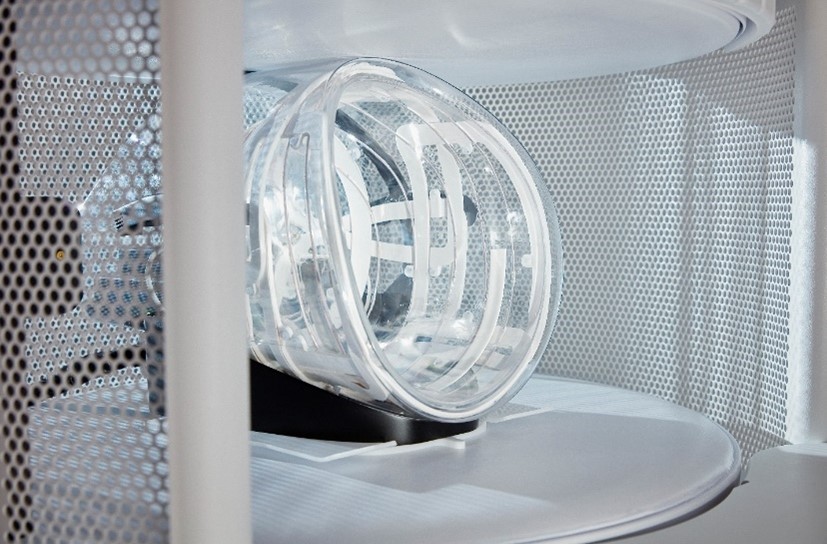
Fig 4: ULF
(ultra low field) Head coil, containing Tx coil and 8 channel Rx array