Shim Coil Design
1CEA Neurospin, France, 2MR Magnet Technology, Siemens Healthineers, Eynsham, United Kingdom
Synopsis
Keywords: Physics & Engineering: Hardware, Physics & Engineering: High-Field MRI, Neuro: Brain
We review methods to design shimming coils, starting from basic Spherical Harmonic coils to anatomy-driven multi-coil arrays. Assuming cylindrical surface geometries for the sought shim currents, we focus on a recent simple numerical method to find the stream function (SF) producing whatever target field. Applying this to brain B0 maps, we perform a SF principal component analysis and translate its main components into current lines gathered around SF extrema. We then segment coil windings into multi-channels to add flexibility in the shimming process. The same strategy can be applied to design shim arrays dedicated to other parts of the anatomy.Introduction
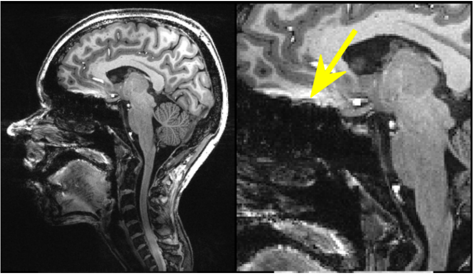
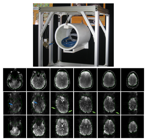
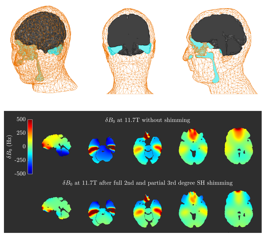
B0 shimming consists in homogenizing the static magnetic field in a region of interest (ROI), e.g. the human brain. As the B0 field strength increases, the disparities of magnetic susceptibilities between the diamagnetic biological tissue and the paramagnetic air contained in cavities like the lungs, inner ears or nasal sinus, cause a greater spread of B0 at the interfaces of exposed tissues (cf. Fig. 6). These translate into loss of spectrum resolution or image artefacts, such as distortions and signal dropout (due to intravoxel dephasing) in Echo-Planar images, or hypersignals in T1-weighted MP-RAGE images (e.g. Fig. 1). Thus we want to keep B0 as uniform as possible to minimize these artifacts. So shimming is required both at the main-magnet design stage, to correct for magnet manufacturing imperfections and reach B0 homogeneity in an empty sphere which will encompass the body under exam, and during examination to compensate for the above-mentioned unwanted gradients linked to the anatomy of the patient. Typically better-than-1ppm uniformity is required in the ROI, but magnet shimming and patient shimming are addressed separately: 1/ by passive shimming (with iron plates) or superconducting shim coils embedded in the helium vessel (sometimes referred as cold coils), 2/ by copper coils usually embedded in the gradient insert (warm coils). These sets of coils are usually designed to compensate for spherical harmonics (SH) of the B0 field spatial decomposition as they constitute a set of orthogonal solutions for the Laplace equation (ΔB0 = 0), which applies providing no magnetic source is present in the ROI. In this lecture, we will concentrate on the design of warm shim coils (however cold coil windings may be designed using some of the same methods). We will cover not only SH shim coil design, but also designs based on a particular anatomy (like the human brain), as these have recently proved to outperform the highest-order SH systems offered by manufacturers, at relatively low cost.Historical developments
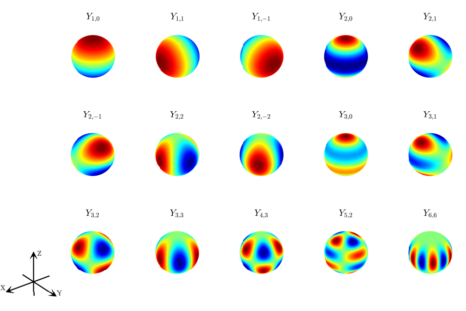
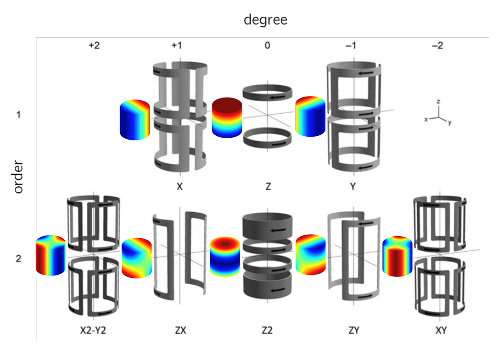
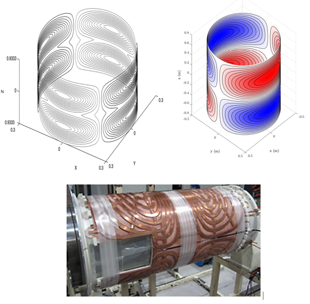
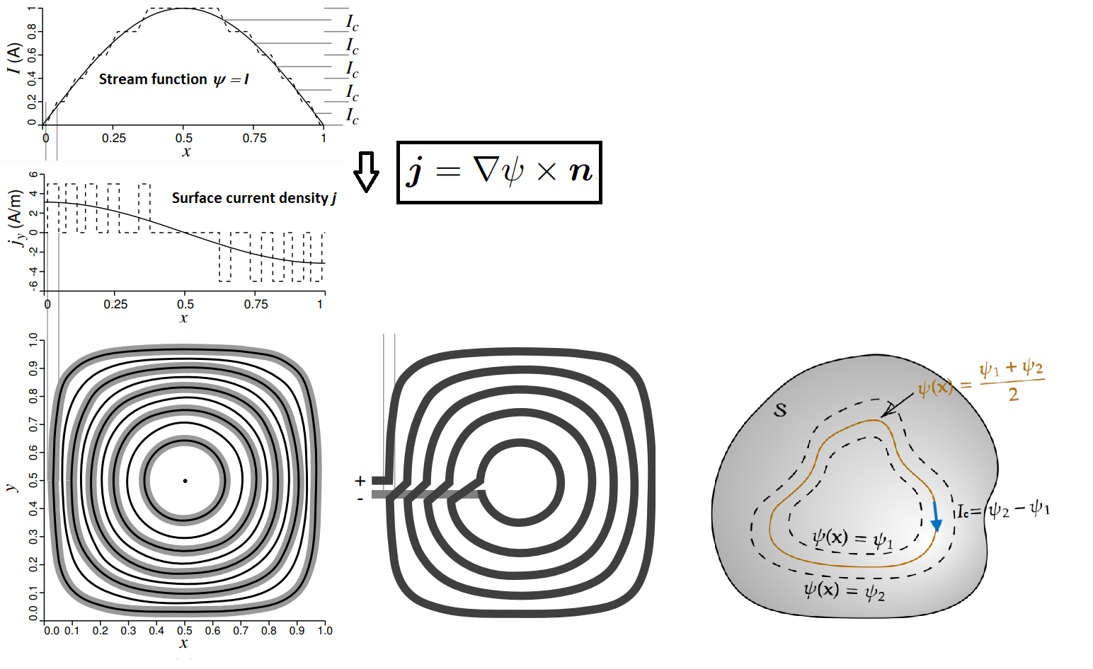
The Biot-Savart law yields the magnetic field spatial distribution generated by an arbitrary line of static current. We therefore need to solve an inverse problem: what current lines should we choose to compensate for some known initial non-uniform B0 distribution. Focusing first on low-order Spherical Harmonic compensation (cf. Fig. 2), we can start designing basic systems from circular loops or arcs of currents whose analytical solutions of the Biot-Savart law are known [Romeo 1984] (cf. Fig. 3). Then the Target Field Method (TFM) was introduced to solve the inverse problem analytically for infinite cylinder geometries using a Fourier-Bessel transform [Turner 1986]. It was later improved for finite length cylinders [Forbes 2001-03]. Then SH-based coils of general order and degrees could be found with a combined Target-Field and Stream-Function analytical approach [Brideson 2002] (cf. Fig. 4a).The stream function (SF), noted ψ, is a fundamental quantity for our problem solving and is related to surface current densities through the equation: j = ∇ψ × n, where n is the unit vector normal to the surface. ψ is easier to calculate and manipulate than j as it is a scalar value (rather than a 3D-vector) defined on the surface which will bear the surface currents (cf. simple 1D example in top plots of Fig. 9). For arbitrary target fields (other than SH components), numerical methods like the Inverse Boundary Element Method (IBEM) are more appropriate, leaving aside shim coil design based on analytical solutions. The IBEM presents itself as a more versatile technique, used in the most diverse kinds of coil former geometries due to its discretization of the domain into a triangular mesh. It solves the inverse problem by means of a stream function with regularization based on power dissipation and/or magnetic field energy. Despite its initial formulation [Pissanetzky 1992], only in 2003 a first rigorous mathematical treatment of IBEM appeared [Peeren 2003], and a subsequent practical implementation of a gradient coil designed with IBEM was shown in [Lemdiasov 2005]. The method was then applied for the design of various novel coils in [Poole 2007] (cf. bottom of Fig. 4), and has not ceased to gain interest since. The numerical problem formulation can take several design aspects into account, including resulting forces, torque, shielding. Different norms were studied as cost functions in [Poole 2010, Poole 2014]. Nowadays, IBEM has been implemented in an open-source MR coil layout generator, CoilGen [Amrein 2022]. Adaptations of the method also led to the Equivalent Magnetization Current method [Lopez 2009a, Lopez 2009b], where a magnetization is attributed to nodes in a triangular mesh and the inverse problem is set to compute the optimal magnetization generating some arbitrary target field. The magnetization is actually equivalent to the stream function and can be used to calculate the current density over the coil former and perform discretization into winding. Based on this idea, a simple numerical method was recently proposed for cylindrical current surfaces, the Dipole Boundary Method (DBM) [Pinho-Meneses 2020b], which will be developed next for ease of comprehension and implementation.
Stream function solving with the Dipole Boundary Method
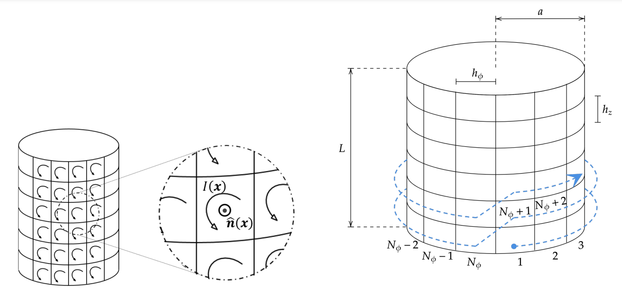
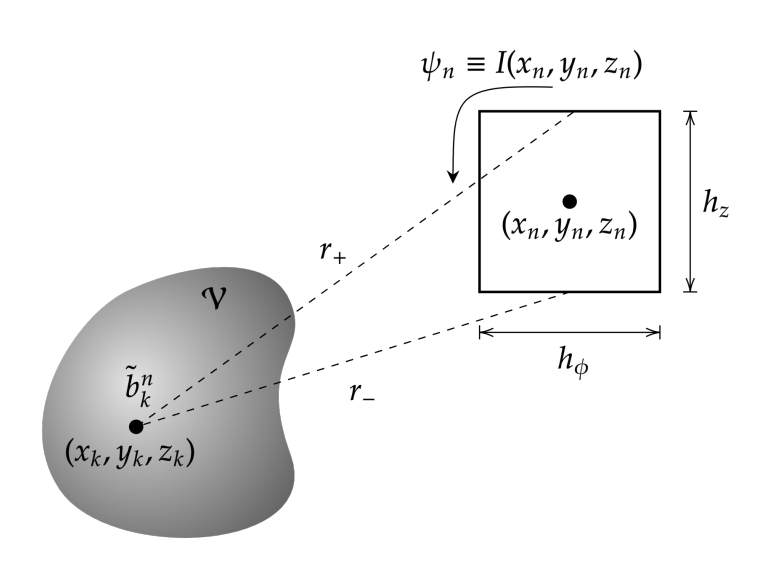
Suppose we target an arbitrary B0target distribution inside the ROI, which would typically be the opposite of a measured B0 map in the case of an anatomy-driven shim coil design (modulo a constant). In DBM, the cylindrical surface is split into Nc elementary square cells. Each cell can be considered a magnetic dipole with a circular current running along its edges (cf. Fig. 10). It was demonstrated this current is actually the stream function we are seeking [Pinho-Meneses 2020b]. From Biot-Savart, the Bz field generated by each cell can be calculated (geometry in Fig. 11) and expressed in vector/matrix form: b = C ψ, where b is the vector spanning all Bz-values in the Nv voxels composing the ROI, ψ is the Nc-vector of unknown stream-function values (or cell currents), and C is the Nv x Nc matrix easily determined from the geometry of each cell with respect to every voxel. As the number of voxels Nv largely dominates the number Nc of cells, this is an over-determined linear problem, which needs regularization to avoid excessive currents and power. Overall power can be expressed as the volume integral P = integral(|J|2/σ dv), where J is the current density in the cylindrical copper structure, and σ is its conductivity. This in turn can be written as a function of ψ as J = j/d = (∇ψ × n)/d where d is the copper surface thickness considered. Thus P can be formulated as the quadratic expression: P = ψT R ψ where the Nc x Nc resistance matrix R can simply be found from differential calculus. Eventually we seek ψ that minimizes the objective function var(B0target – C ψ) + λ ψT R ψ , where var() stands for the variance, and λ is the power-limiting regularization factor. This can be solved numerically via standard optimization solvers. Higher λ-values will limit power and the performance to reach the target field i.e. shimming. In fact, the full formalism is slightly more complex as boundary conditions need to fulfilled whereby no current should flow outwards or inwards of the cylinder from both ends, i.e. ψ should be kept constant on the cylinder boundaries. This can be expressed by the computation of a reduced vector ψ’, with ψ = Γ ψ’ where Γ is a simple matrix made of unit vector columns...From Stream function to winding
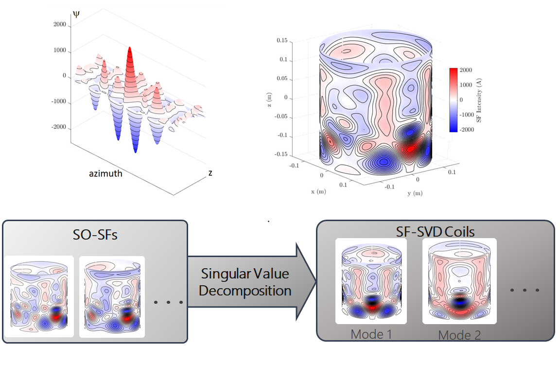
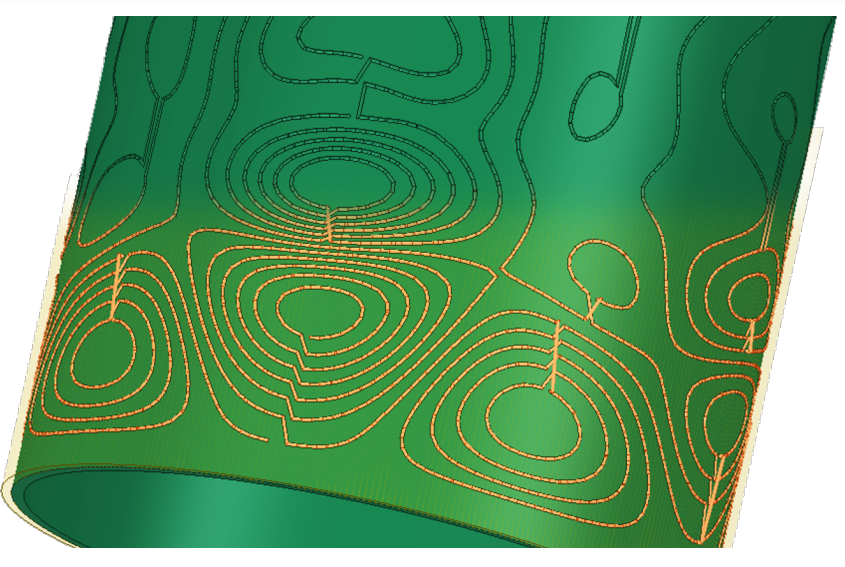
In order to transform the virtual stream function into concrete copper wire windings, the wire gauge should first be chosen based on the target maximum current to be sustained. In addition, a minimum distance δw between wires needs to be specified which will dictate the current Ic that needs to flow in all wires to generate the sought Bz distribution: Ic = δw max|∇ψ|. From a nominal current Ic, a family of isoheight curves of ψ representing the geometric centers of the coil wires can be obtained as detailed in [Peeren 2003] (cf. Fig. 9). Lower δw will yield many loops close to one-another in the winding with less current and more fidelity to the target Bz distribution. However this will also mean more wire length, resistance, inductance, and manufacturing complexity. Indeed since all loops segmented with this Ic-based discretization need to undergo the same current, they should presumably be put in series with junctions and bridges along z (which do not perturb Bz) between neighboring and distant coils (cf. bottom middle plot of Fig. 9).The DBM + winding method may be used for any target field, be it a particular SH order/degree compensation, or a B0-map characteristic of the ROI to be shimmed following low-order SH shimming. When applied to the B0 map of a human brain (e.g. in Fig. 6), the stream function ψ on the flattened cylinder looks like what is shown in Fig. 12a. Once δw is chosen, iso-Ic lines along the envelope of the SF plot represent close-to-ideal lines of currents needed to counteract the inhomogeneous B0-map inside the brain.
Coils optimized for the anatomy
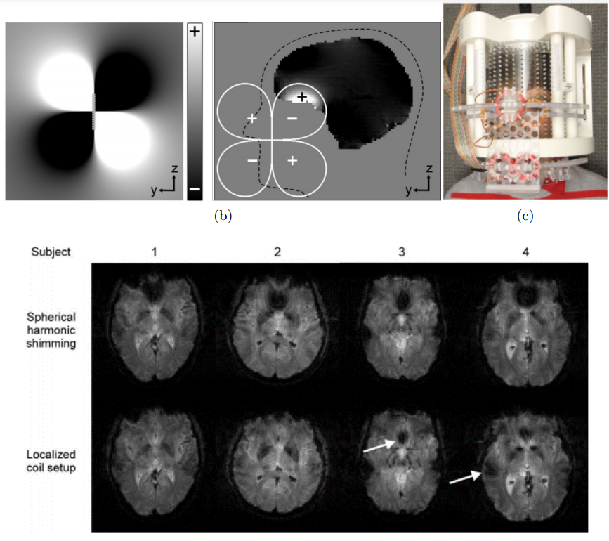
SH-coils generally need one layer of conductor per SH order and degree (sometimes more as active shield coils may be added to prevent eddy currents in the main magnet vessel). Since a system which integrates a full nth order needs (n+1)2-1 SH superimposed coils, the main MRI manufacturers may offer up to partial 3rd-order shimming for Ultra-High-Field magnets. A supplier has even gone up to 4th-order with two additional 5th-order shims [Hetherington 2021] (cf. Fig. 5 - this cylinder encompasses 18 coils presumably on 18 different layers).Nevertheless, such systems are heavy and not particularly optimized for the anatomy under scrutiny. This is why, for the past decade, efforts have been carried out to target the features of the human head anatomy more directly. First [Juchem 2010] proposed a set of 6 loops placed in front of the subject’s face to address the B0 inhomogeneities in the prefrontal cortex (Fig. 7). A bit later, the same authors proposed the first multi-coil array as a generalization of their primary 6-loop setup (cf. introduction of next section).
More recently, a couple of teams proposed more optimized anatomy-driven shim systems dedicated to the human brain [Pinho-Meneses 2020b, Jia 2020]. Such systems are based on collections of Ns brain B0 maps, typically a hundred. First a cylinder diameter is chosen between the RF coil and magnet bore as support for the shim wires. Proximity to the RF coil is sought to maximize shim performance for a given nominal current, or to minimize shim current for equivalent performance. For each of the individual B0 maps, an ideal stream function is found, e.g. with the method presented above and a given nominal power.
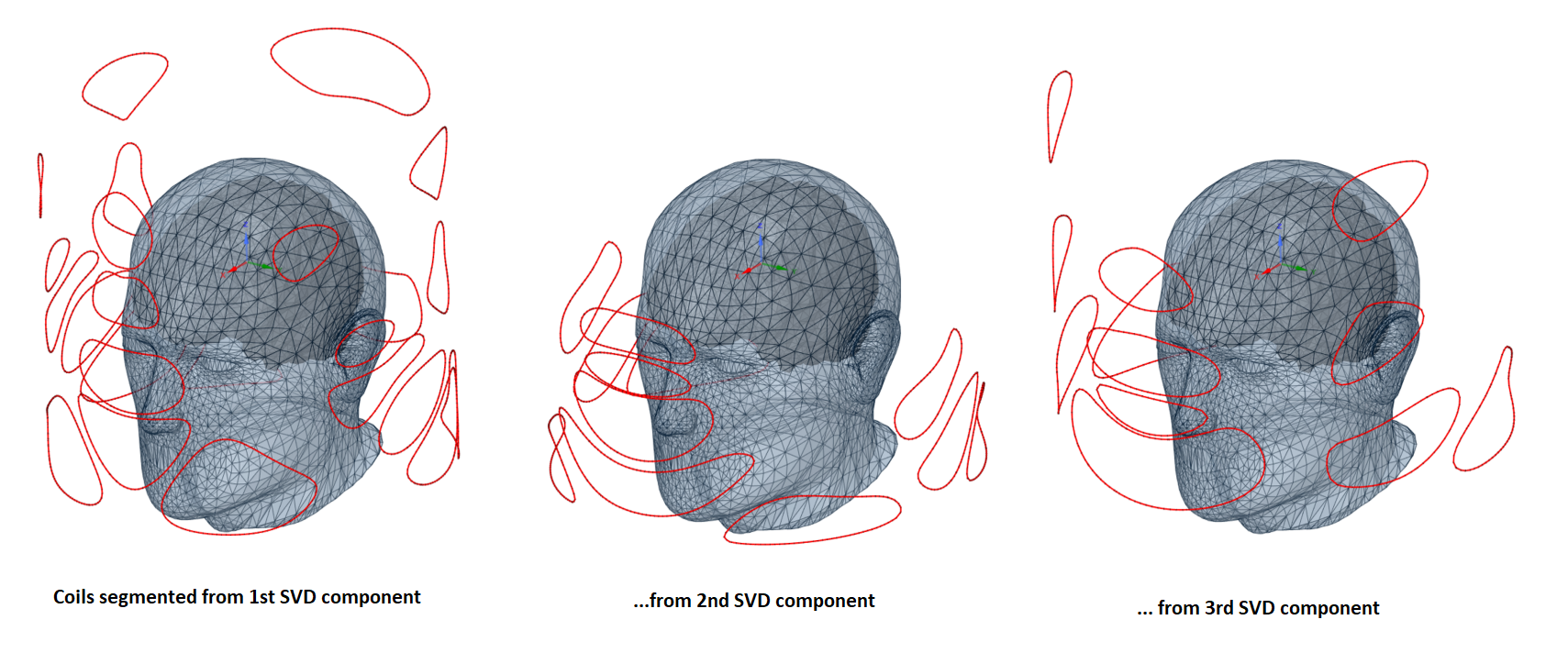
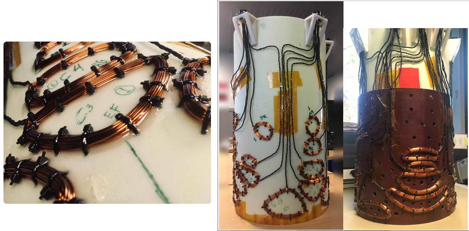
Then a Principal Component Analysis of the Ns vectorized stream functions ψs is performed to yield Ns Singular-Value-Decomposition stream functions ψSVD (Fig. 12c). The first component then captures the most variability among the subjects in the database (Fig. 14), while the last one may be specific to only one subject. Thus only the first few components are kept as potential cylindrical coils to be superimposed. However as they cannot occupy the same radius, the first SVD component is assigned to the chosen radius while higher SVD components are recalculated for outer radii, by using the Bz profile each one of them produces as a new target field. From these few ψSVD, windings are calculated from the method outlined above. In this way, we end up with a few-layer system, typically 3, corresponding to the number of novel shimming channels, shown in simulation to perform better than 16 unlimited-power SH coils [Pinho-Meneses 2020b]. Simulations performed by other groups at larger radii also point to improved performances compared to SH systems [Jia 2020]. Nevertheless, to the authors’ knowledge, no such design has yet been implemented probably due to the complexity of assembling wire loops in series with complex wire patterns (cf. Fig. 13). However there is a way out by accepting to increase the number of channels without increasing the number of layers.
SCOTCH : a Multi-Coil Array optimized for the human brain
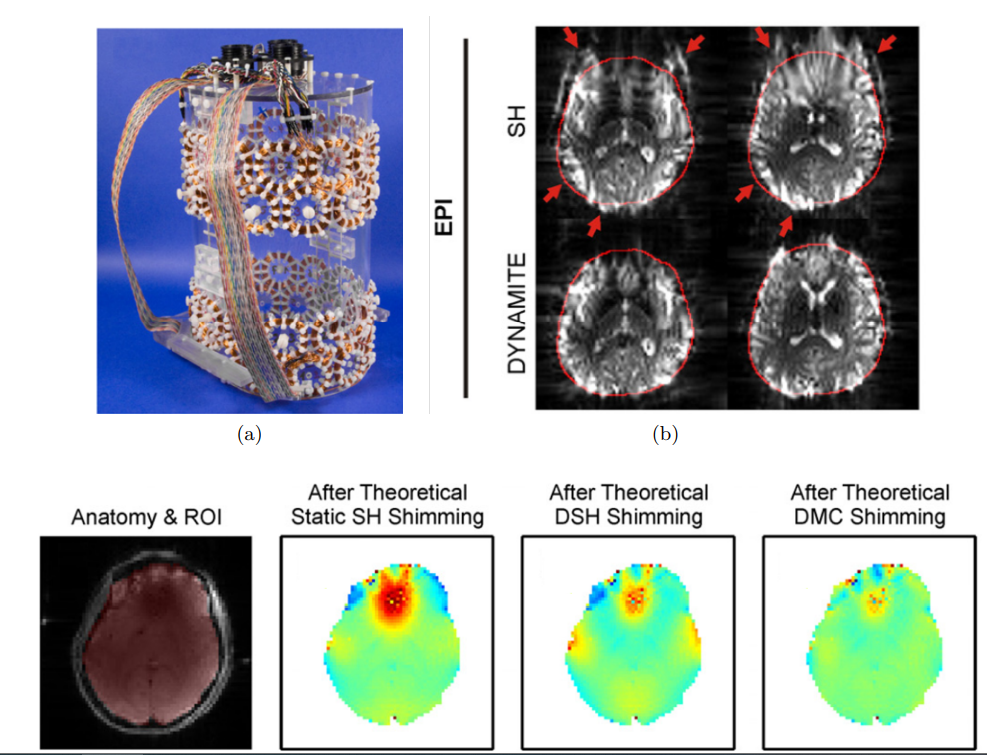
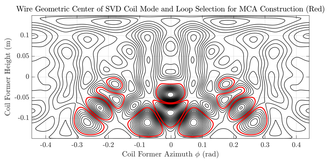
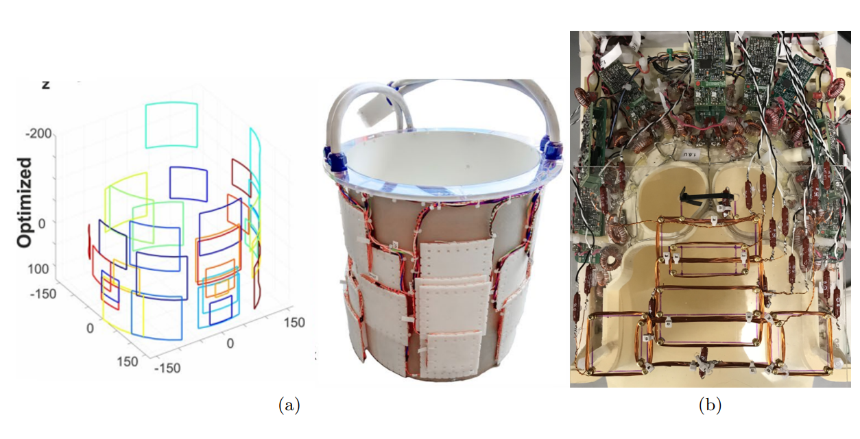
Shim multi-coil arrays (MCA) have first been introduced in 2011 as a way to improve shimming of the human brain thanks to small circular loops regularly paving a cylindrical former at the top and bottom of an RF head coil [Juchem 2011] (cf. Fig. 8). One advantage of such systems is that the small size and proximity of the loops to the subject’s head typically require less current than standard larger SH coils. Therefore they can be driven by more affordable power supplies yet compatible with multiple channels that provide the degrees of freedom to improve shimming. The smaller inductance of the loops also makes them suitable for fast switching without having to worry about eddy currents in the main magnet vessel. With up to 48 multi-turn loops, this technology proves particularly useful for dynamic shimming (or slice-by-slice shimming), whereby shim currents are updated during acquisition of 2D Echo-Planar sequences, taking advantage of ROI reduction for each selected slice [Juchem 2015]. Other teams have developed matrix-like MCAs with the same concept, regularly covering the entire cylindrical surface outside the RF coil with identical loops [Aghaeifar 2018]. Even though these systems may significantly improve shimming beyond 2nd-order SH coils, their design is actually too simplistic to truly optimize shimming for the human brain.This is why an MCA optimized for the brain was recently proposed, so-called SCOTCH, which combines the stream function SVD approach above with the multi-channel concept [Pinho-Meneses 2022]. Following the method described above, three SVD coils have first been designed as three cylindrical layers of optimal current lines. Yet to ease implementation, these current lines were gathered into bundles according to their separation around stream function extrema. This allowed a segmentation of each SVD coil into typically more than 10 bundles. For further simplification, each bundle was actually implemented as a multi-turn loop whose shape matched the outer-most current line of the bundle (such a loop approximatively yields the same Bz profile as the original bundle – cf. red lines in Fig. 14). In the end, the three-layer prototype comprised 48 loops of various size, shape, and location optimized for shimming the human brain (cf. Figs. 15-16). At 7 Tesla, with up to 3 A per channel (supplied by an open-source current driver [Arango 2016]), this was shown to be equivalent to a 96-channel matrix MCA, and to at least a full 6th-order SH system with unlimited power. It has thus reached the best performance to shim the whole human brain so far, and can be driven in dynamic mode for slice-by-slice shimming in 2D acquisitions [Pinho-Meneses 2020a]. A limitation of the cylindrical system in its current form is that it relies on a narrow 27-cm inner diameter, which implies the use of a dedicated compact RF coil isolated from the SCOTCH array with an RF shield [Luong 2022].
In the meantime, another MCA optimized for the human brain was proposed, but the shape of its 32 loops was set to squares [Aghaeifar 2020] (Fig. 17a), thereby limiting its performance compared to SCOTCH.
Other types of shim arrays
Shim arrays based on the RF coil arrays have also been proposed in recent years: they mostly share the same loops as the ones used for RF reception; the RF loops can also become DC loops via chokes that bring the shim currents while preventing RF signal leakage towards the shim amplifiers [Han 2013, Stockmann 2016, Darnell 2017]. Although nice results have been obtained with such devices, especially for dynamic shimming, their suboptimal design for B0 shimming tends to pull them out of the scope of this shim coil design session.For the sake of completeness, MCA with shimming loops orthogonal to the RF loops have also been proposed to limit the interaction with the RF loops with no need for an RF shield, while addressing the Bz component of interest more directly than when located along cylindrical formers [Zhou 2020]. A 7-channel orthogonal shim array was thus implemented above the forehead, somewhat improving shimming in the frontal lobe.
Conclusion
We have reviewed various methods to design shimming coils, starting from simple 0- and 1st-order SH coils to anatomy-driven shim multi-coil arrays. Assuming cylindrical surface geometries for the sought shimming currents, we focused our attention on a recent simple numerical method, the Dipole Boundary Method, to find out the stream function that produces whatever target B0 field pattern. Applying this to the brain anatomy, we used a principal component analysis of the stream function and translated the main components into current lines gathered around stream function extrema. From the identified bundles, we were able to segment close-to-optimal coil windings into multi-coil channels to ease implementation and add flexibility in the shimming process. As a result, we have learnt to build the best shimming coil ever designed for the brain. Of course, the same strategy can be used to design shim coil arrays dedicated to other parts of the human anatomy.Acknowledgements
Thanks to Jason Stockmann, who provided his slides from last year as well as advice to get started.
References
[Aghaeifar 2018] A. Aghaeifar, C. Mirkes, J. Bause, T. Steffen, N. Avdievitch, A. Henning and K. Scheffler. Dynamic B0 shimming of the human brain at 9.4 T with a 16- channel multi-coil shim setup. Magnetic Resonance in Medicine, vol. 80, no. 4, pages 1714–1725, October 2018.
[Aghaeifar 2020] A. Aghaeifar, J. Zhou, R. Heule, B. Tabibian, B. Schölkopf, F. Jia, M. Zaitsev, K. Scheffler. A 32‐channel multi‐coil setup optimized for human brain shimming at 9.4T, Magn Reson Med.;83:749–764, 2020.
[Amrein 2022]: P. Amrein, F. Jia, M. Zaitsev, S. Littin. CoilGen: Open-source MR coil layout generator. Magn Reson Med, 88,3:1465-1479, sept. 2022.
[Arango 2016] N. Arango, J. P. Stockmann, T. Witzel, L. L. Wald and J. White. Opensource, low-cost, flexible, current feedback-controlled driver circuit for local B0 shim coils and other applications. Proc. Int. Soc. Magn. Reson. Med, 2016.
[Arango 2020] N. Arango, J. Stockmann, E. Adalsteinsson and J. White. Computational Shim Coil Design Applied to Augmenting a Shim Array with a Non-Eye-Occluding Face Plate. In Proceedings of the 4:th Annual Meeting of the International Society for Magnetic Resonance in Medicine, volume 28, page 4224, Virtual ISMRM 2020.
[Brideson 2002]: M. A. Brideson, L. K. Forbes and S. Crozier. Determining complicated winding patterns for shim coils using stream functions and the target-field method. Concepts in Magnetic Resonance, vol. 14, no. 1, pages 9–18, 2002.
[Chang2018] P. Chang, S. Nassirpour and A. Henning. Modeling real shim fields for very high degree (and order) B0 shimming of the human brain at 9.4 T. Magnetic Resonance in Medicine, vol. 79, no. 1, pages 529–540, 2018.
[Damme 2021] L. V. Damme, F. Mauconduit, T. Chambrion, N. Boulant and V. Gras. Universal nonselective excitation and refocusing pulses with improved robustness to off-resonance for Magnetic Resonance Imaging at 7 Tesla with parallel transmission. Magnetic Resonance in Medicine, vol. 85, no. 2, pages 678-693, 2021.
[Darnell 2017] D. Darnell, T.-K. Truong and A. W. Song. Integrated parallel reception, excitation, and shimming (iPRES) with multiple shim loops per radio-frequency coil element for improved B0 shimming. Magnetic Resonance in Medicine, vol. 77, no. 5, pages 2077–2086, 2017.
[Forbes 2001]: L. K. Forbes and S. Crozier. A novel target-field method for finite-length magnetic resonance shim coils: I. Zonal shims. Journal of Physics D: Applied Physics, vol. 34, no. 24, pages 3447–3455, December 2001.
[Forbes 2002]: L. K. Forbes and S. Crozier. A novel target-field method for finite-length magnetic resonance shim coils: II. Tesseral shims. Journal of Physics D: Applied Physics, vol. 35, no. 9, pages 839–849, May 2002.
[Forbes 2003]: L. K. Forbes and S. Crozier. A novel target-field method for magnetic resonance shim coils: III. Shielded zonal and tesseral coils. Journal of Physics D: Applied Physics, vol. 36, no. 2, pages 68–80, January 2003.
[Han 2013] H. Han, A. W. Song and T.-K. Truong. Integrated parallel reception, excitation, and shimming (iPRES): Integrated Parallel Reception, Excitation, and Shimming. Magnetic Resonance in Medicine, vol. 70, no. 1, pages 241–247.
[Hetherington 2021]: H. P. Hetherington, C. H. Moon, M. Schwerter, N. J. Shah and J. W. Pan. Dynamic B 0 shimming for multiband imaging using high order spherical harmonic shims. Magnetic Resonance in Medicine, vol. 85, no. 1, pages 531–543, January 2021.
[Jia 2020]: F. Jia, H. Elshatlawy, A. Aghaeifar, Y. Chu, Y. Hsu, S. Littin, S. Kroboth, H. Yu, P. Amrein, X. Gao, W. Yang, P. LeVan, K. Scheffler and M. Zaitsev. Design of a shim coil array matched to the human brain anatomy. Magnetic Resonance in Medicine, vol. 83, no. 4, pages 1442–1457, April 2020.
[Juchem 2010] C. Juchem, T. W. Nixon, S. McIntyre, D. L. Rothman and R. A. d. Graaf. Magnetic field homogenization of the human prefrontal cortex with a set of localized electrical coils. Magnetic Resonance in Medicine, vol. 63, no. 1, pages 171–180, 2010.
[Juchem 2011] C. Juchem, T. W. Nixon, S. McIntyre, V. O. Boer, D. L. Rothman and R. A. d. Graaf. Dynamic multi-coil shimming of the human brain at 7T. Journal of Magnetic Resonance, vol. 212, no. 2, pages 280 – 288, 2011.
[Juchem 2015] C. Juchem, S. Umesh Rudrapatna, T. W. Nixon and R. A. de Graaf. Dynamic multi-coil technique (DYNAMITE) shimming for echo-planar imaging of the human brain at 7 Tesla. NeuroImage, vol. 105, pages 462–472, January 2015.
[Lemdiasov 2005]: R. A. Lemdiasov and R. Ludwig. A stream function method for gradient coil design. Concepts in Magnetic Resonance Part B: Magnetic Resonance Engineering, vol. 26B, no. 1, pages 67–80, 2005.
[Lopez 2009a]: H. S. Lopez, F. Liu, M. Poole and S. Crozier. Equivalent Magnetization Current Method Applied to the Design of Gradient Coils for Magnetic Resonance Imaging. IEEE Transactions on Magnetics, vol. 45, no. 2, pages 767–775, February 2009.
[Lopez 2009b]: H. S. Lopez, M. Poole and S. Crozier. An improved equivalent magnetization current method applied to the design of local breast gradient coils. Journal of Magnetic Resonance, vol. 199, no. 1, pages 48–55, July 2009.
[Luong 2022]: Michel Luong, Guillaume Ferrand , Edouard Chazel , Paul-François Gapais , Vincent Gras , Nicolas Boulant , and Alexis Amadon, A Compact 16Tx-32Rx Geometrically Decoupled Phased Array for 11.7T MRI, #707, ISMRM2022, London, UK.
[Peeren 2003]: G. N. Peeren. Stream function approach for determining optimal surface currents. PhD Thesis, Technische Universiteit Eindhoven, 2003.
[Pinho Meneses 2020] Bruno Pinho Meneses and Alexis Amadon. Static-magnetic-field shimming coil system for magnetic resonance imaging, patent no. WO2020/212463A1, October 2020.
[Pinho Meneses 2020a] B. Pinho Meneses and A. Amadon. Human brain shimming performance comparison between matrix-like and stream-function SVD-based multicoil arrays. In Proceedings of the 28th Annual Meeting of ISMRM, volume 28, page 4222, Virtual Conference, 2020.
[Pinho Meneses 2020b] B. Pinho Meneses and A. Amadon. A fieldmap-driven few-channel shim coil design for MRI of the human brain. Physics in Medicine & Biology, vol. 66, no. 1, 2020.
[Pinho-Meneses 2021]: Static Field Shimming in the Human Brain for Ultra-High Field MRI: Conceptual Limits and Development of a Novel Hardware Prototype. PhD thesis, Université Paris-Saclay, 2021.
[Pinho-Meneses 2022]: Bruno Pinho Meneses , Jason P. Stockmann , Nicolas Arango , Paul-François Gapais, Eric Giacomini, Franck Mauconduit, Vincent Gras, Nicolas Boulant, Alexandre Vignaud, Michel Luong, Alexis Amadon, Shim coils tailored for correcting B0 inhomogeneity in the human brain (SCOTCH): Design methodology and 48-channel prototype assessment in 7-Tesla MRI, NeuroImage Volume 261, November 2022, 119498.
[Pissanetzky 1992]: ] S. Pissanetzky. Minimum energy MRI gradient coils of general geometry. Measurement Science and Technology, vol. 3, no. 7, pages 667–673, July 1992.
[Poole 2007]: M. Poole. Improved Equipment and Techniques for Dynamic Shimming in High Field MRI. PhD, University of Nottingham, 2007.
[Poole 2010]: M. Poole, P. Weiss, H. S. Lopez, M. Ng and S. Crozier. Minimax current density coil design. Journal of Physics D: Applied Physics, vol. 43, no. 9, page 095001, March 2010.
[Poole 2014]: M. S. Poole and N. Jon Shah. Convex optimisation of gradient and shim coil winding patterns. Journal of Magnetic Resonance, vol. 244, pages 36–45, July 2014.
[Romeo 1984]: F. Roméo and D. I. Hoult. Magnet field profiling: Analysis and correcting coil design. Magnetic Resonance in Medicine, vol. 1, no. 1, pages 44–65, 1984.
[Stockmann 2016] J. P. Stockmann, T. Witzel, B. Keil, J. R. Polimeni, A. Mareyam, C. LaPierre, K. Setsompop and L. L. Wald. A 32-channel combined RF and B0 shim array for 3T brain imaging. Magnetic resonance in medicine, vol. 75, no. 1, pages 441–451, January 2016.
[Turner 1986]: R. Turner. A target field approach to optimal coil design. Journal of Physics D: Applied Physics, vol. 19, no. 8, pages L147–L151, August 1986.
[Zhou 2020] J. Zhou, J. P. Stockmann, N. Arango, T. Witzel, K. Scheffler, L. L. Wald and F. Lin. An orthogonal shim coil for 3T brain imaging. Magnetic Resonance in Medicine, vol. 83, no. 4, pages 1499–1511, April 2020.
Figures