4961
A numerical investigation of meander and solenoidal dipole antenna array configurations for 7T MR applications.1Biomedical Engineering, The State University of New York at Buffalo, Buffalo, NY, United States
Synopsis
Keywords: RF Arrays & Systems, RF Arrays & Systems
Motivation: Optimize dipole antennas for 7T MR applications.
Goal(s): Enable compact 300MHz dipole structures for higher-channel arrays.
Approach: Introduce a solenoidal dipole design and evaluate against meander designs using numerical simulations.
Results: Analyze H-field efficiency, electric-field distributions, coupling, and Q-factors in multi-channel arrays.
Impact: The introduction of a solenoidal dipole design overcomes limitations posed by meander structures, enabling shorter and compact 300MHz dipole antennas for 7T MR applications within higher-channel multi-channel arrays, positively impacting MR imaging efficiency and signal quality.
Introduction
The exclusive reliance on physical dimensions to control the tuning frequency of conventional dipole antennas poses challenges at ultra-high field strengths, leading to impractically long lengths and inefficient MR imaging due to field wastage in smaller samples1-11. To address this, meander dipoles1,3 bend conductors in a compact meandering pattern, effectively minimizing total length and enabling adaptable construction based on sample size. However, the bulkiness of meander patterns poses integration challenges in multi-channel arrays with higher channel counts, crucial for enhanced SNR and faster scans in ultra-high field MR imaging. To tackle this limitation, we devised a dipole design featuring solenoidal-shaped arms with an optimal number of turns and gaps. This solenoidal approach enables the creation of a considerably shorter and more compact 300MHz dipole structure, facilitating integration into array topologies with larger channel counts. In our study, we conducted numerical simulations comparing the proposed solenoidal dipole design with the meander dipole antenna in various array configurations, focusing on inter-element coupling, Q-factor evaluations, H-field efficiency, and normalized SNR90 distribution assessments.Method
For both dipole topologies, three multi-channel array configurations with 4, 8, and 16 channel counts were numerically simulated. Figures 1A and 1B show the dimensions of the meander dipole arm and solenoidal dipole arm.Meander dipole dimensions:
• Total length: 252mm
• Meander structure length: 76mm
• Meander structure width: 30.92mm
• Conductor width: 4mm
• Meander bends gap: 2mm
Solenoidal dipole dimensions:
• Total length: 259mm
• Total structure width: 4.70mm
• Conductor width: 1mm
• Number of turns: 25 on each arm
• Gap between turns: 4.10mm
To match the impedance at 50, each design used a parallel capacitor to the excitation port, while tuning was entirely dependent on the dimensions of the dipole designs. Furthermore, 4,8, and 16-channel combinations for both systems were designed, and electromagnetic simulations using CST Studio Suite were conducted. Figure 1C depicts the simulation configuration used for the array simulations. A cylindrical phantom (radius:115mm, length:255mm) with human brain tissue parameters was incorporated in the simulation: Ɛr:50, σ:0.6 S/m.
Both designs’ array configurations were evaluated using inter-element coupling, Q-factor, H-field efficiency, and normalized SNR90 maps. Q-factor was calculated using (Center frequency/3dB Bandwidth) formula and normalized SNR90 maps were calculated using (f2*B1-)/(√Pabs) equation, where f is the resonant frequency, B1- is the receive-B1 field, and Pabs is the estimated absorbed power over the imaging sample volume.
Results
Figures 2A and 2B display matching and inter-element decoupling S-parameters for meander and solenoidal dipoles in various array designs. Both dipoles performed similarly in 4, 8, and 16-channel arrays for inter-element decoupling. Notably, the solenoidal dipole exhibited a 105% higher Q-factor than the meander dipole (6.08 vs. 2.95). H-field efficiency, normalized to input power, is shown in Figures 3A and 3B for the central axial and sagittal slices of the cylindrical phantom. The comparison revealed that the solenoidal dipole generated slightly more efficient H-fields, with a 2.19% improvement over most central slices in all array configurations. Figure 3C illustrates electric field distributions in the central axial slices of the cylindrical phantom for all array configurations. The solenoidal dipole reduced peak electric field values by an average of 3.69%. In Figures 4A and 4B, the 1D profiles of normalized H-fields in the central axial and sagittal lines for meander and solenoidal dipole configurations are shown. These profiles indicate similar field values at the phantom center but slightly improved field distribution values at the peripheral regions of the cylindrical phantom for the solenoidal dipole. Figures 5A and 5B depict SNR maps (dB) in the central axial region of the phantom for meander and solenoidal dipole array configurations. Figure 5C shows 1D profiles of SNR maps in arbitrary units (A.U.). The comparison shows that the solenoidal dipole generated SNR values similar to the meander dipole but provided better coverage in the peripheral region of the phantom volume.Conclusion
This study addresses challenges with meander dipoles at 7T/300MHz MR applications and introduces a solenoidal-shaped dipole design, enabling compact dipole structures for inclusion in high-channel-count arrays. Based on the conducted numerical investigation for 4,8, and 16-channel configurations, the proposed design outperformed meander design, offering a 105% higher Q-factor, comparable H-fields, reduced electric field peaks and improved SNR coverage in multi-channel arrays.Acknowledgements
No acknowledgement found.References
1. A.J. Raaijmakers, O. Ipek, D.W. Klomp, C. Possanzini, P.R. Harvey, J.J. Lagendijk, C.A. van den Berg, Magn. Reson. Med. 66, 1488–1497 (2011)
2. Raaijmakers AJ, Luijten PR, van den Berg CA. Dipole antennas for ultrahigh-field body imaging: a comparison with loop coils. NMR Biomed. 2016 Sep;29(9):1122-30. doi: 10.1002/nbm.3356. Epub 2015 Aug 17. PMID: 26278544
3. Raaijmakers AJ, Italiaander M, Voogt IJ, Luijten PR, Hoogduin JM, Klomp DW, van den Berg CA. The fractionated dipole antenna: A new antenna for body imaging at 7 Tesla. Magn Reson Med. 2016 Mar;75(3):1366-74. doi: 10.1002/mrm.25596. Epub 2015 May 2. PMID: 25939890.
4. Rupprecht S, Sica CT, Chen W, Lanagan MT, Yang QX. Improvements of transmit efficiency and receive sensitivity with ultrahigh dielectric constant (uHDC) ceramics at 1.5 T and 3 T. Magn Reson Med. 2018;79(5):2842-2851. doi:10.1002/mrm.26943
5. Wang C, Zhang X. Evaluation of B1+ and E field of RF Resonator with High Dielectric Insert. ISMRM p3054 (2009)
6. Bhosale AA, Gawande D, Zhang X. B1 field flattening and length control of half-wave dipole antenna with discrete dielectric coating. Proceedings of the International Society for Magnetic Resonance in Medicine ... Scientific Meeting and Exhibition. International Society for Magnetic Resonance in Medicine. Scientific Meeting and Exhibition. 2022 May;30:4104. PMID: 36071703; PMCID: PMC9445060.
7. Bhosale AA, Gawande D, Zhang X. A Dielectric Material Coated Half-Wave Dipole antenna for Ultrahigh Field MRI at 7T/300MHz. Proc Int Soc Magn Reson Med Sci Meet Exhib Int Soc Magn Reson Med Sci Meet Exhib. 2022 May;30:4103. PMID: 36071701; PMCID: PMC9445058.
8. Bhosale, A., L. Ying, and X. Zhang. A 15-channel End-coated Half-wave Dipole Antenna Array System for Foot/Ankle/Calf Imaging at 7T. in Proceedings of the Annual Meeting of ISMRM 2022. 2022. London, UK.
9. Bhosale AA, Ying LL, Zhang X. An 8-Channel High-permittivity Dielectric Material-Coated Half-Wave Dipole Antenna Array for Knee Imaging at 7T. Proc Int Soc Magn Reson Med Sci Meet Exhib Int Soc Magn Reson Med Sci Meet Exhib. 2022 May;30:4105. PMID: 36071705; PMCID: PMC9445071.
10. Bhosale, A. A., Ying, L., & Zhang, X. (2023). A Systematic Comparison of Different Dipole Antenna Array Configurations for Knee Imaging Applications at 7T. Proceedings of the International Society for Magnetic Resonance in Medicine ... Scientific Meeting and Exhibition. International Society for Magnetic Resonance in Medicine. Scientific Meeting and Exhibition, 31, 4257.
11. Bhosale, A. A., & Zhang, X. (2023). Performance and B1 Efficiency Analysis of Different Dipole Antenna Types at 7T. Proceedings of the International Society for Magnetic Resonance in Medicine ... Scientific Meeting and Exhibition. International Society for Magnetic Resonance in Medicine. Scientific Meeting and Exhibition, 31, 4255.
Figures
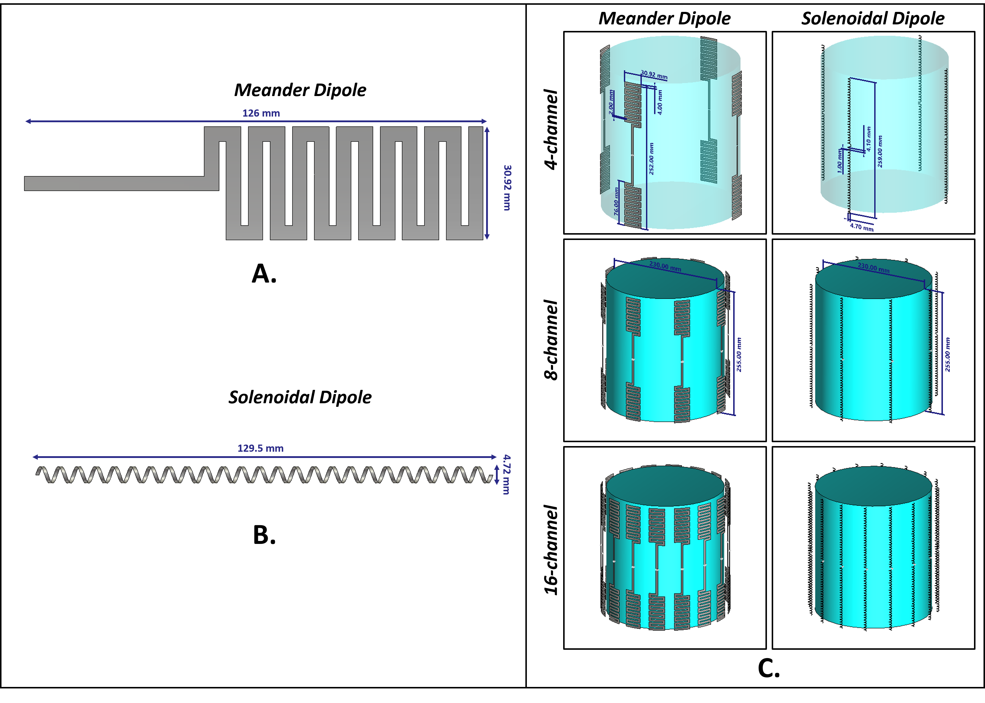
Figure1. Dipole Design Comparison and Multi-Channel Array Configuration Simulation Setup. (A) Meander dipole conductor arm, (B) Solenoidal dipole conductor arm, and (C) Simulation configuration for 4, 8, and 16-channel array setups, along with a cylindrical phantom and labeled dimensions.
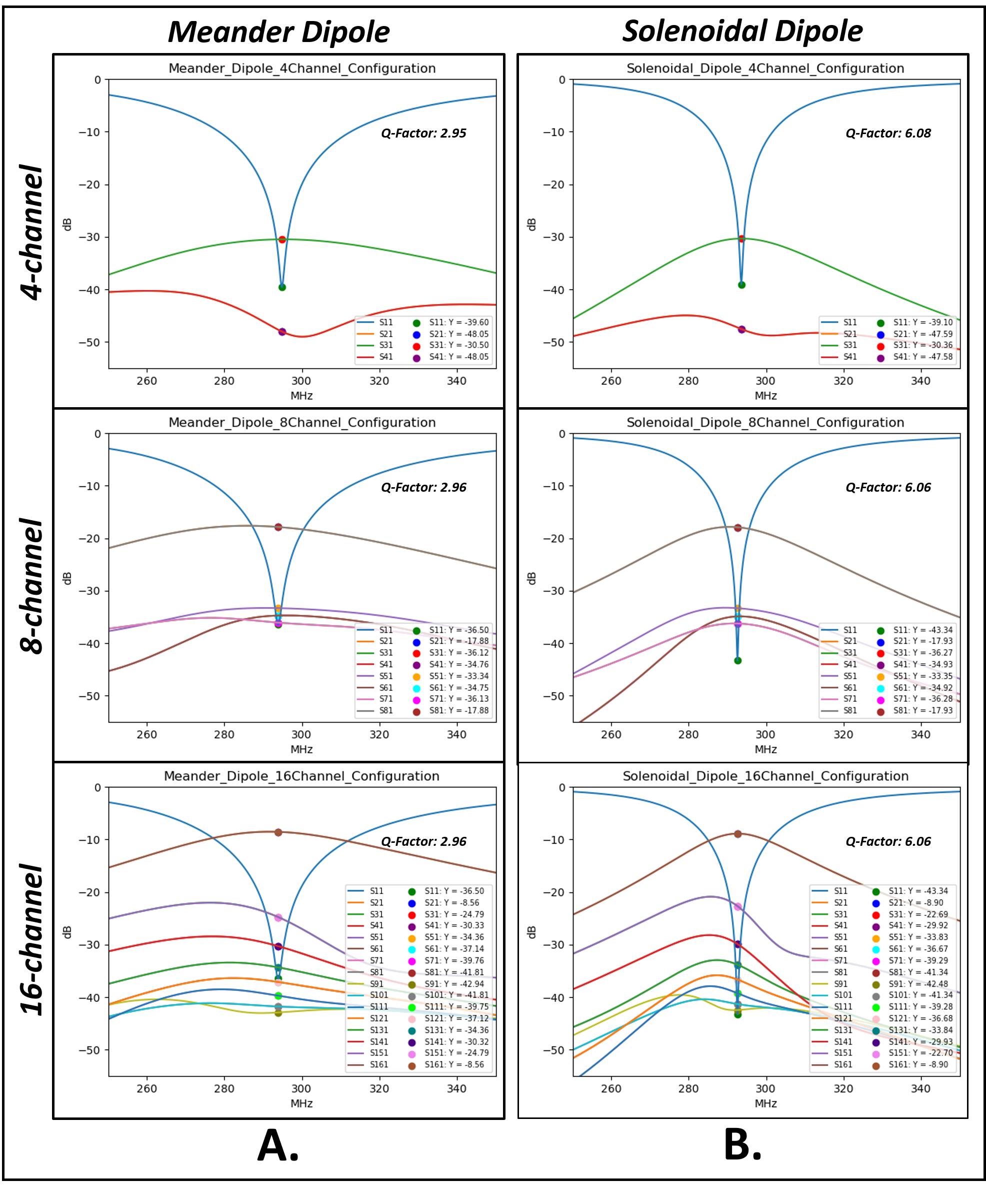
Figure2. S-Parameter Comparison of Meander and Solenoidal Dipole Array Configurations. (A) Meander dipole array S-parameters, featuring matching at the tuned frequency, transmission coefficient values for inter-element coupling, and labeled Q-factor. (B) Solenoidal dipole array S-parameters, providing a basis for comparative analysis.
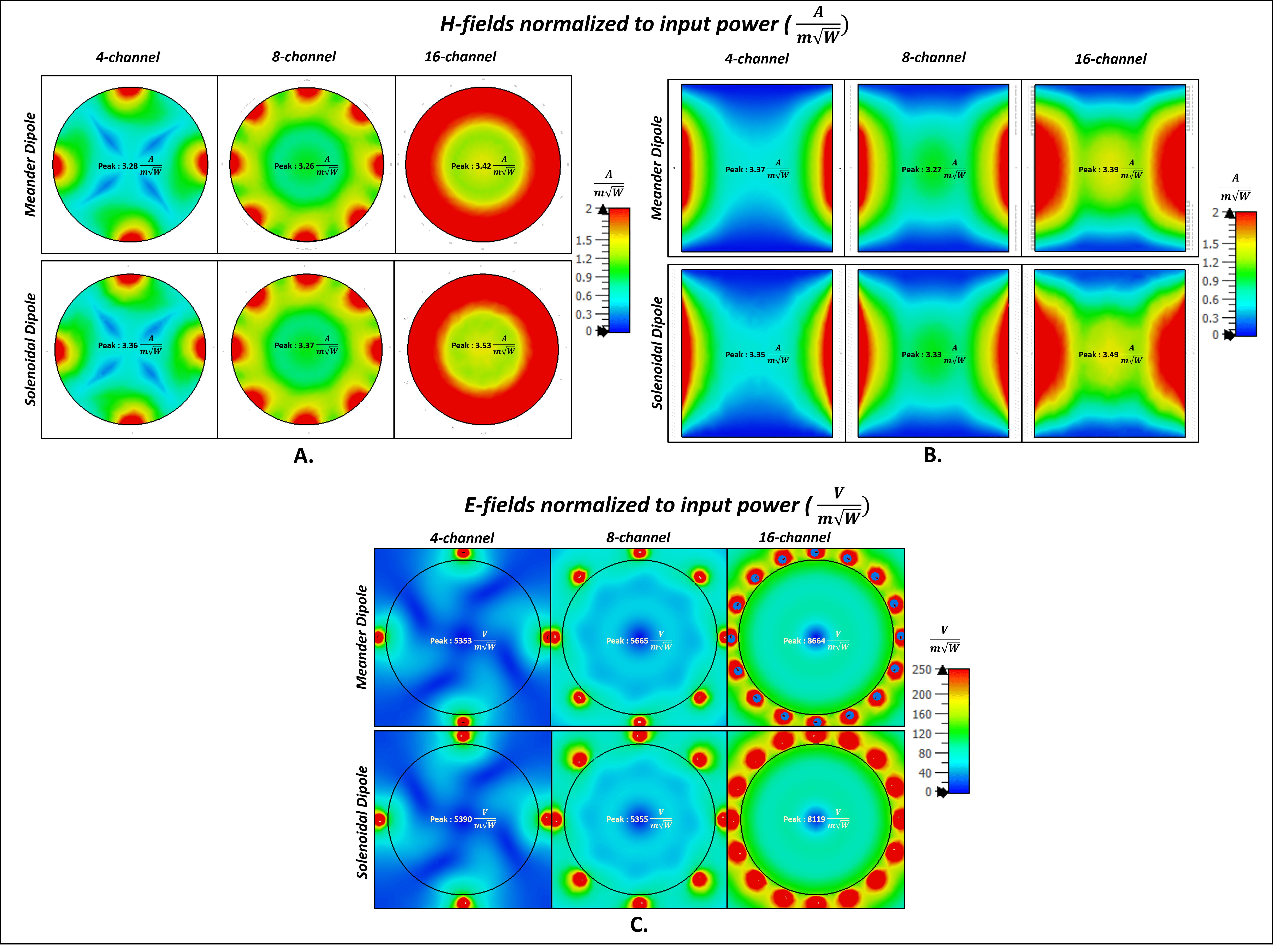
Figure3. Field Distribution Maps in Different Slice Views. (A) Normalized H-field distribution maps in central axial slice for solenoidal and meander dipole array configurations with peak H-field values labeled. (B) Normalized H-field distribution maps in central sagittal slice with peak H-field values labeled. (C) Normalized E-field distribution in central axial slice with peak electric field values labeled.
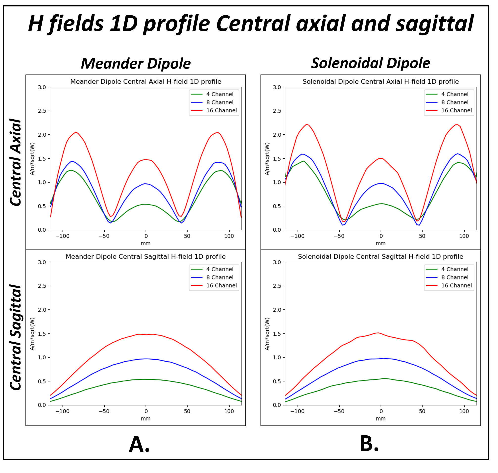
Figure4. 1D Profiles of H-Field Distribution in different Array Configurations. (A) 1D profiles of normalized H-fields in the central axial and central sagittal lines for meander dipole arrays. (B) 1D profiles of normalized H-fields in the central axial and central sagittal lines for solenoidal dipole arrays. Solenoidal dipole arrays exhibit enhanced H-field coverage in the phantom's peripheral region while maintaining comparable central region coverage.
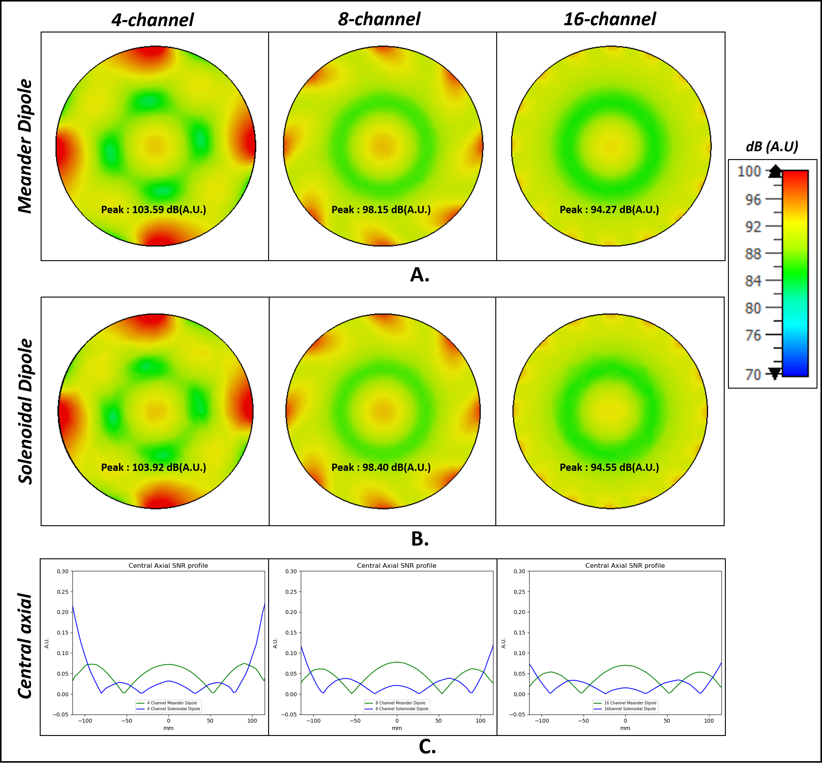
Figure5. SNR Mapping and Comparative Analysis. (A) Central axial SNR maps for meander dipole array configurations, with peak SNR values (dB A.U.) labeled in each plot. (B) Central axial SNR maps for solenoidal dipole array configurations, featuring labeled peak SNR values in (dB A.U.). (C) 1D profiles of SNR maps in the central axial lines for meander dipole array configurations compared with solenoidal dipole array configurations.