4960
Joint pre-emphasis and post-processing method for improving GIRF-based spiral trajectory correction1Center for Biomedical Imaging Research, Department of Biomedical Engineering, School of Medicine, Tsinghua University, Beijing, China
Synopsis
Keywords: System Imperfections, System Imperfections: Measurement & Correction, Trajectory correction
Motivation: Gradient imperfections typically cause ringing and blurring artifacts in spiral imaging. Gradient impulse response function (GIRF) characterizes the gradient system and can be applied for gradient prediction in image reconstruction. However, the low-pass characteristic of the gradient system could cause a penalty of the achieved resolution.
Goal(s): This work aims to improve the GIRF-based spiral trajectory correction.
Approach: A joint pre-emphasis and post-processing method was introduced to correct spiral trajectory. The effectiveness of our proposed method was tested on the phantom and in-vivo experiments.
Results: The ringing and blurring artifacts were further mitigated using our proposed method.
Impact: A joint pre-emphasis and post-processing correction strategy was proposed in this study. The results of phantom and in-vivo experiments indicate that our proposed method yields good image quality and effectively reduces the loss of the actual resolution.
Introduction
In spiral imaging, gradient imperfections typically result in ringing artifacts and image blurring. Gradient impulse response function (GIRF) 1-7 enables the correction of the spiral gradient waveform by predicting the actual gradient output through convolution of the nominal gradient waveform (input) with GIRF. The gradient system-related image artifacts can be significantly reduced in the images reconstructed using the GIRF-based predictions. However, the actual acquired resolution is compromised due to the low-pass characteristic of the gradient system 2. Thus, in this study, a joint pre-emphasis and post-processing method is proposed to further enhance GIRF-based correction. The overall image quality and the achieved resolution are improved.Theory
Under the assumption that the gradient system is linear and time-invariant (LTI), GIRF-based correction can be performed to improve image quality. The schematic diagram of our proposed method is shown in Figure 1.1. GIRF-based post-processing correction
For conventional GIRF-based correction, GIRF is used to predict the actual outputs of a gradient system:
$$g_{out}(t)=g_{in}(t)*h(t)$$
The low-pass characteristic of the gradient system reduces the actual resolution. However, the conventional GIRF-based correction cannot compensate for this problem.
2. Pre-emphasis
Pre-emphasis is basically a high-pass filter designed to counteract the system-induced waveform distortion by modifying the gradient input. The pre-emphasized gradient $$$g_{pre}(t)$$$ was played out during spiral imaging, then the actual gradient outputs would be closer to the nominal waveform, i.e., $$$g_{out}(t)\approx g_{in}(t)$$$. However, the eddy-current compensation may be insufficient because the pre-emphasis filter was determined by a limited number of exponential terms and the bandwidth of gradient amplifiers is limited.
3. Joint pre-emphasis and post-processing correction
In this work, to overcome the drawbacks of the above two methods, a joint pre-emphasis and post-processing method was proposed. Both the behavior of eddy-current compensation and the characteristics of the gradient system can be described by combined GIRF $$$h_{com}(t)$$$. This is subsequently employed to correct the spiral trajectory, i.e., $$$g_{out}(t)=g_{in}(t)*h_{com}(t)$$$.
Materials and Methods
All experiments were performed on an Ingenia CX 3.0T scanner (Philips) using a 32-channel head coil.1. GIRF Measurements
The GIRF measurements were performed with a spherical phantom using our previously proposed interleaved off-isocenter method 8. Traditional GIRF $$$h(t)$$$ is determined by measured waveforms and inputs. Subsequently, to measure the combined GIRF $$$h_{com}(t)$$$, input gradients were pre-emphasized and then played out.
2. Data acquisition
Both phantom and in-vivo experiments were performed to validate the effectiveness of the proposed correction method. The spiral waveforms with and without pre-emphasis were used respectively to acquire data in the following experiments.
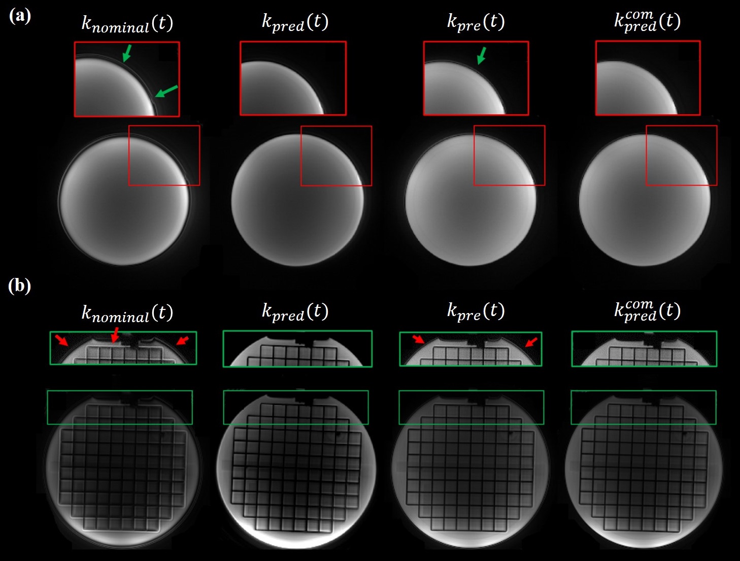
Experiment 1: FOV = 210×210 mm2, resolution = 1.0×1.0×4.0 mm3, TE/TR = 50/3000 ms. A 20-shot uniform-density spiral (UDS) acquisition with a readout window of 8.0 ms was used to obtain axial images of a spherical phantom and ACR phantom.
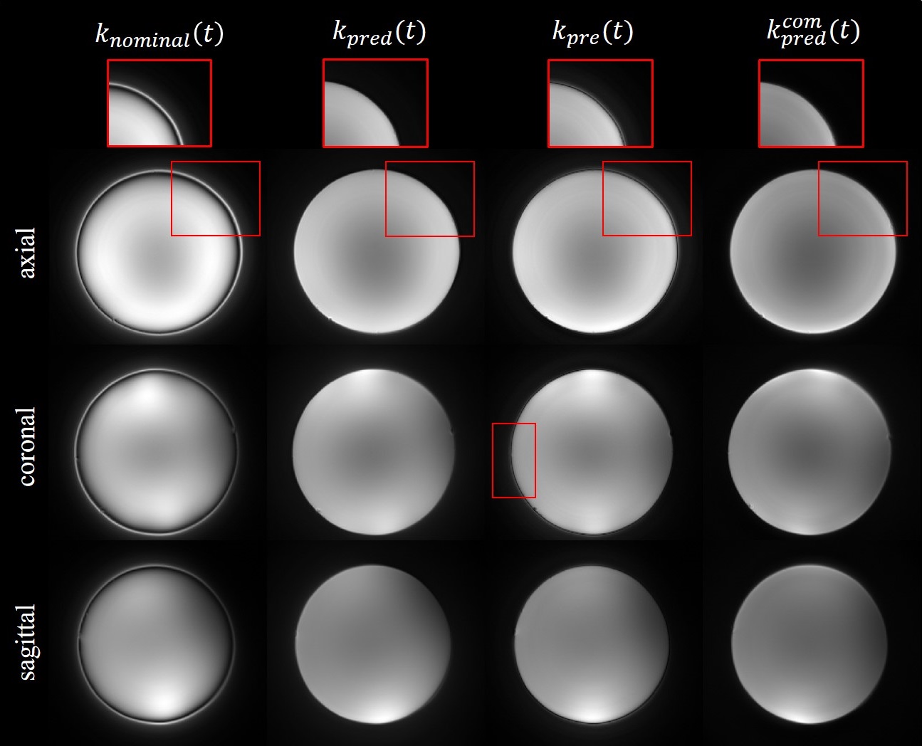
Experiment 2: FOV = 210×210 mm2, resolution = 1.0×1.0×4.0 mm3, TE/TR = 50/3000 ms. The axial, coronal and sagittal slices of a phantom were acquired using a 24-shot variable-density spiral (VDS) acquisition with a readout window of 15.7 ms.
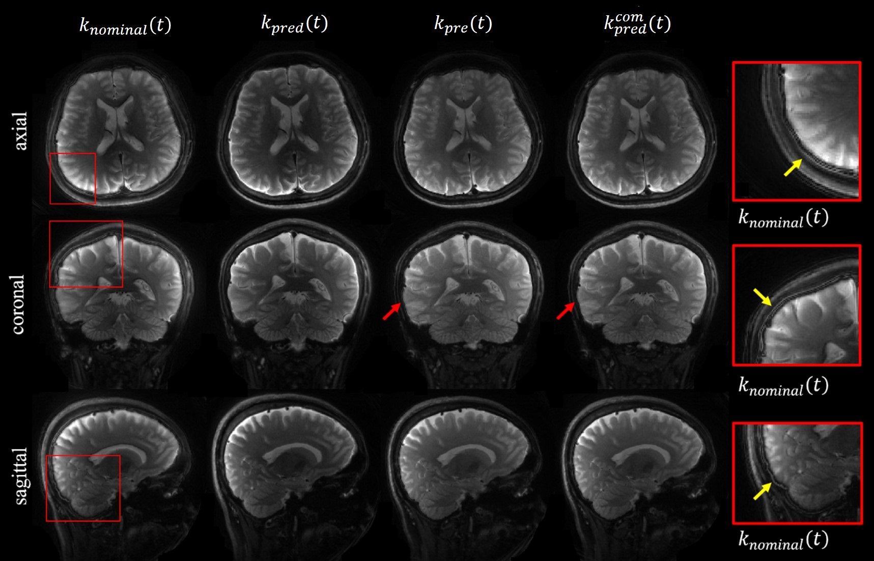
Experiment 3: FOV = 210×210 mm2, resolution = 1.0×1.0×4.0 mm3, TE/TR = 50/3000 ms. The axial, coronal and sagittal slices covering the brain of a subject were acquired using a 20-shot UDS acquisition with a readout window of 8.0 ms.
3. Image reconstruction
For comparison purposes, the spiral images were reconstructed using the following four different trajectories. (i) nominal trajectories $$$k_{nominal}(t)$$$, (ii) predicted trajectories $$$k_{pred}(t)$$$ obtained by the conventional GIRF, (iii) pre-emphasized trajectories $$$k_{pre}(t)$$$ and (iv) predicted trajectories $$$k_{pred}^{com}(t)$$$ obtained by our proposed combined GIRF.
Results and Discussion
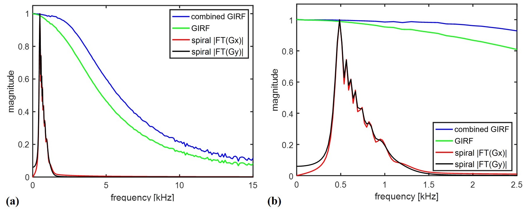
The magnitude of measured conventional GIRF $$$H(\omega)$$$, measured combined GIRF $$$H_{com}(\omega)$$$, and the spectrum of nominal spiral gradients $$$G_x$$$ and $$$G_y$$$ are shown in Figure 2. The bandwidth of $$$H_{com}(\omega)$$$ is wider. Pre-emphasis is favorable for fast acquisitions with rapid gradient switching.The spherical phantom and ACR phantom images acquired using UDS are shown in Figure 3. Figure 4 shows the axial, coronal and sagittal phantom images acquired using VDS. The in-vivo results reconstructed using four different trajectories are shown in Figure 5. GIRF-based correction and pre-emphasis can yield good image quality. Residual ringing and blurring artifacts are removed and more details are retained in the reconstructions using our proposed method. Furthermore, the maximum value of $$$k_{pred}(t)$$$ is lower than that of $$$k_{pred}^{com}(t)$$$. The results reconstructed by $$$k_{pred}^{com}(t)$$$ show better image quality with effectively reduced loss of actual resolution.
Conclusion
In this study, a joint pre-emphasis and post-processing method was proposed to further enhance the performance of GIRF-based trajectory correction. The spiral images reconstructed using our proposed method show superior image quality with effectively minimized loss of actual resolution.Acknowledgements
No acknowledgment found.References
1. Vannesjo SJ, Haeberlin M, Kasper L, et al. Gradient system characterization by impulse response measurements with a dynamic field camera. Magn Reson Med 2013; 69: 583–593
2. Vannesjo S J, Graedel N N, Kasper L, et al. Image reconstruction using a gradient impulse response model for trajectory prediction [J]. Magn Reson Med, 2016, 76(1): 45-58
3. Campbell-Washburn A E, Xue H, Lederman R J, et al. Real-time distortion correction of spiral and echo planar images using the gradient system impulse response function [J]. Magn Reson Med, 2016, 75(6): 2278-2285
4. Rahmer J, Schmale I, Mazurkewitz P, et al. Non-Cartesian k-space trajectory calculation based on concurrent reading of the gradient amplifiers' output currents [J]. Magn Reson Med, 2021, 85(6): 3060-3070.
5. Stich M, Wech T, Slawig A, et al. Gradient waveform pre-emphasis based on the gradient system transfer function [J]. Magn Reson Med, 2018, 80(4): 1521-1532.
6. Robison R K, Devaraj A, Pipe J G. Fast, simple gradient delay estimation for spiral MRI [J]. Magn Reson Med, 2010, 63(6): 1683-1690
7. Addy N O, Wu H H, Nishimura D G. Simple method for MR gradient system characterization and k‐space trajectory estimation [J]. Magnetic resonance in medicine, 2012, 68(1): 120-129.
8. Li G, Chen S, and Guo H. Accelerate GIRF measurement using an interleaved off-isocenter method. In Proceedings of the 27th Annual Meeting of ISMRM. 2019; 1774.
Figures
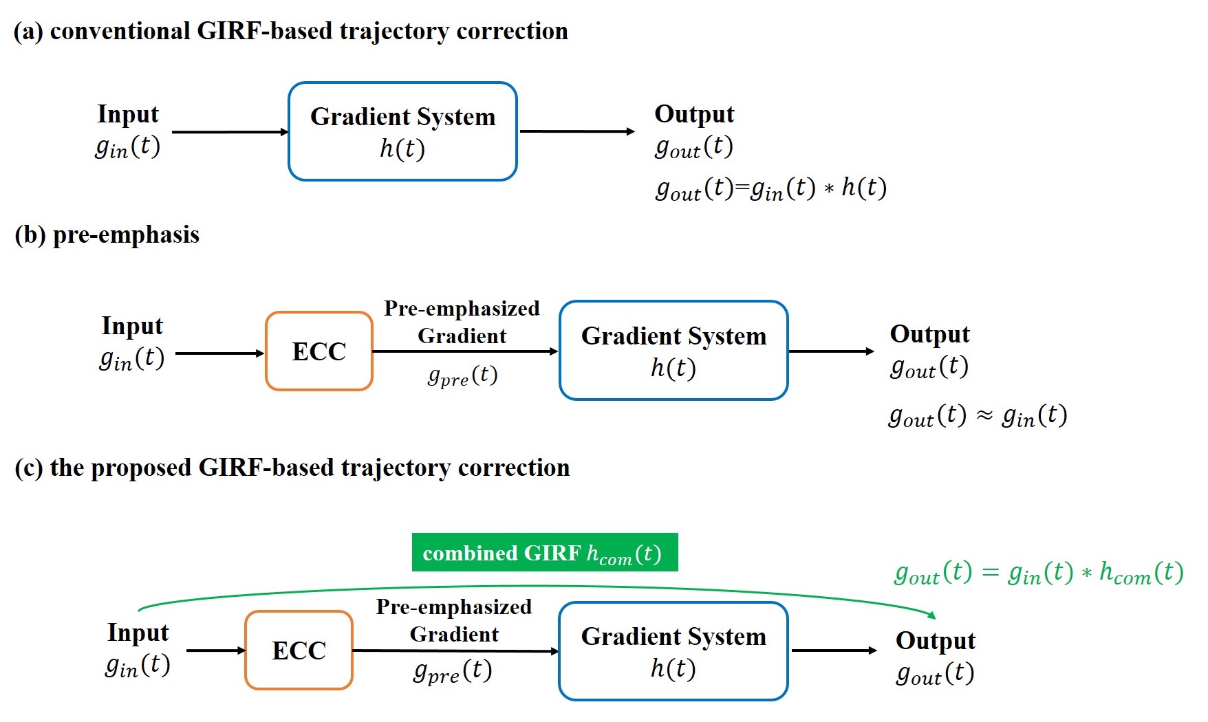
Figure 1: The schematic diagram of our proposed GIRF-based correction method.
(a) Conventional GIRF-based trajectory correction. GIRF $$$h(t)$$$ can be measured using a phantom or field probes.
(b) Pre-emphasis is performed to modify the designed waveform and the gradient outputs would be closer to the nominal gradients.
(c) Our proposed trajectory correction method. The proposed combined GIRF $$$h_{com}(t)$$$ including the pre-emphasis operation and the characteristic of the gradient chain can be used to further correct the spiral trajectory.