4958
Development of a Multichannel Transmit Array for Knee Arterial Spin Labeling Imaging at 7 Tesla1Center for Magnetic Resonance Research, University of Minnesota, Minneapolis, MN, United States
Synopsis
Keywords: RF Arrays & Systems, Arterial spin labelling
Motivation: To overcome the limitations of a commercially-available single-transmit channel knee coil in terms of B1+ inhomogeneity in the imaging region, and limited coverage in the proximal femoral meta-diaphysis for knee bone marrow arterial spin labeling (ASL) at 7T.
Goal(s): Our goal was to evaluate the B1+ performance of possible transmit array designs, as the first step towards an optimized design for an ASL imaging knee coil.
Approach: 6- and 8-channel multichannel transmit array designs were explored experimentally and in simulation.
Results: Both evaluated transmit arrays provided more uniform B1+ and better coverage in the labelling region compared to a single-transmit channel knee coil.
Impact: Development of pTx-capable knee coils will greatly improve the quality, reliability, and efficiency of knee ASL imaging at 7T and can provide the clinically critical but currently not available platform for the assessment of knee bone marrow perfusion.
Introduction
Although ultrahigh field (UHF) MRI can improve knee bone marrow arterial spin labelling (ASL) (called knee ASL imaging to be brief) and signal-to-noise ratio (SNR), the expected benefits can only be realized after overcoming existing technical challenges and limitations1,2. For optimal perfusion SNR efficiency, knee ASL imaging requires a large B1+ coverage along the z-axis for a sufficiently high and a relatively homogeneous B1+ field for adiabatic inversion RF pulses of the FAIR3 method, as well as a uniform transverse B1+ field in the targeted knee bone marrow area for imaging readouts4. As also demonstrated here, the standard single-channel transmit knee coil cannot satisfy these requirements of knee ASL imaging at 7T.Based on experience from our previously published efforts5 we propose to develop a parallel transmit (pTx)-capable coil with an optimal configuration for knee ASL imaging. One possible configuration would consist of 16-channel Transmit (Tx), 24- or 32-channel Receive (Rx) array using loop-dipole elements (Fig 1) to produce the needed B1+ coverage, uniformity, and SAR efficiency in the more proximal femur for spin labelling while also improving B1+ homogeneity in the imaging region. An integrated high-density receive array in the knee region may also need to provide high SNR perfusion images and facilitate highly accelerated parallel or simultaneous multi-slice imaging acquisition.
As a critical first step, we performed both simulations and experimental studies to evaluate the performance of alternative coil configurations. Here we will report the results from our evaluations of knee coils using 6- and 8-channel transmit/receive (Tx/Rx) fractionated dipole arrays6,7 and a single-channel transmit knee coil to get an insight into the B1+ performance of these coils that will facilitate the final design of our 7T pTx-capable knee ASL Imaging coil.
Methods
Experimental studies were performed on a Siemens 7T Terra whole-body MRI scanner equipped with 16 independent 2kW RF power amplifiers and 64 receivers. The 6- and 8-channel fractionated dipole arrays were built onto a 40 cm long conically-shaped 3D printed former (Fig 2 A-D). The dipole elements were implemented based on the original design by Raaijmakers et al8.Two 3D resin-printed phantoms were used for our studies (Fig 2). The first was ~50cm long, conically-shaped (Fig 2E), and filled with a polyvinylpyrrolidone (PVP) solution having dielectric properties (297MHz to be σ=0.56 S/m and Ɛr=51.6) to match that of the human tissue at 7T. The second phantom was ~40cm long, leg-shaped (Fig 2F), and filled with the same PVP solution.
Small flip angle calibration scans9 and actual flip angle imaging (AFI) acquisitions10 were performed to facilitate the assessment of B1+ performance and the longitudinal coverage of each coil with the coils loaded with the conically-shaped phantom, as well as the 8-channel dipole array loaded with leg-shaped phantom.
With our implemented 8 channel dipole array coil, single-shot fast spin echo (ss-FSE) imaging as in previous studies1,2 was performed to demonstrate the ability of mitigating B1+ inhomogeneity in targeted imaging regions, and anatomic GRE imaging to assess the increased imaging overage under CP mode with a 2-mm isotropic resolution, 2-fold in-plane acceleration, 2.63-ms TE, 80-ms TR and chemical shift fat saturation.
Results
Simulated B1+ maps (Fig 3) from the 6-channel dipole array demonstrate mean B1+ efficiency of 0.28 µT/ (W)0.5, peak B1+ per 1 watt input power of ~0.51µT, and a coefficient of variation (CoV) of 27%, while the 8-channel dipole array demonstrate a mean B1+ efficiency of 0.27µT/ (W)0.5, a peak B1+ per 1 watt input power of ~0.42µT, and a CoV of 21%. Peak 10 g SAR levels were 0.35W/kg with the 6-channel, and 0.29W/kg for 8-channel array with 1 W input power. Combining those performance metrics, we find mean SAR efficiency of the 6-channel array to be 0.48µT/ (W/kg)0.5, and 0.50µT/ (W/kg)0.5 for the 8-channel array.Figure 4 shows B1+ maps obtained under circularly polarized (CP) mode and after B1+ optimization within the desired labelling region11. B1+ Maps and ss-FSE images of the knee epiphyseal bone marrow acquired under CP mode and after B1 shimming are presented in Figure 5 (C,D), and the anatomical GRE images with 2mm-isotropic resolution from a healthy volunteer are shown in Figure 5 (E-G) using GRE with fat saturation.
Conclusion
Our study results have demonstrated the improved B1+ performance of multi-channel dipole arrays to address knee ASL imaging needs. Our future work will include the addition of an integrated RF shield, which is needed to shield signal generated by the subject’s other leg, safety validation for both arrays, and a high density receive-only array to improve SNR during acquisition.Acknowledgements
This study was supported by National Institute of Health R56EB033365, 1R01EB033365, and P41 EB027061, S10 OD025256References
1 Li, X., Johnson, C. P. & Ellermann, J. Measuring Knee Bone Marrow Perfusion Using Arterial Spin Labeling at 3 T. Sci Rep 10, 5260, doi:10.1038/s41598-020-62110-y (2020).
2 Li, X., Johnson, C. P. & Ellermann, J. 7T bone perfusion imaging of the knee using arterial spin labeling MRI. Magnetic resonance in medicine : official journal of the Society of Magnetic Resonance in Medicine / Society of Magnetic Resonance in Medicine 83, 1577-1586, doi:10.1002/mrm.28142 (2020).
3 Kim, S. G. Quantification of relative cerebral blood flow change by flow-sensitive alternating inversion recovery (FAIR) technique: application to functional mapping. Magn Reson Med 34, 293-301, doi:10.1002/mrm.1910340303 (1995).
4 Li X, Johnson CP, Ellermann J, Metzger GJ. Evaluation of Potential Benefits of 7T for Knee Epiphyseal Bone Marrow ASL Imaging. Proc. Intl. Soc. Mag. Reson. Med. 2023: 0135.
5 Waks, M. et al. in Proceedings of the 30th ISMRM Conference 4107.
6 Raaijmakers, A. J. et al. The fractionated dipole antenna: A new antenna for body imaging at 7 Tesla. Magnetic resonance in medicine : official journal of the Society of Magnetic Resonance in Medicine / Society of Magnetic Resonance in Medicine 75, 1366-1374, doi:10.1002/mrm.25596 (2016).
7 Eryaman, Y. et al. Radiofrequency heating studies on anesthetized swine using fractionated dipole antennas at 10.5 T. Magn Reson Med 79, 479-488, doi:10.1002/mrm.26688 (2018).
8 Raaijmakers, A. J. et al. Design of a radiative surface coil array element at 7 T: the single-side adapted dipole antenna. Magnetic resonance in medicine : official journal of the Society of Magnetic Resonance in Medicine / Society of Magnetic Resonance in Medicine 66, 1488-1497, doi:10.1002/mrm.22886 (2011).
9 Van de Moortele, P. F. et al. B(1) destructive interferences and spatial phase patterns at 7 T with a head transceiver array coil. Magnetic resonance in medicine : official journal of the Society of Magnetic Resonance in Medicine / Society of Magnetic Resonance in Medicine 54, 1503-1518, doi:10.1002/mrm.20708 (2005).
10 Yarnykh, V. L. Actual flip-angle imaging in the pulsed steady state: a method for rapid three-dimensional mapping of the transmitted radiofrequency field. Magnetic resonance in medicine : official journal of the Society of Magnetic Resonance in Medicine / Society of Magnetic Resonance in Medicine 57, 192-200, doi:10.1002/mrm.21120 (2007).
11 Li, X., Auerbach, E. J., Van de Moortele, P. F., Ugurbil, K. & Metzger, G. J. Quantitative single breath-hold renal arterial spin labeling imaging at 7T. Magnetic resonance in medicine : official journal of the Society of Magnetic Resonance in Medicine / Society of Magnetic Resonance in Medicine 79, 815-825, doi:10.1002/mrm.26742 (2018).
12 Erturk, M. A., Raaijmakers, A. J., Adriany, G., Ugurbil, K. & Metzger, G. J. A 16-channel combined loop-dipole transceiver array for 7 Tesla body MRI. Magnetic resonance in medicine : official journal of the Society of Magnetic Resonance in Medicine / Society of Magnetic Resonance in Medicine 77, 884-894, doi:10.1002/mrm.26153 (2017).
Figures
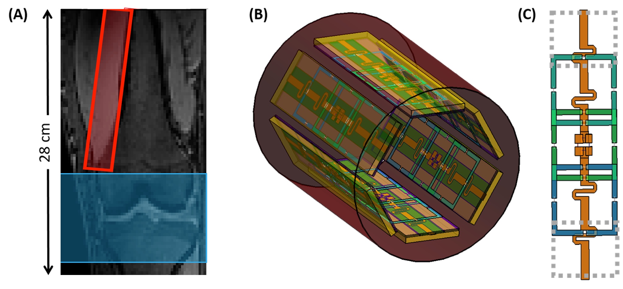
Figure 1: Illustration of labeling (red) and imaging (blue) regions (A) in knee ASL imaging and the concept model of a multi-channel transceiver knee coil consisting of loop dipole elements similar to that used in our 7T body imaging (B) along with the model of an loop-dipole element (C)12.
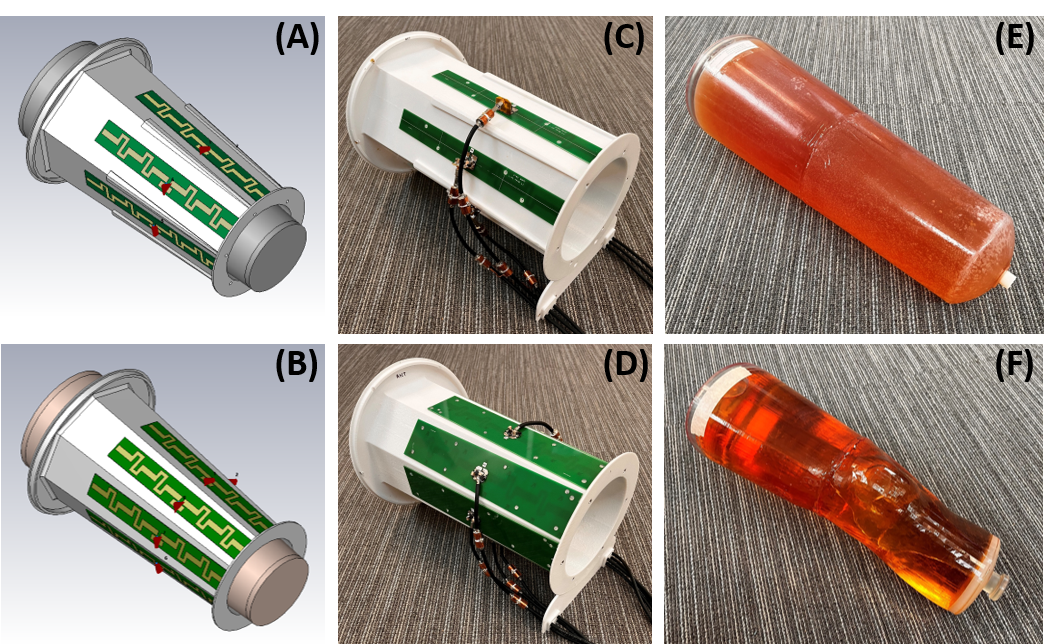
Figure 2: The simulated and fabricated 6-channel (A & C) and 8-channel (B & D) fractionated dipole arrays are shown, along with the ~50 cm long conical-shaped phantom (D) filled with a polyvinylpyrrolidone (PVP) solution (σ=0.56 S/m; Ɛr=51.6 at 297MHz) to match that of the human leg tissue at 7T and the ~40 cm long leg-shaped phantom (E) with two compartments: one outside the bone filled with the same PVP solution and another inside the bone filled with peanut oil to mimic bone marrow fat.
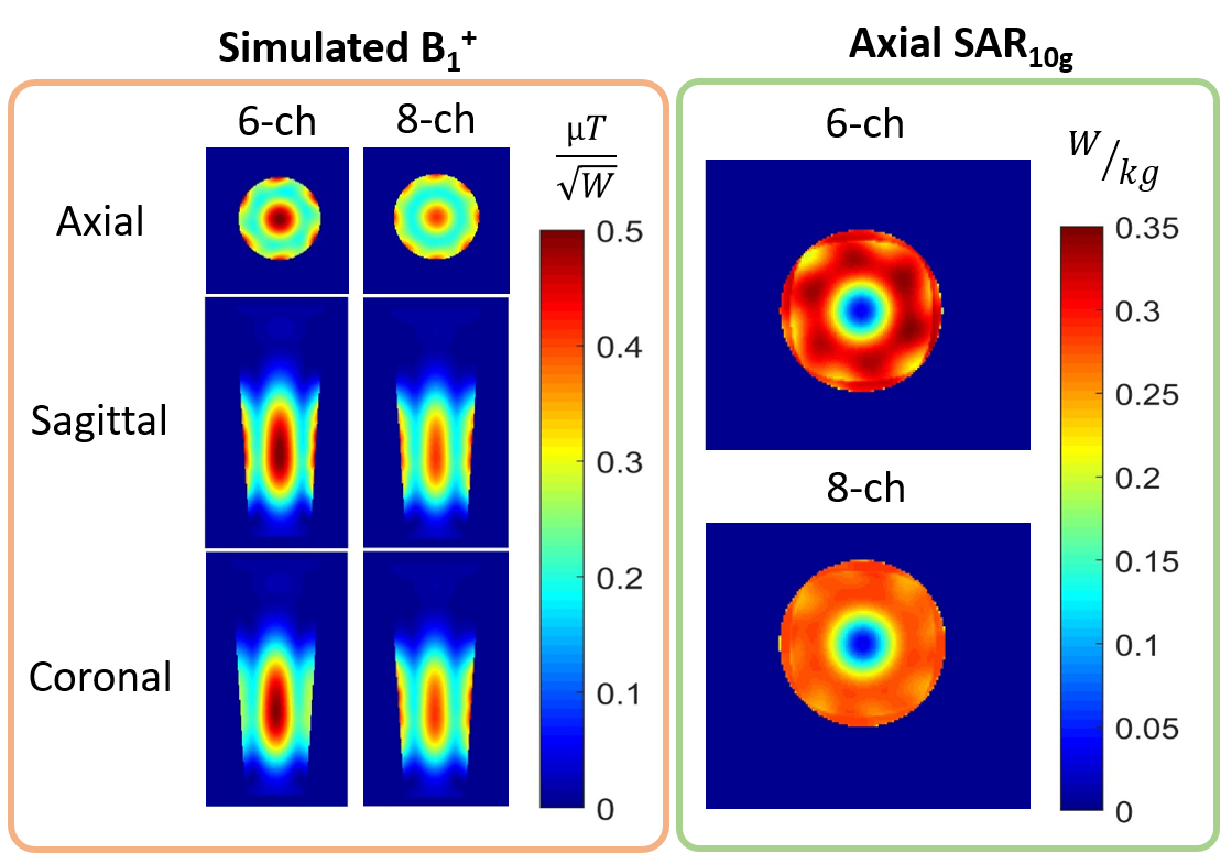
Figure 3: Simulated circularly polarized B1+ fields (Left) and simulated peak 10g SAR per 1 watt input power (Right) in a uniform PVP-filled conical-shaped phantom for both the 6- and 8-channel fractionated dipole arrays.
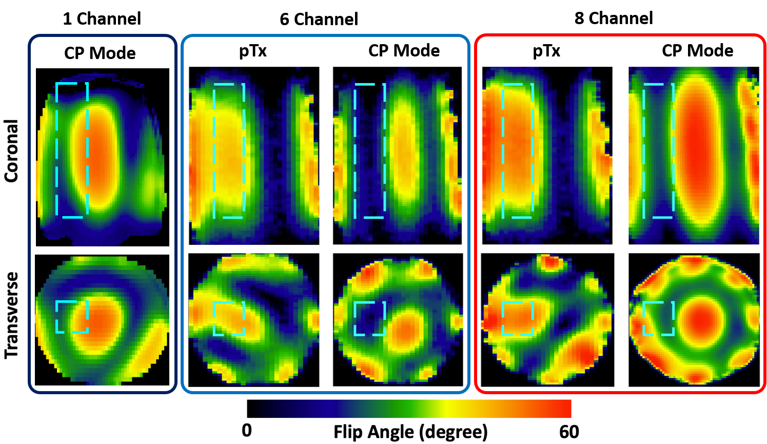
Figure 4: Experimental B1+ maps with (Left) single-channel transmit coil, and both the (Center) 6- and (Right) 8-channel dipole arrays in CP mode and after B1+ optimization using trade-off B1+ shimming solutions for the ASL region (indicated by dashed blue box) in a uniform PVP-filled conical-shaped phantom. The optimized B1+ fields provide increased homogeneity and z-coverage compared to that of the single-channel transmit coil, as well as both arrays in CP mode.
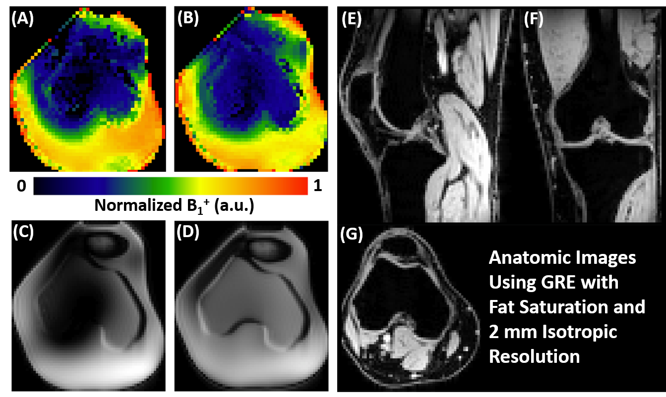
Figure 5: Results to demonstrate the ability to mitigate B1+ inhomogeneity in bone marrow with the 8-channel coil in the leg-shaped phantom with B1+ maps and single-shot fast spin echo images for both (A) CP mode and (B) after B1+ shimming optimization, and to increase foot-heed imaging coverage by the 8-channel coil for anatomical imaging in a healthy volunteer under a CP mode with a 2-mm isotropic resolution, 2-fold in-plane acceleration, 2.63-ms TE, 80-ms TR and fat suppression (E-G).