4949
7T MRI Coils: Streamline Approach in Analysis of Coil Coupling1Electrical Engineering, Eindhoven University of Technology, Eindhoven, Netherlands
Synopsis
Keywords: High-Field MRI, RF Arrays & Systems, Coupling
Motivation: To gain a better understanding of electromagnetic (EM) interactions in RF coil designs by visualizing their EM flow.
Goal(s): Identifying the dominant coupling mechanism in different coil types through visualization of electric and magnetic fields and power flow.
Approach: Simulating conventional, shielded-coaxial-cable (SCC), twisted pair coils, and square loops (self-decoupled coils) to visualize their EM fields using streamlines.
Results: Diverse coupling behaviors are observed among the coil types, each demonstrating unique dominant mechanisms. A high resemblance in the EM flow between the self-decoupled coil and the SCC and twisted pair coils was found.
Impact: Identifying the dominant coupling mechanism in different coil designs with streamlines can help in adjusting the coil design for maximum interelement decoupling when placed in an array configuration.
Introduction
At ultra-high field MRI, interelement coupling in multichannel arrays can lower the performance of the array [1-3]. Therefore, it is important to identify the dominant coupling mechanism of individual coil elements which can help in adjusting the coil design for reduced coupling. We propose the streamline approach for visualization of the electromagnetic (EM) fields and power flow in the presence of two coil elements. This method was used in the wireless power transfer field [4] but for the opposite problem – to maximize power transfer between two coils. We analyzed conventional, shielded-coaxial-cable (SCC) [5], twisted pair [6,7], and self-decoupled coils [8] with the streamline approach and we discussed their dominant coupling mechanism.Methods
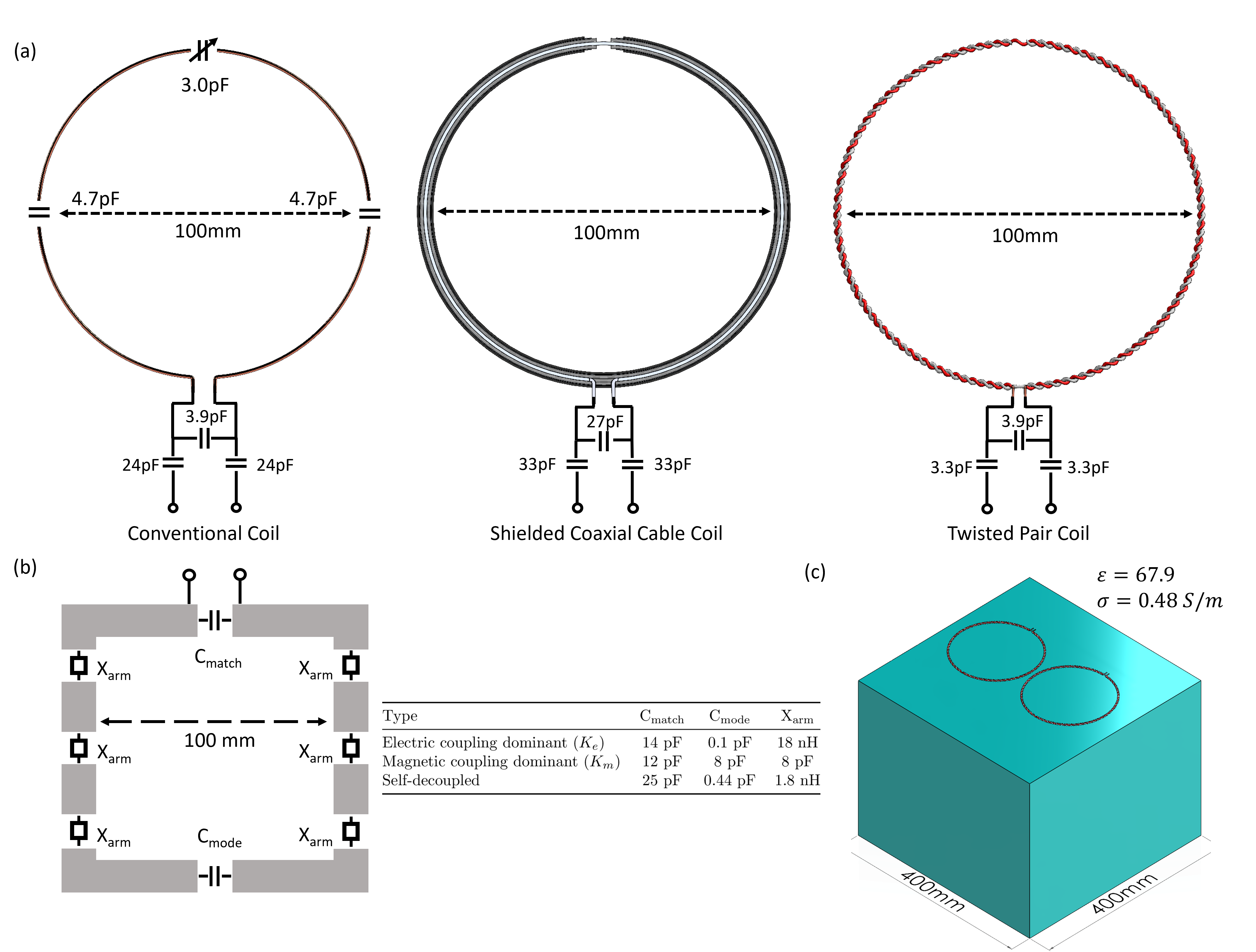
Three RF coils (conventional, SCC, and twisted pair, Fig.1(a)) had a diameter of 100mm and were tuned to 297.2MHz. The conventional loop coil was modeled as 1mm diameter copper wire, the SCC as the RG58 coaxial cable, and the twisted pair as twisting two 18 gauge PTFE insulated copper wires. The self-decoupled coils, designed following [8], are detailed in Fig.1(b) with the dimensions and lumped element values for the different configurations. In the simulation setup, two coils of each kind are placed at a distance of 10mm from each other and at a 40mm distance from the homogeneous cubic phantom (Fig.1(c), 400x400x400mm3, $$$\varepsilon_r$$$=67.9, $$$\sigma$$$=0.48 S/m). We performed additional simulations where the conventional, SCC, and twisted pair coils were placed closer to the phantom, at 20mm distance. Electromagnetic simulations were performed in CST Microwave Studio 2023 (Dassault Systèmes, France).We will use streamlines to visualize the EM fields of the coil [4] and use equations (11), (14) & (15) from [9] for calculating the electric ($$$K_e$$$), magnetic ($$$K_m$$$), and total coupling ($$$K_{total}$$$). To determine $$$K_e$$$ and $$$K_m$$$, simulations were conducted with a single coil, where an electric and magnetic wall was placed at the symmetry plane between the two coils [9,10].
Results and Discussion
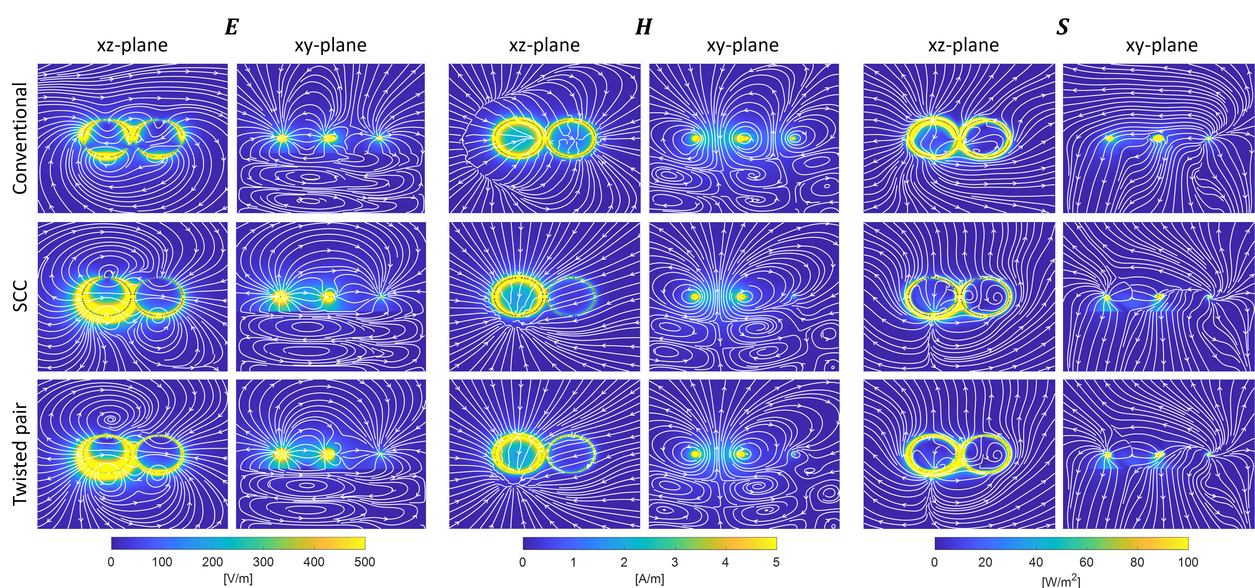
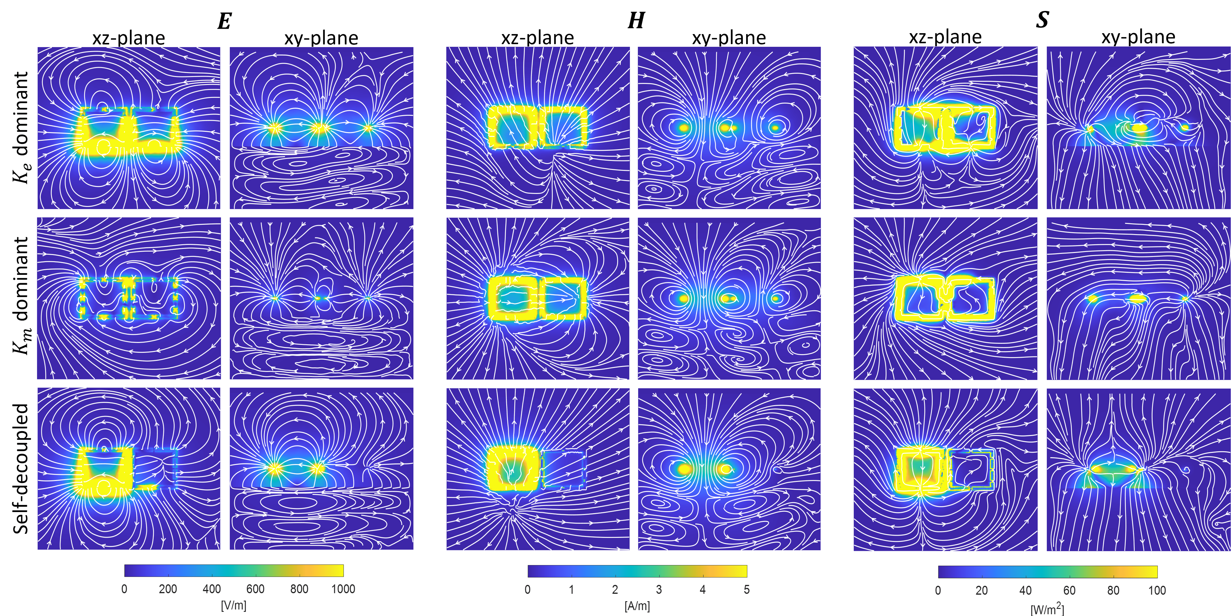
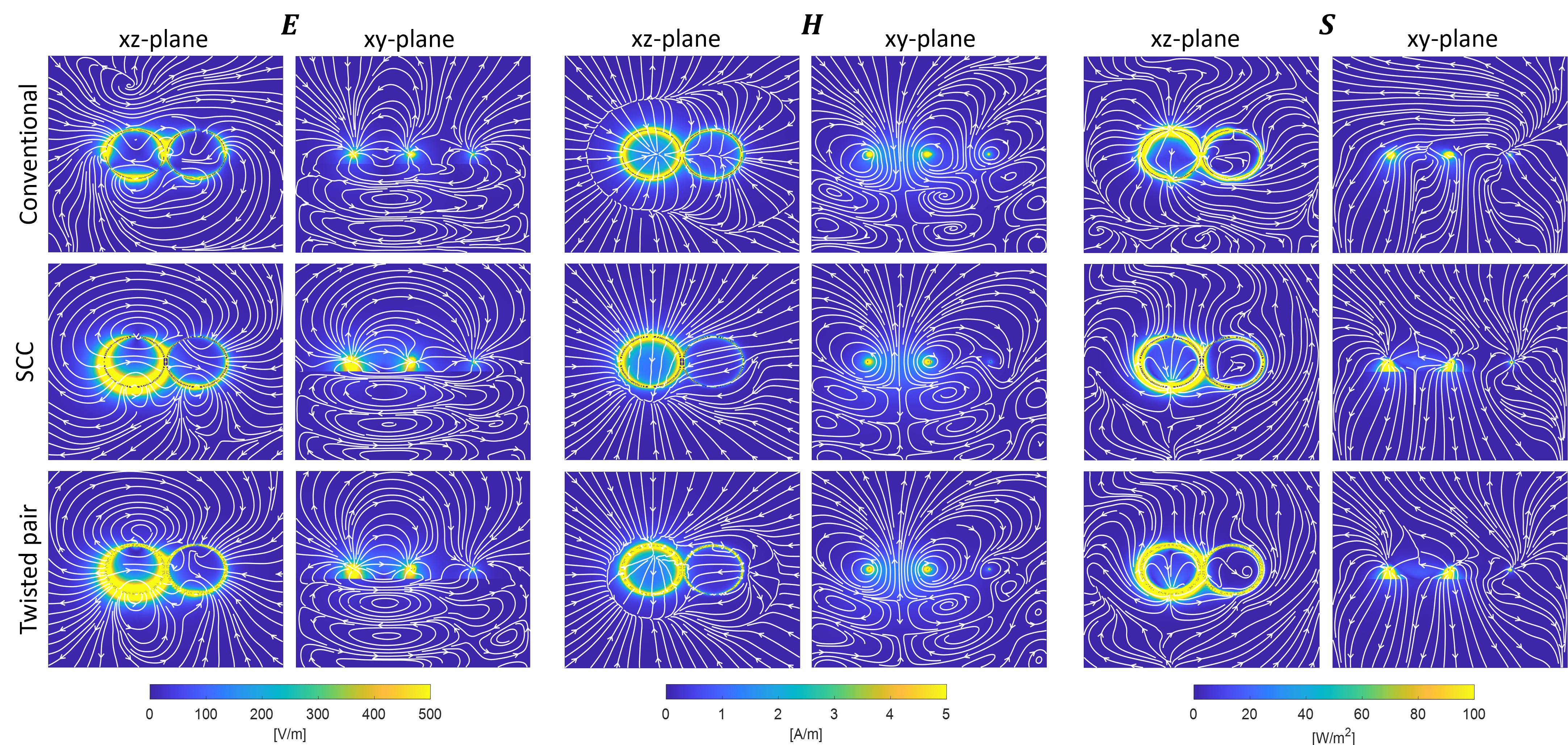
Fig.2 shows the streamlines of the electric (E), magnetic (H), and Poynting vector (S) fields calculated for the conventional, SCC, and twisted pair, and Fig.3 shows the same for the self-decoupled coils. Self-decoupled coils were designed for three scenarios: dominant electric coupling, dominant magnetic coupling, and decoupled coils. Conventional coils primarily exhibit magnetic coupling, reflected in similar streamlines to the $$$K_m$$$ dominant square loops. The characteristic of magnetic field coupling dominance is the appearance of magnetic field ‘’bubbles’’ around coils (Fig.2&3) which increases when coils are closer to the phantom (Fig.4). The size of magnetic field ‘’bubbles’’ shows the amount of magnetic field which is coupled to the coil versus the radiated field (lines are pointing away). Examining the xy-plane, numerous magnetic field lines go through the center of the second coil, resulting in increased magnetic flux and consequently, a higher induced current and increased coupling. Passive SCC, twisted pair, and self-decoupled coils demonstrate 'transparency' to magnetic fields.SCC and twisted pair coils predominantly display electric coupling, with visible electric field lines initiating from the active coil and ending at the passive coil (Fig.2). The simulated coils in Fig.2&3 are 40mm away from the phantom, whereas in Fig.4 they are 20mm away. Increased coupling 'through' the phantom is observed. Induced dielectric displacement currents in the phantom produce an additional magnetic field, causing the magnetic field 'bubble' to expand.
Calculated coupling coefficients, as per [8,9] and presented in Table 1, align well with conclusions drawn from the streamline analysis. The reported $$$S_{21}$$$ parameters correspond closely to the coupling coefficient results. The total coupling being $$$K_{tot}$$$<0 and $$$K_e$$$>$$$ K_m$$$ in both transmission line coils highlights the dominance of capacitive coupling between the coils [6]. In the case of the conventional coil, where $$$K_{tot}$$$ >0and $$$K_e$$$<$$$ K_m$$$, inductive coupling prevails, consistent with the observations in Fig.2&4, where a large magnetic field bubble is introduced by the second coil.
When analyzing the power flow, the second coil receives minimal power in the case of the SCC, twisted pair, and self-decoupled coils. Streamlines in this scenario reveal that the power flows outward from the active coil, towards the phantom and free space, with limited interactions with the passive coil.
Conclusion
The streamline approach can help in identifying the dominant coupling mechanism of the coils. It is shown in [4] that coil impedance dictates the power flow. That can be interpreted as an adjustment of a coil design for controllable power and electromagnetic field flow in order to minimize coupling between the coil elements. That implies also the possibility of using different coil elements in an array configuration for minimum coupling.Acknowledgements
No acknowledgement found.References
[1] Avdievich, N. I. et al. (2018). Decoupling of a double‐row 16‐element tight‐fit transceiver phased array for human whole‐brain imaging at 9.4 T. NMR Biomed, 31(9), e3964.
[2] Wu, B. et al. (2006). Design of an inductively decoupled microstrip array at 9.4 T. JMR, 182(1), 126-132.
[3] Roemer, P. B. et al. (1990). The NMR phased array. MRM, 16(2), 192–225.
[4] Shamonina, E. et al. (2021). On wireless power transfer between coils in the presence of radiation. J Phys D: Appl Phys, 54(40), 405502.
[5] Ruytenberg, T. et al. (2020). Shielded-coaxial-cable coils as receive and transceive array elements for 7T human MRI. MRM, 83(3), 1135–1146.
[6] Maravilla, J. A. et al. (2023). 15-Channel Head Cap Array using Twisted-Pair Elements for MRI. Proc. ISMRM (2023), Toronto, p 3733.
[7] Vliem, J. et al. (2023). Twisted Pair Transmission Line Coil -- A Flexible, Self-Decoupled and Extremely Robust Element for 7T MRI. arXiv preprint arXiv:2306.08934.
[8] Yan, X. et al. (2018). Self-decoupled radiofrequency coils for magnetic resonance imaging. Nat. Com., 9(1).
[9] Chu, Q. X. & Wang, H. (2008). A compact open-loop filter with mixed electric and magnetic coupling. IEEE Trans Microw Theory Tech, 56(2), 431–439.
[10] Hong, J. et al. (1996). Couplings of microstrip square open-loop resonators for cross-coupled planar microwave filters. IEEE Trans Microw Theory Tech, 44(11), 2099–2109.
Figures