4947
A Next Generation Surface Array For Body Imaging at 7T1University of Minnesota, Minneapolis, MN, United States
Synopsis
Keywords: RF Arrays & Systems, High-Field MRI
Motivation: Improved RF coil performance is needed to realize the gains from UHF body imaging.
Goal(s): Design a 7T body array with improved stability and increased transmit/receive performance.
Approach: A 32 channel loop-dipole (32LD) array was constructed with a shield allowing for on board electronics. Dipoles were transceivers while loops were coupled in groups of three on transmit while receiving separately. Comparisons were made with an existing 16LD array.
Results: The 32LD is more stable, has a lower flatter z-profile on transmit, 20% higher central SNR and supports parallel imaging on all axes
Impact: The new 32LD array provides a more robust platform for clinical translation of UHF body imaging while approaching the theoretical gains in SNR and improved parallel imaging performance enabling increased spatiotemporal resolutions at 7T.
Introduction
Recent FDA approval of clinical 7T MRI for head and knee imaging heralds a new era for ultra high field MRI as it moves towards becoming a more common clinical tool benefiting from increased signal to noise ratios1. However, challenges remain in realizing the full potential of these systems, especially in designing RF transmit and receive coils. We propose a new 16Tx/32Rx loop-dipole transceiver array (32LD).Methods
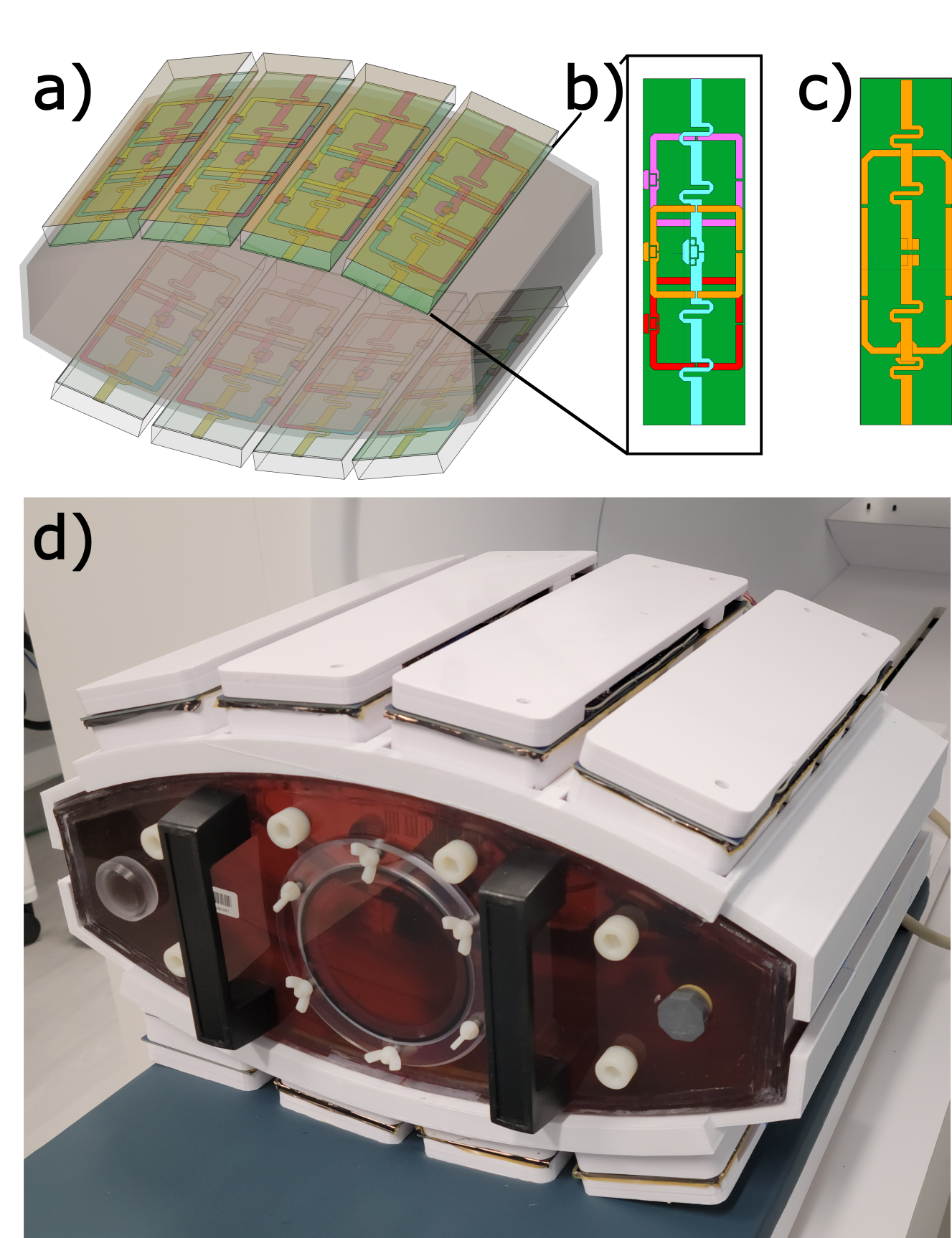
The 32LD array was constructed and compared against an existing 16 channel loop-dipole array2 (16LD) (Figure 1). The new array consists of 24 loops and 8 dipoles3,4 divided into 8 blocks where each block consists of 3 loops and a dipole. In addition to the antenna elements, each block has a novel RF shield to allow for on board active electronics and increased robustness to top loading. The RF shield was constructed from a two-sided flexible PCB with 9µm copper thickness and 25µm substrate thickness and placed 2 cm from the antennas. Fingers 12mm in width, separated by 1mm slots, were etched in the shield to minimize eddy currents5. On the transmit side, the 3 loops on each block were array-compressed6 down to a single effective loop via a 3-way Wilkinson power divider7 and optimized phase shifters.
Array-compression optimization: To determine the optimal phase to implement for the three compressed loops, the loss function shown in (1) was created and minimized for a single block. The coefficient of variation (CV) regularizer (λ) was empirically chosen to be 0.1.
$$$\min_{x}\left(\sum_{r\in{Mask}}1-\frac{B_1\left(r\right)\cdot{x}}{\mid{B}_1\left(r\right)}\right)+\lambda\cdot{CV}\left(B_1\cdot{x}\right)~~~~~~~~~~$$$ (1)
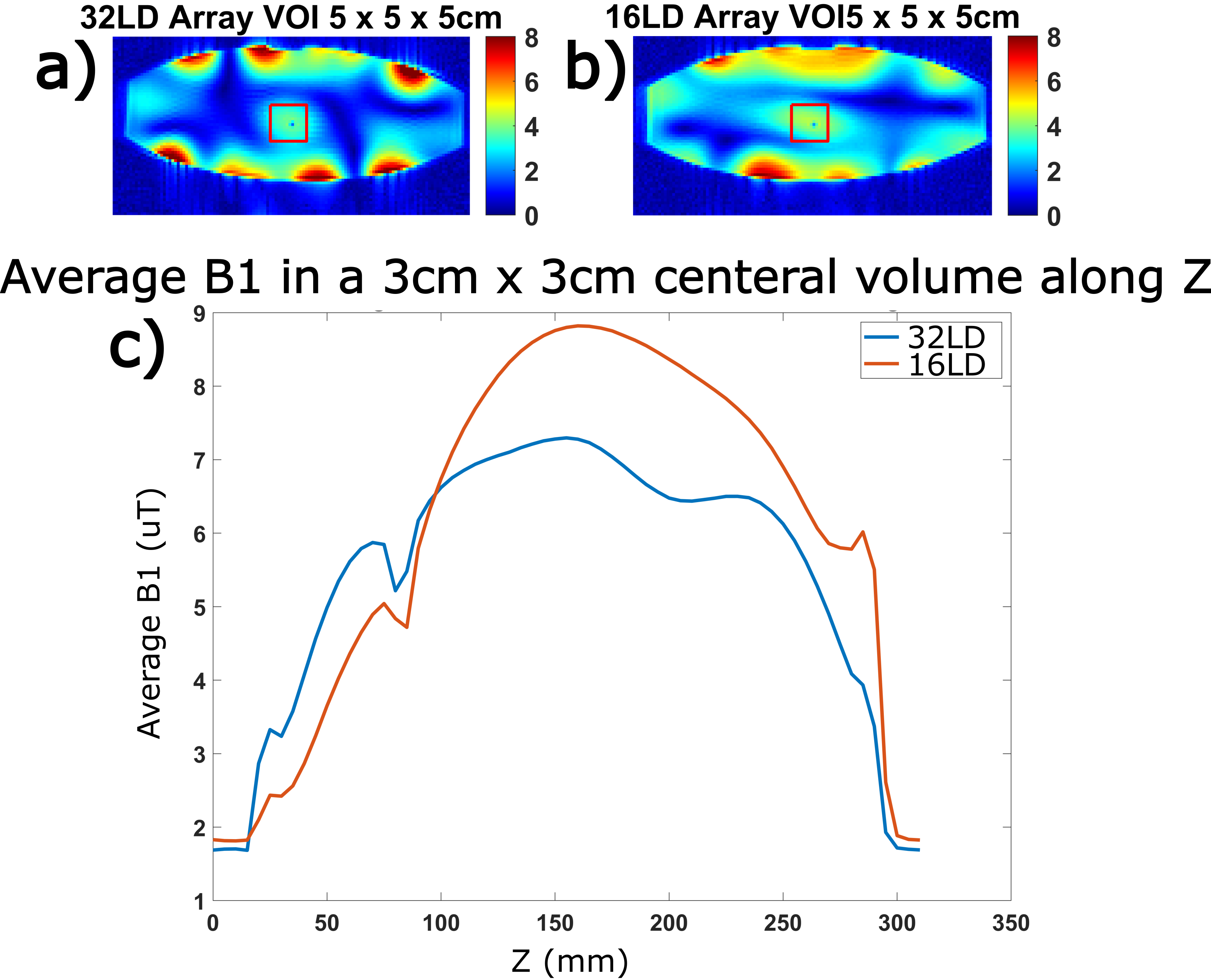
pTx Performance Comparison: To compare the pTx performance of the 32LD and 16LD arrays, 2D multi-slice B1 relative scans were acquired to obtain relative transmit (B1+) and receive (B1-) profiles8 and scaled to μT/V maps via an AFI acquisition9. A local efficiency shim was calculated maximizing the magnitude of sum over the sum of magnitude B1+ fields in a 5x5x5 cm3 volume and transmit efficiency was evaluated (Figure 2).
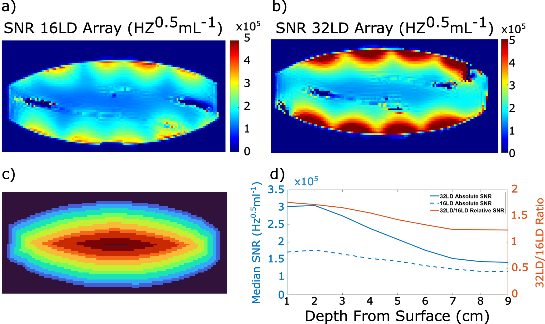
SNR Analysis: To measure SNR, an AFI, proton density weighted GRE, and noise scan were collected and used to calculate normalized SNR maps for each coil10. These SNR maps were then analyzed with 1cm concentric depths to compare the 32LD to the 16LD (Figure 3).
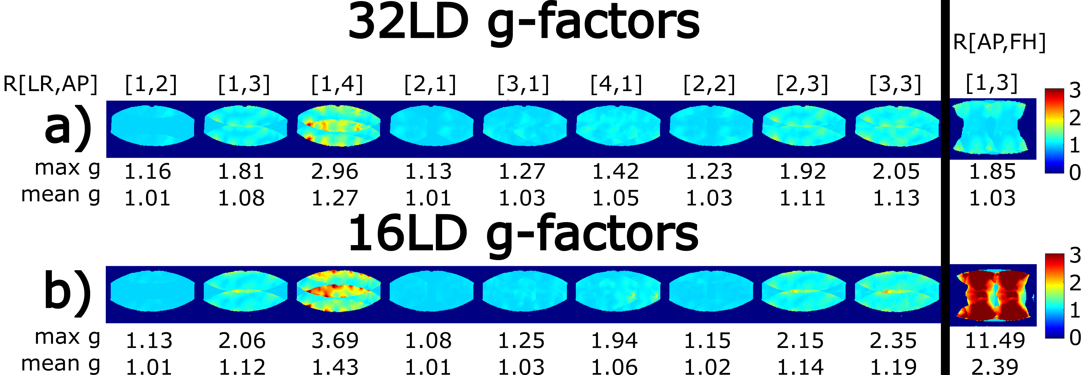
Parallel Imaging Performance: Parallel imaging performance was evaluated using a fully sampled 3D GRE images and retrospectively downsampled with different patterns and g-factor maps were calculated for each of the different patterns (Figure 4).
Results
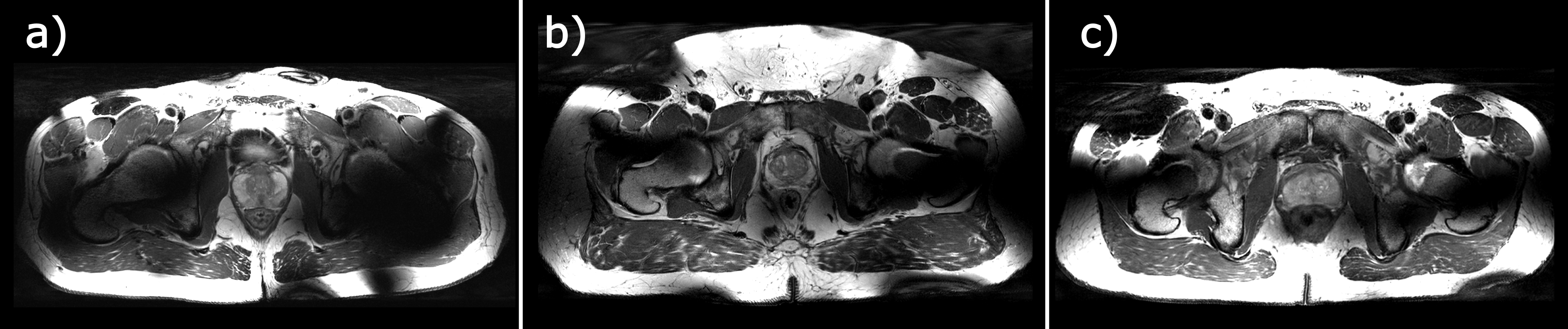
The 32LD has better SNR (Figure 3) and parallel imaging (Figure 4) performance as compared to the 16LD. The 16LD had a greater central B1+/V efficiency while the 32LD had a flatter B1+/V profile along the FH direction (Figure 2). This array was validated11 and accepted by an internal safety committee and preliminary in-vivo images were acquired in three volunteers (Figure 5).Discussion
While the 16LD has a higher central B1+/V efficiency, the 32LD was shown to have a flatter B1+ profile in the head-foot dimension. As this coil is often placed blind with respect to the anatomy of interest the flatter profile increases usability. The increased SNR brings us closer to expected gains at 7T and will benefit applications throughout the torso. While only slightly better in the LR and AP directions, parallel imaging performance was greatly improved as expected in the HF direction providing greater flexibility to accelerate acquisitions. Finally, while the shield may be the cause for observed decrease in transmit efficiency, it was a design choice which had clear advantages. The shield is uniquely placed between the antenna elements and active electronics with penetrations through the shield to route transmit and receive signals to and from the electronics. With most cabling routed behind the shield, coupling of the cables with the transmitted RF is greatly minimized, reducing cable currents and enhancing stability to patient motion12. Future studies will focus on assessing the full pTx functionality of the array while evaluating SAR efficiency (B1+/SAR0.5), an important metric related to SNR efficiencyConclusion
A 7T proton body array was created that has better intrinsic SNR and an additional dimension that can be used for parallel imaging. These performance improvements will allow for more robust clinical imaging due to its larger field of view, higher SNR, and increased parallel imaging flexibility.Acknowledgements
Funding was provided by NIH P41 EB027061 and NIH R01 EB029985.References
Ertürk, M. A., et. Al., Evolution of UHF Body Imaging in the Human Torso at 7T Technology, Applications, and Future Directions . (2019) Top Magn Reson Imaging 28 , 101 124.
Ertürk, A., et. a l. A 16 channel combined loop dipole transceiver array for 7 Tesla body MRI .
(2016) MRM 77 , 884 894
Balanis, C.A. Antenna Theory: Analysis and Design. 3rd Ed. New York: Wiley, 2005
The Fractionated Dipole Antenna: A New Antenna forBody Imaging at 7 Tesla
Lechner-Greite, S., Hehn, N., Werner, B., et al. Minimizing eddy currents induced in the ground plane of a large phased-array ultrasound applicator for echo-planar imaging-based MR thermometry. J. Ther. Ultrasound, 2016; 4(1):1-14
Cao, Z., Yan, X. and Grissom, W.A. (2016), Array-compressed parallel transmit pulse design. Magn. Reson. Med., 76: 1158-1169. https://doi.org/10.1002/mrm.26020
Wilkinson EJ. An N-way hybrid power divider. IEEE Trans Microwave Theory Tech 1960;20:116–118
Brunner, D., Pruessmann, K., SVD Analysis of Array Transmission and Reception and its Use for Bootstrapping Calibration. Magn Reson Med, 2016; 76(6):1730-1740.
Van de Moortele, P. F., Akgun, C., Adriany, G., Moeller, S., Ritter, J., Collins, C. M., ... & Uğurbil, K. (2005). B1 destructive interferences and spatial phase patterns at 7 T with a head transceiver array coil. Magn Reson Med, 54(6), 1503-1518
Pruessmann, K., Weiger, M., Scheidegger, M., Boesiger, P., SENSE: Sensitivity encoding for fast MRI, Magn Reson Med, 1999; 42(5):952-962.
Yarnykh, V.L. (2007), Actual flip-angle imaging in the pulsed steady state: A method for rapid three-dimensional mapping of the transmitted radiofrequency field. Magn. Reson. Med., 57: 192-200. https://doi.org/10.1002/mrm.21120
Schmidt, S., Ertürk, A., He, X., Haluptzok, T., Eryaman, Y., Metzger, G., Improved 1H body imaging at 10.5 T: Validation and VOP-enabled imaging in vivo with a 16-channel transceiver dipole array, Magn Reson Med, 2023.
Haluptzok, T., Lagore, R., Schmidt, S., Metzger, G., A Comparison Between Shielded and Unshielded RF Antennas for 7T Body MRI In proceedings of the 31st annual meeting of the ISMRM; 2023
Figures