4944
Field-based spatial self-registration of multi-coil hardware for B0 field control1Biomedical Engineering, Columbia University, New York, NY, United States, 2Radiology, Columbia University, New York, NY, United States
Synopsis
Keywords: System Imperfections, System Imperfections: Measurement & Correction
Motivation: Successful multi-coil B0 field control relies on reproducible hardware placement.
Goal(s): Our goal was to detect hardware misplacements from MC-generated field patterns alone (i.e. without field probes) to allow spatial transformations for correction.
Approach: We co-registered unique field maps before and after hardware displacements to derive the underlying translation and rotation parameters.
Results: In simulation and preliminary scanner validation, hardware misplacements were detected with sub-millimeter/sub-degree precision.
Impact: Field-based spatial self-registration for multi-coil field inserts is expected to allow optimal B0 field control even with differences in hardware placement, thus preserving the best shim performance.
INTRODUCTION
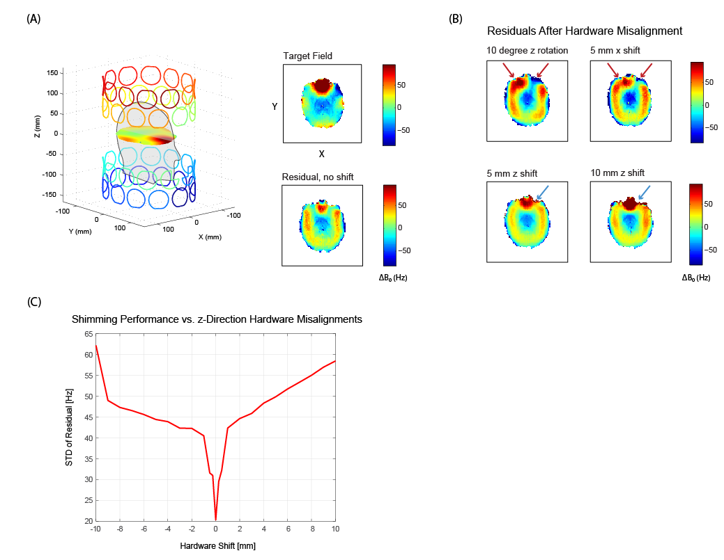
Acquisition of robust Magnetic Resonance Imaging (MRI) data relies on homogeneous B0 field conditions1. Susceptibility differences between air and tissue can create distortions of the B0 field, leading to image artifacts and signal dropout2. Multi-coil (MC) shimming systems using an array of individually-driven, generic, direct current coils as an alternative basis for B0 shimming3 have been demonstrated to outperform low order spherical harmonic shimming in the brain4,5. To date, MC setups have been designed as temporary inserts to existing MR scanners5–7. Basis fields for these inserts are acquired by a lengthy calibration process, and shim fields are calculated as a combination of calibrated basis fields for the subject/application at hand1. To accurately calculate shim fields, it is therefore essential to either position the hardware in precisely the same location as it was during its calibration or have exact knowledge of the current position relative to the calibration scenario. Indeed, large performance reductions in B0 field control are observed even for millimeter-scale displacements (Figure 1)5,8,9. We are currently developing an integrated MC/RF system for diagnostic imaging at 3T and aim to prevent any such losses in shim performance due to routine misalignments. Our purpose is to reliably detect misaligned hardware from a short single field map acquisition without the need of field probes, ensuring optimal performance of field-generating MC inserts.METHODS
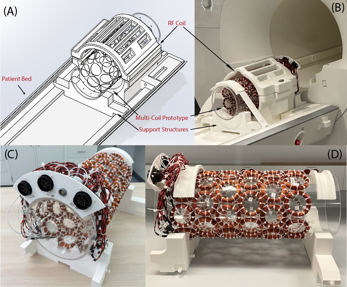
Multi-Coil ArrayThe field-based localization of MC hardware presented in this work was established via theoretical simulations and an MC array with 6 rows of 8 coils (diameter 70 mm, 100 turns) that were arranged on a cylindrical former (outer diameter 8.0 in, Figure 2).
Theoretical Hardware Localization
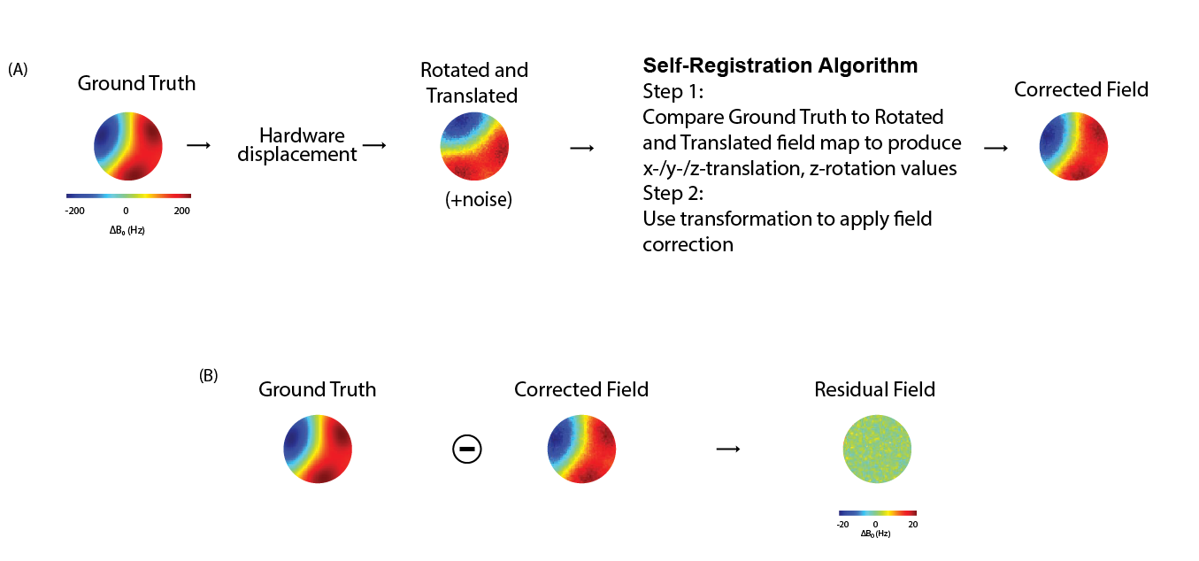
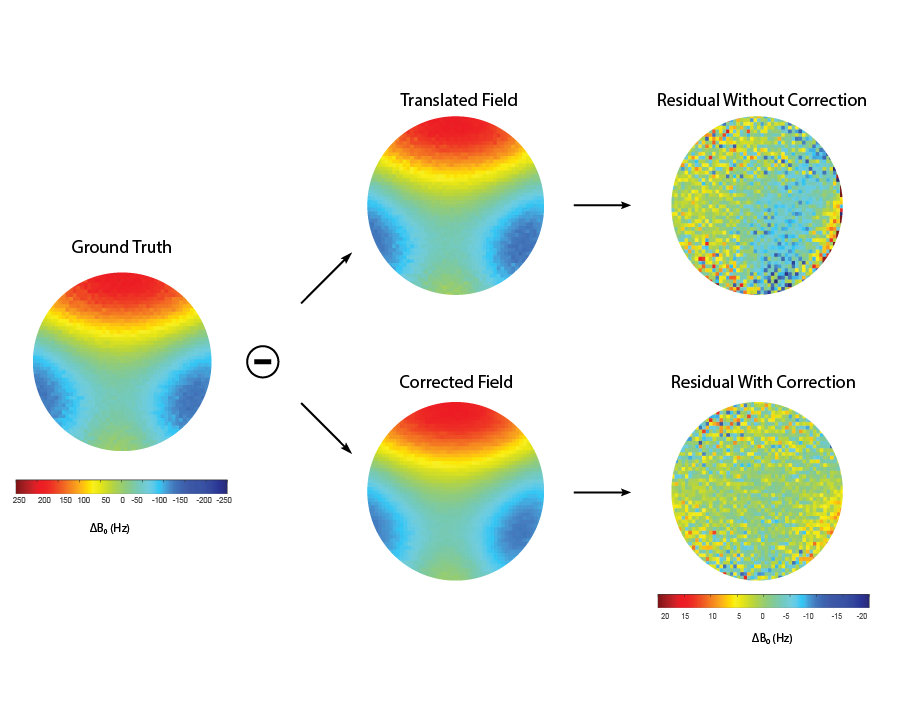
Individual B0 field shapes with the employed MC array were simulated using B0DETOX11,12. These basis maps were combined to generate a variety of Ground Truth fields, and hardware misplacements were realized as affine transformations. A least squares approach was used to derive an affine transformation for co-registration of the Ground Truth and Rotated/Translated fields and to output the necessary z-rotation and x-/y-/z- translational parameters. To quantify success, the reverse transformation was applied to the transformed fields, and the Residual was calculated by subtracting this Corrected Field from the Ground Truth (Figure 3).
Monte-Carlo Analysis of Algorithm Performance
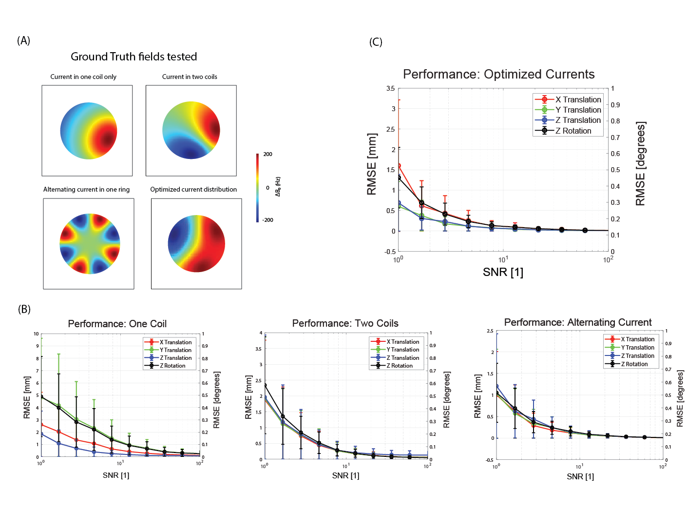
Monte Carlo simulations of combinations of x-, y-, and z-translations up to ±10 mm and z-rotations up to ±10 degrees were performed on the Ground Truth at SNR levels 1-100, and transformation parameters were retrieved by our co-registration algorithm. Root mean square error (RMSE) of the four parameters was calculated for each simulated shift, and resulting RMSEs were averaged for each SNR level.
Field Shape Optimization
This simulation approach was also used to determine which Ground Truth field yielded the highest localization accuracy and robustness. We iterated through all possible combinations of ±1% current on each coil of rows two and five and tested a random set of translation and rotations for each configuration. The Ground Truth field that yielded lowest combined errors was selected (Figure 4).
Preliminary Scanner Validation
The experimental implementation of the 48-channel MC hardware was realized on a 3T Siemens PRISMA scanner (Figure 2B-D). Coils were driven by a 64-channel amplifier (Resonance Research, Inc., Billerica, MA, USA) and a customized controller10. Using the optimized Ground Truth field, we compared field maps before and after misplacing the MC hardware.
RESULTS
In simulated data, for SNR levels above 12.92, translations and rotations were recovered with a norm error below 0.13 mm (95% Confidence Interval (CI): [0.09713, 0.12874]) and 0.10 degrees (95% CI: [0.07822, 0.10028]), respectively (Figure 4C).In scanner validation, the co-registration method was successfully able to recover known translation parameters with norm error under 1 mm and 1 degree. To quantify the improvement, a correction applied using the recovered parameters decreased the mean and standard deviation of the residual by 27.9% and 25.7% respectively across the volume. In a central slice, the standard deviation of residual decreased by 33.7%, from 22.26 Hz to 14.76 Hz (Figure 5).
DISCUSSION
Here we presented a method for MC hardware localization based on MC-generated B0 fields. Future plans include the further optimization of MC-derived B0 shapes for robust hardware localization in combination with accelerated B0 mapping protocols. We also plan to include x- and y-rotations which cannot be accounted for by rigid transformations alone but require qualitative updates of the basis shapes themselves. Field-based hardware self-registration is expected to overcome the obstacle of compromised MC field control due to hardware misalignment and set the stage for optimal field control of arbitrarily positioned MC hardware in the future.Acknowledgements
This work was supported by grant R01-EB030560 from the National Institutes of Health.References
1. Juchem C, de Graaf RA. B0 magnetic field homogeneity and shimming for in vivo magnetic resonance spectroscopy. Analytical Biochemistry 2017;529:17–29.
2. Schenck JF. The role of magnetic susceptibility in magnetic resonance imaging: MRI magnetic compatibility of the first and second kinds. Medical Physics 1996;23:815–850.
3. Juchem C, Nixon TW, McIntyre S, Rothman DL, de Graaf RA. Magnetic Field Modeling with a Set of Individual Localized Coils. J Magn Reson 2010;204:281–289.
4. Juchem C, Brown PB, Nixon TW, McIntyre S, Rothman DL, de Graaf RA. Multicoil shimming of the mouse brain. Magnetic Resonance in Medicine 2011;66:893–900.
5. Juchem C, Nixon TW, McIntyre S, Boer VO, Rothman DL, de Graaf RA. Dynamic Multi-Coil Shimming of the Human Brain at 7 Tesla. J Magn Reson 2011;212:280–288.
6. Stockmann JP, Witzel T, Keil B, Polimeni JR, Mareyam A, LaPierre C, Setsompop K, Wald LL. A 32-channel combined RF and B0 shim array for 3T brain imaging. Magnetic Resonance in Medicine 2016;75:441–451.
7. Aghaeifar A, Mirkes C, Bause J, Steffen T, Avdievitch N, Henning A, Scheffler K. Dynamic B0 shimming of the human brain at 9.4 T with a 16-channel multi-coil shim setup. Magnetic Resonance in Medicine 2018;80:1714–1725.
8. Juchem C, Theilenberg S, Kumaragamage C, Mullen M, DelaBarre L, Adriany G, Brown PB, McIntyre S, Nixon TW, Garwood M, de Graaf RA. Dynamic multicoil technique (DYNAMITE) MRI on human brain. Magnetic Resonance in Medicine 2020;84:2953–2963.
9. Juchem C, de Graaf RA. The Public Multi-Coil Information (PUMCIN) Policy. Magnetic Resonance in Medicine 2017;78:2042–2047.
10. Juchem C, Umesh Rudrapatna S, Nixon TW, de Graaf RA. Dynamic multi-coil technique (DYNAMITE) shimming for echo-planar imaging of the human brain at 7 Tesla. Neuroimage 2015;105:462–472.
11. Juchem C. B0DETOX - B0 Detoxification Software for Magnetic Field Shimming. http://innovation.columbia.edu/technologies/cu17326_b0detox.
12. Nixon TW, Juchem C, McIntyre S, Rothman DL, de Graaf RA. Design and Implementation of a Real Time Multi-Coil Amplifier System. ISMRM Annual Meeting Stockholm, Sweden 2010:1532.
Figures