4937
Using Magnetic Resonance Imaging to visualize ultrasound wave propagation through a medium1Brigham Young University, Provo, UT, United States
Synopsis
Keywords: MR-Guided Focused Ultrasound, Focused Ultrasound, Ultrasound, Electromagnet, Gradient, Brain
Motivation: Lack of a feedback mechanism renders focused ultrasound neuromodulation results inconsistent and difficult to reproduce.
Goal(s): This study hypothesis that electromagnets coupled with MRI can quantify low pressure acoustic fields in a gel sample.
Approach: We constructed a custom resonant electromagnet coil to encode propagating acoustic waves into the complex phase of MR images.
Results: Acoustic propagation appeared in the phase patterns of MR images, they differed from hydrophone measurements. The speed of sound was correct, but the measured pressure amplitude was different.
Impact: This is the first acquisition of acoustic waves using MRI with a human compatible coil.
Introduction
Focused ultrasound neuromodulation is promising technology that uses ultrasound to reversibly alter neuronal processes in a localized manner at depth in the brain. In contrast to high intensity focused ultrasound surgeries, neuromodulation relies on very low acoustic pressures that preclude using MR thermometry or acoustic radiation force imaging as feedback. This lack of an effective feedback mechanism has injected uncertainty and inconsistency into many neuromodulation studies. This study hypothesizes that the propagation of acoustic waves at neuromodulation amplitudes through a ballistic gel medium can be both observed and quantified. We build off of previous work by Plewes and Walker [1] [2], but with alterations to the hardware such that the device can be compatible with living subjects.Methods
The four main components of this project were, the gradient coil, ultrasound transducer and the imaging sequence. The ultrasound transducer consisted of a single 500kHz piezo element (STEINER & MARTINS INC, Davenport, FL) situated 4 cm from a focusing lens. The transducer was placed in the center of a custom wound electromagnet coil. The coil was made from successive loops of Litz wire each wire being a bundle of 1000 strands at 0.05 mm each wrapped in a progressively circular pattern. The coil had a measured inductance of 57 µH and a Q factor of 235 at 500 kHz. The magnetic field gradient when driven with a DC current along the assumed scanner bore direction was measured using a teslameter (F71 Teslameter, Lake Shore Cryotronics, Westerville, OH 43082) and an automated 3-axis stage. The discrete samples of the gradient field were then fit to an equation of the form of Eq. 1. With A being 1.729 ∗ 10−2 and B as 1.073 ∗ 10−3 .$$Eq \space 1$$ $$$G(x)=\frac{AB^2(x+0.006)}{(A^2+(x+0.006)^2)^{5/2}}$$$
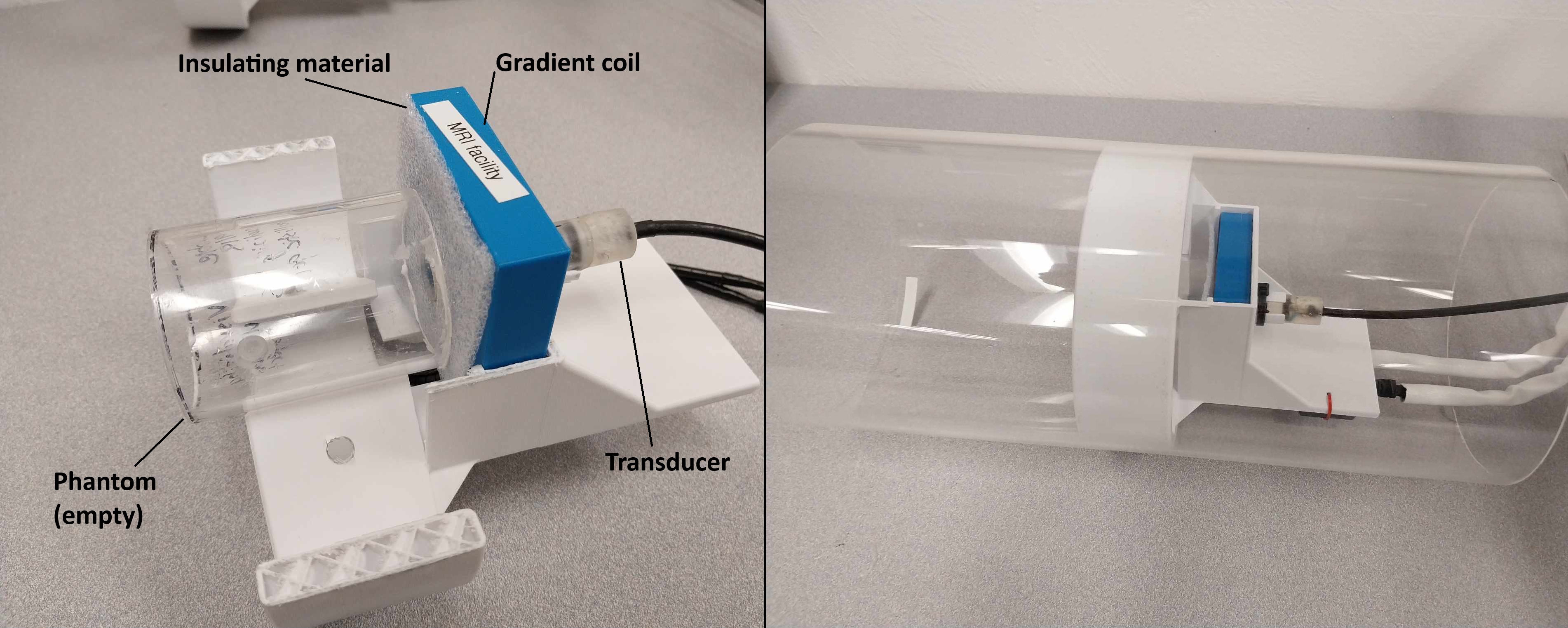
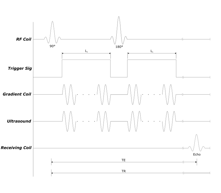
The transducer was acoustically coupled to a an agar gel phantom doped with chelated Gadolinium to shorten T1 relaxation through a gel interface. The final assembly, with the phantom, was placed inside of an acrylic pipe and wrapped in an 18 channel body coil, see Fig. 1. Prior to experimentation, a hydrophone (HNR Hydrophone, Onda Corporation, Sunnyvale, CA 94089) was used to measure peak pressure values within a sacrificial gel. Following the work of Plewes and Walker, the transducer and the gradient coil were both excited at the same frequency of 498.5 kHz. In synchrony with a spin echo sequence for a duration of 40 ms per TR, see Fig. 3. Peak current through the electromagnet was 25 A. MRI sequence parameters were: a Time to Echo (TE) of 60 ms, Time to Repeat of 500 ms (TR), Field of View (FOV) of 140 mm, and a resolution of 256x256 was used.
Acoustic pressure was calculated from the phase of the image using Eq 2. With ϕ being phase, ρ density, c speed of sound, γ the gyromagnetic ratio, ω the frenquency, and G0 the strength of the gradient.
$$Eq \space 2$$ $$$p(\phi)=\frac{2 \rho \omega c \phi}{\gamma G_0 T}$$$
Results
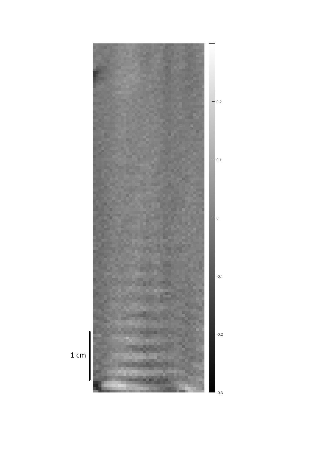
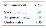
Figure 3 displays the complex phase of an acquired spin echo images acquired with and without acoustic propagation simultaneous to gradient coil excitation. Table 1 displays values of pressure estimated from both the acquired image, a hydrophone inserted into a sacrificial gel, and underwater. The data presents a discrepancy of 40 kPa between the sacrificial gel and the acquired image. The total peak current in the gradient coil was 25 ADiscussion
The acquired image had a relatively low contrast and poor discrepancy between the ultrasound and the background beyond 2 cm. There was a significant amount of noise present that could potentially be rendering the measured pressure to be deviant from it’s actual value. However, the measured pressure on the MRI fit in between the measured pressure of the transducer in water and the transducer coupled to the phantom. The background phase was not subtracted from the image. The gradient correction was not applied either. Background artifacts are present because of this. Some of these are likely caused by the phantom altering the electromagnetic field.Conclusions
The SNR of the ultrasound field can be improved by taking more images and averaging them together. This would lead to an SNR gain of √ N, with N being the number of acquisition. The depth of the measured field can be improved by using gradient coil with an extended magnetic field. The current pancake coil works fine for small measurements but it would prove to be inadequate for larger scale objects.Acknowledgements
This work was supported by the focused ultrasound foundation and NSF ERI 2138403.References
[1] D.B. Plewes, S. Silver, B. Starkoski, and C.L. Walker. Magnetic resonance imaging of ultrasound fields: Gradient characteristics. Journal of Magnetic Resonance Imaging, 11(4):452–457, 2000.
[2] C L Walker, F S Foster, and D B Plewes. Magnetic resonance imaging of ultrasonic fields. Ultrasound Med Biol, 24(1):137–142, January 1998.
Figures