4896
Bilateral Orthogonality Generating Acquisitions Method for Homogenous Balanced Steady-State Free Precession at 7T1UT Southwestern Medical Center, Dallas, TX, United States
Synopsis
Keywords: Parallel Transmit & Multiband, Brain, bSSFP, parallel transmission, transmit field inhomogeneity
Motivation: Elimination of the transmit field inhomogeneity effects in the brain for T2 contrast at 7T.
Goal(s): Removing the transmit field inhomogeneity effects in balanced steady state free precession acquisitions using Bilateral Orthogonality Generative Acquisitions method.
Approach: Bilateral Orthogonality Generative Acquisitions method is implemented at dual channel parallel transmit 7T system using several balanced steady state free precession acquisitions with varying scan parameters to eliminate the transmit field inhomogeneity effects and reduce the banding artifacts effects via different combining schemes in the final image.
Results: T2 contrast was obtained without the transmit field inhomogeneity effects but residual banding artifacts exists in the final images.
Impact: T2 contrast can be achieved without the transmit field inhomogeneity effects in the brain using balanced steady state free precession sequence.
Introduction
Balanced Steady State Precession (bSSFP) sequence has wide range of applications1-3 due to its versatility and fast acquisition. While it’s a gradient echo (GRE) acquisition, in bSSFP, T2 weighting can be achieved instead of T2*1-3. However, acquired images suffers from the banding artifacts due to the off-resonance effects1-3.In this work, Bilateral Orthogonality Generating Acquisitions (BOGA) method4, which was recently introduced to yield homogeneous T2* contrast in a dual channel parallel transmission (pTx) 7T system without need for B1+ calibration, is implemented with bSSFP for T2 contrast unaffected by the transmit field inhomogeneity. For reducing the effects of banding artifact, sum of squares and maximum intensity combining methods are implemented.
Theory
For a dual channel pTx system, the flip angle can be written as $$${\alpha}=(s_1+s_2)e^{i\mu_n}{\gamma}e^{i\delta}$$$5. $$$s_1$$$ and $$$s_2$$$ are the channel specific transmit sensitivities and $$$\mu_1$$$ and $$$\mu_2$$$ are the transmission phases of each channel. $$$\gamma$$$ denotes the magnitude of the complex flip angle, $$$\delta$$$ denotes the phase of the complex flip angle. Defining $$$q_n=s_ne^{i\mu_n}e^{i\delta}$$$ the flip angle expression for each channel can be simplified to $$${\alpha}_{1,2}=q_{1,2}\beta$$$.Using small flip angles, the bSSFP signal equation1,2 with low flip angle can be written as $$$S=\frac{{\rho}(1-e^{-TR/T_2}e^{-i\phi})e^{-TE/T_2}\alpha}{1+e^{-2TR/T_2}+2e^{-TR/T_2}cos(\phi)}$$$. Where $$$\rho$$$ is the proton density, $$$\phi$$$ is the phase accumulated due to the off-resonance effects, TR is the repetition time and TE is the echo time. Defining $$$A=\frac{{\rho}(1-e^{-TR/T_2}e^{-i\phi})}{1+e^{-2TR/T_2}+2e^{-TR/T_2}cos(\phi)}$$$, $$$S$$$ can be simplified as $$$S=Ae^{-TE/T_2}\alpha$$$.For the bSSFP implementation of the BOGA method, four input images are obtained with the same TR to fix the locations of the banding artifacts and effect of T2 decay in the magnitude of the steady state magnetization. Moreover, 2 sets of input images are obtained where the first set has no additional RF phase and second set has the additional RF phase of 180o to maximize the distance between banding artifacts between input sets for the reduction of the banding artifact mitigation methods. For both sets, input images are defined as $$$S_1=Ae^{-TE/T_2}(q_1+q_2)$$$ and $$$S_2=Ae^{-TE/T_2}(-q_1+q_2)$$$ and $$$S_{3,4}=Ae^{-TE/T_2}q_{3,4}$$$. By combining the four signals as in4, $$$C_1$$$ and $$$C_2$$$ can be defined as $$$C_1=S_3^*S_1+S_4S_2^*$$$ and $$$C_2=S_4^*S_1-S_3S_2^*$$$ . Final image is obtained as $$$I=\frac{\sqrt{0.5(C_1^*C_1+C_2^*C_2)}}{S_3^*S_3+S_4^*S_4}$$$4. Sum of squares and maximum intensity combination is implemented for the input images or the resulting images to determine the optimal order of image combination and BOGA method.
Methods
For the acquisition of the data, a 7T Philips Healthcare whole body human MRI system with two transmit channels is used along with a 32 channel receive Nova Medical head coil. For a healthy volunteer, the four above described bSSFP acquisitions were acquired each with voxel size of 1x1x1 mm, 256x256x192 acquisition matrix, TFE factor of 3800, compressed SENSE factor of 9 and 5o flip angle. TE1/TR = 12.3/25 ms and TE2/TR = 2.3/25 ms are used for first two and last two acquisitions. The final image has the effective echo time of 10 ms. For the second set of input images, 20 Hz offset is applied to generate the aforementioned RF phase difference of $$$\pi=2{\pi}f_{offset}TR$$$.Results
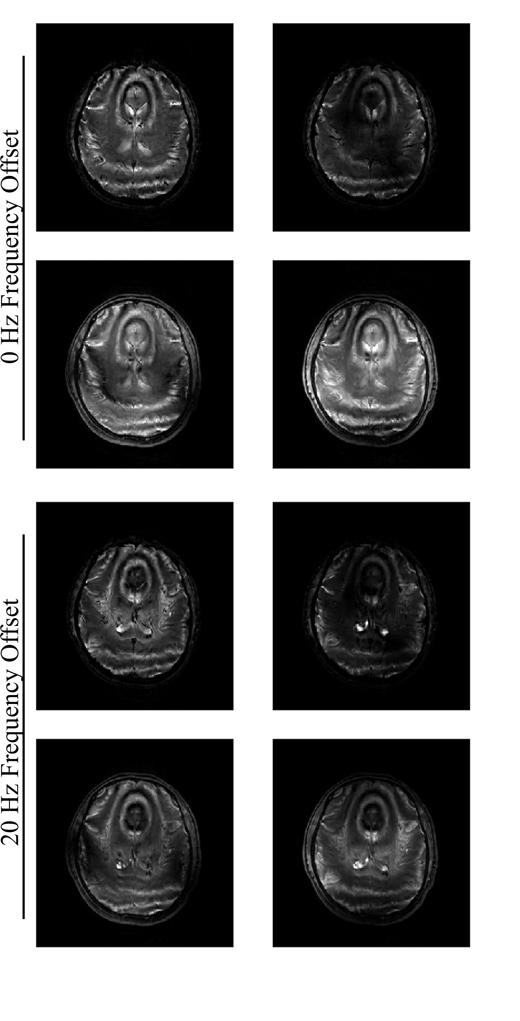
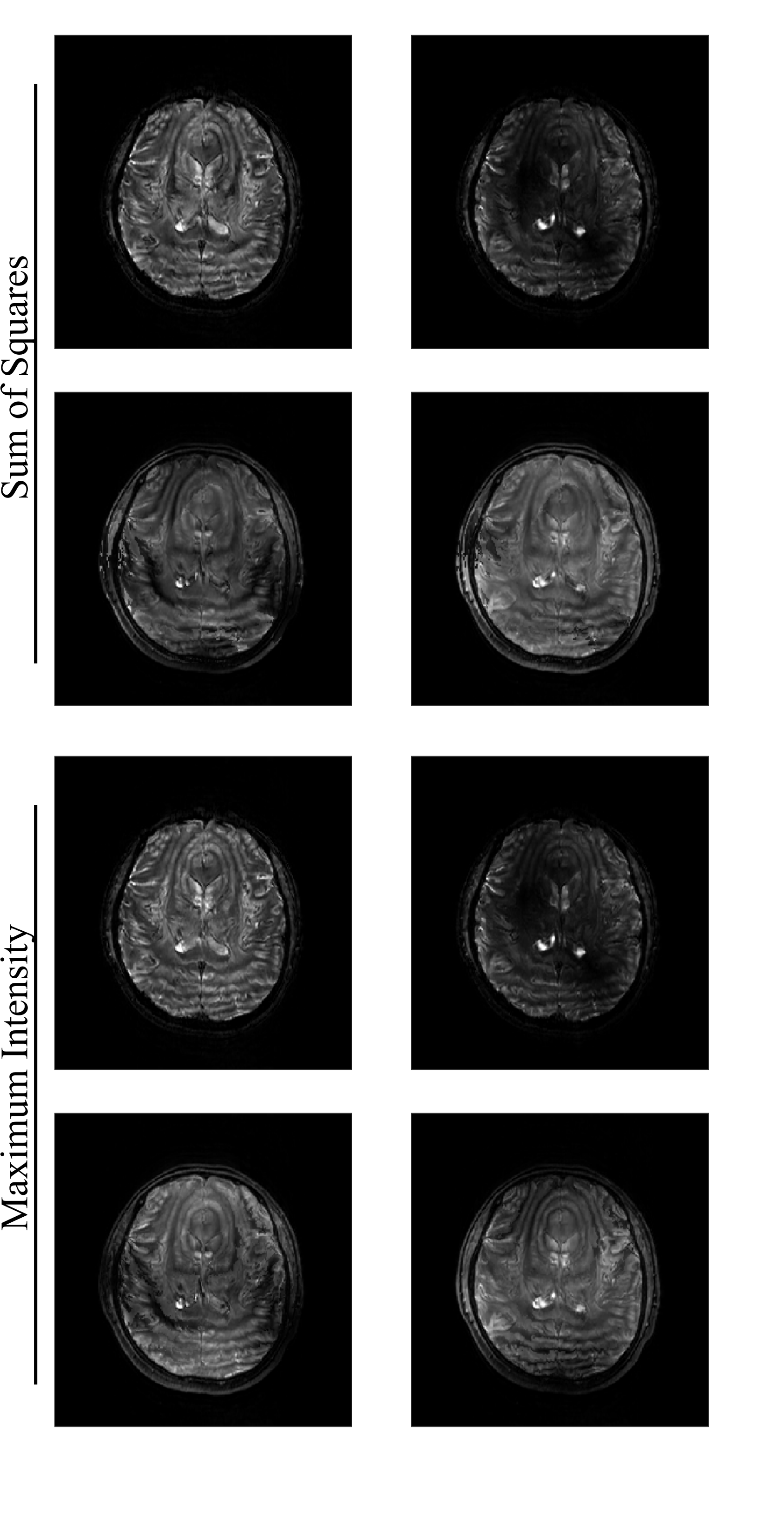
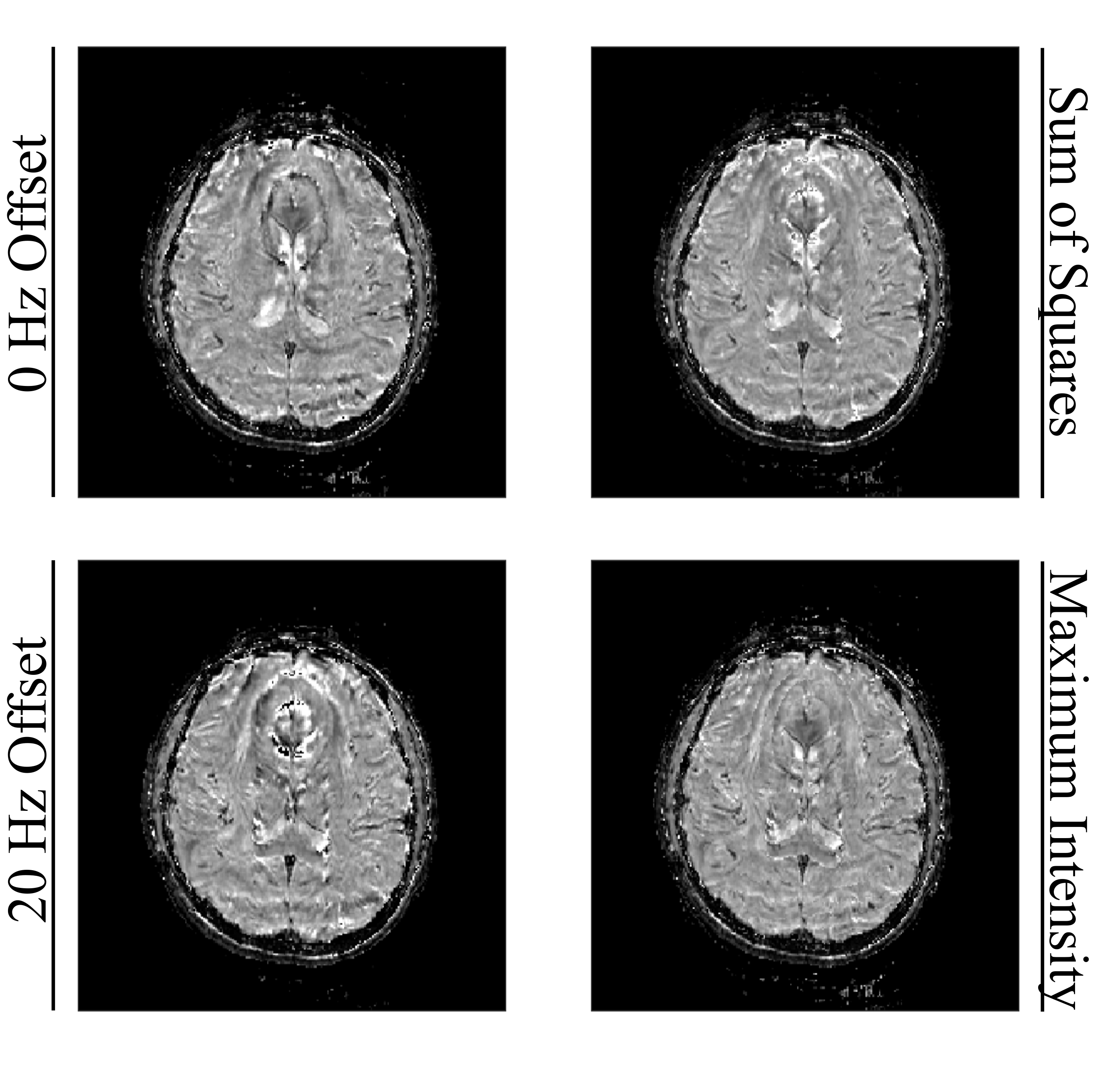
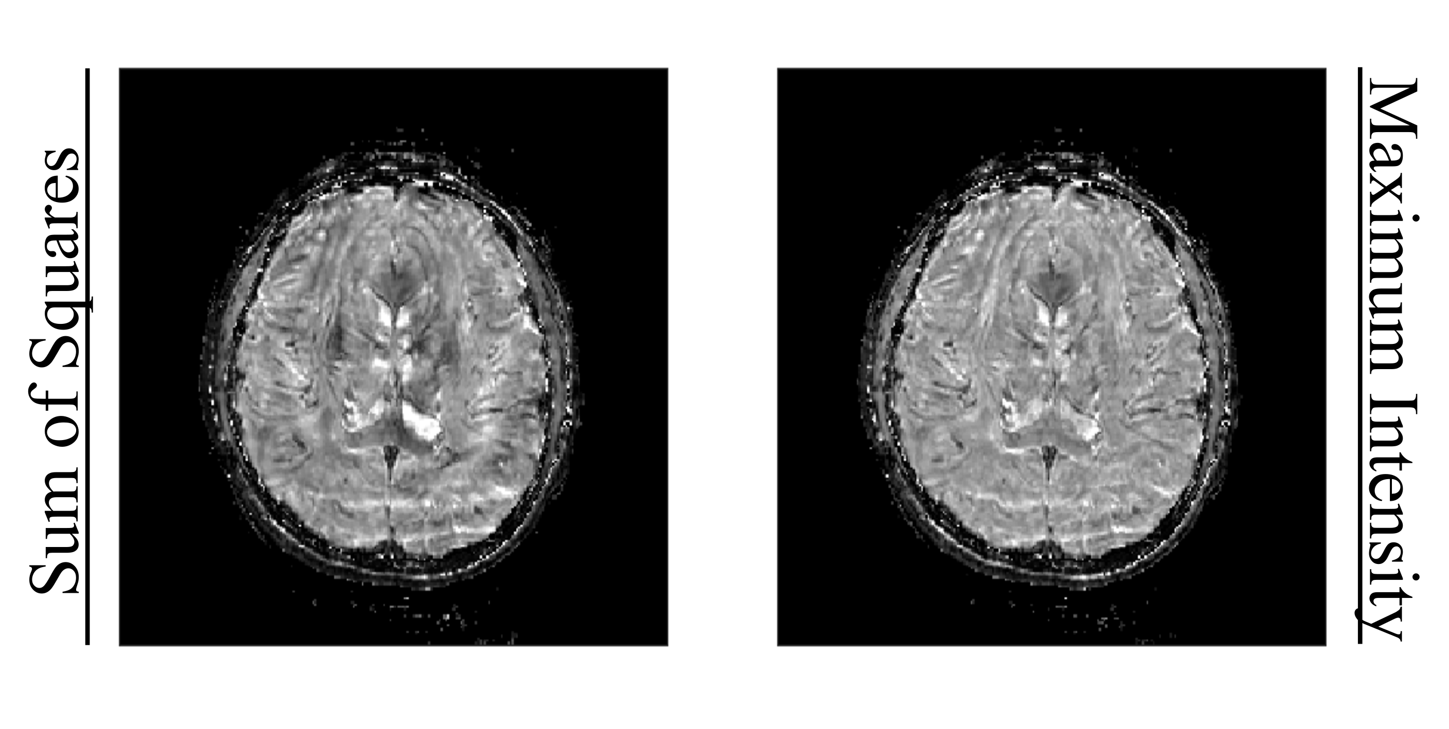
Figure 1 demonstrates the input images for the input sets with 0 and 20 Hz frequency offsets for the individual application of BOGA method. Figure 2 demonstrates the sum of square and maximum intensity combinations of the input images from Figure 1.Figure 3 illustrates the T2 images obtained via BOGA method using the input images demonstrated in the first column of the Figure 1. Second column demonstrates the sum of squares and maximum intensity combinations of images in the first column. Whereas Figure 4 shows the final transmit field inhomogeneity corrected T2 images obtained via BOGA method with combined input images.
All images obtained with this method are free of transmit field inhomogeneity effect, but images at the first column of the Figure 3 are significantly affected from the banding artifacts. While sum of squares and maximum intensity combinations reduce these affects, they do not completely eliminate it as can be seen in second column of the Figure 3 and Figure 4. Maximum intensity combination performs similarly when applied to input images or resulting T2 images. Whereas, sum of square combination performs worse when applied to the resulting images.
Discussion and Conclusion
In this work, T2 images without transmit field inhomogeneity effect are obtained using BOGA method with bSSFP acquisitions. Effect of the banding artifacts in the final images can be reduced using maximum intensity and sum of squares combinations but it cannot be fully eliminated. Future work includes implementation of banding artifact elimination method, instead of image combination, for obtaining homogeneous images without the banding artifact effects.Acknowledgements
This work was performed in the Advance Imaging Research Center at University of Texas Southwestern Medical center Dallas. This work was supported by Cancer Prevention and Research Institute of Texas (CPRIT) grant / RR180056.References
1. Scheffler K, Lehnhardt S. Principles and applications of balanced SSFP techniques. European Radiology. 2003;13(11):2409-2418. doi:https://doi.org/10.1007/s00330-003-1957-x
2. Bieri O, Scheffler K. Fundamentals of balanced steady state free precession MRI. Journal of Magnetic Resonance Imaging. 2013;38(1):2-11. doi:https://doi.org/10.1002/jmri.24163
3. Miller KL, Hargreaves BA, Lee J, Ress D, Christopher deCharms R, Pauly JM. Functional brain imaging using a blood oxygenation sensitive steady state. Magnetic Resonance in Medicine. 2003;50(4):675-683. doi:https://doi.org/10.1002/mrm.10602
4. Boga C and Henning A. “Bilateral Orthogonality Generating Acquisitions Method for Homogeneous T2* Images Using Dual Channel Parallel Transmission at 7T” In Proceedings of the 31st Annual Meeting of ISMRM, Toronto, Canada, 2023
5. Grissom W, Yip C-yu, Zhang Z, Stenger VA, Fessler JA, Noll DC. Spatial domain method for the design of RF pulses in multicoil parallel excitation. Magnetic Resonance in Medicine. 2006;56(3):620-629. doi:10.1002/mrm.20978
Figures