4783
Design of a new MRE transducer - placed between tissue and coil1High Field MR Center, Center for Medical Physics and Biomedical Engineering, Medical University of Vienna, Vienna, Austria, 2Center for Medical Physics and Biomedical Engineering, Medical University of Vienna, Vienna, Austria
Synopsis
Keywords: Elastography, Elastography, transducer, hardware, mre, elastography
Motivation: Design of a compact MRE transducer prototype that fits between patient and coil for direct stimulation of tissue.
Goal(s): The main goal of this study is to design and construct a new MRE transducer that can independently vary frequency and amplitude, is free of any magnetic parts and is suitable for cardiac MRE.
Approach: Using computer aided design (CAD) and different manufacturing processes, a functional transducer prototype was built that transforms pressurized air into gravitational force.
Results: A prototype that can induce tissue vibrations is presented. Its effectivity was verified by acceleration and phantom measurements.
Impact: The transducer induces waves whose amplitude and frequency can be selected independently. Its shape minimizes the distance between coil and patient for reducing MR signal losses with a comparatively large surface area for efficient wave transmission, optimized for cardiac MRE.
Introduction
Magnetic Resonance Elastography (MRE) is a method to assess tissue stiffness1. MRE is used to monitor changes in mechanical properties of the tissue to serve as indicator for diseases2. For instance, in cardiac MRE (cMRE), myocardial stiffness can be used as parameter to assess function of the heart3,4. Two major challenges in cMRE are positioning the transducer between patient and coil and producing enough actuation force to induce sufficient displacements in the heart. The greater the height of the transducer, the further the distance between the coil and the region of interest, resulting in lower MR signal. Transducer concepts with either flat design, variable masses5 or pneumatic actuation6 have been presented in the past, but none combine all these features into one compact design. This study introduces a newly designed pneumatically driven, gravitational transducer with a flat design to be placed between coil and patient.Materials and Methods
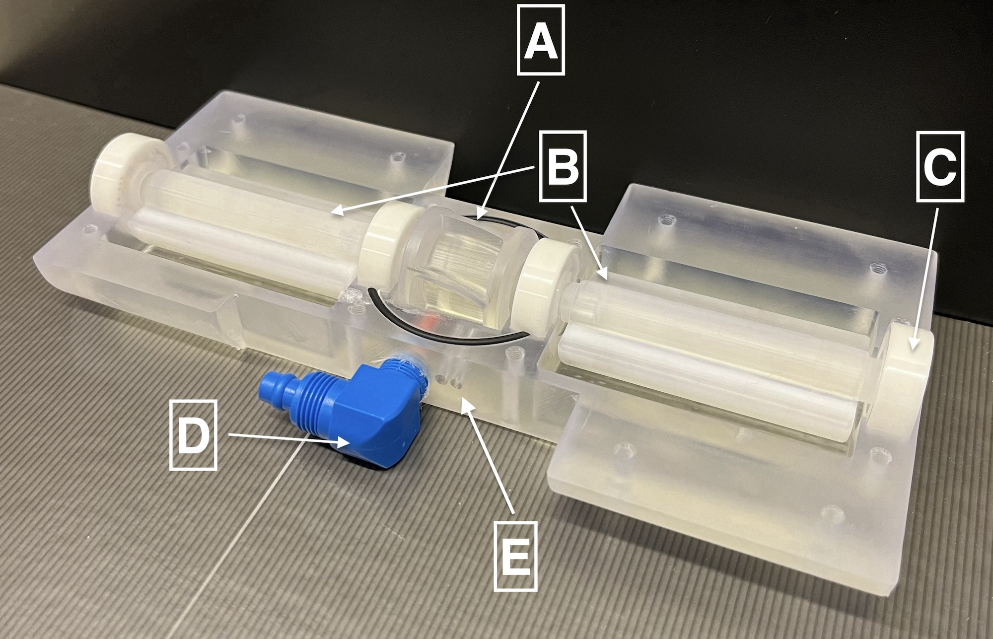
Transducer ConceptThe transducer uses compressed air to actuate a turbine centered between two unbalances, all stacked on one axis. Three slots in each of the unbalances can be filled with cylindrical Polytetrafluorethylene (PTFE) sticks to vary the mass and therefore the force output of the transducer, independently of the rotation speed. Unbalances and turbine are connected by a locking mechanism to ensure synchronous rotation of the whole stack. This modular block design of interchangeable parts allows for switching between various types of turbines and unbalances. The casing consists of a top and a bottom half, which are connected with nylon screws. Four ceramic (CrO2) bearings stabilize the rotating element of the transducer in its casing.
Turbine, unbalance and both case shells are CAD designed and printed using stereolithography (SLA) of a photopolymer resin. Two polyoxymethylene (POM) tube couplings are screwed into the case for compressed air inflow and exhaust, guiding the air away from the patient.
Control-Unit
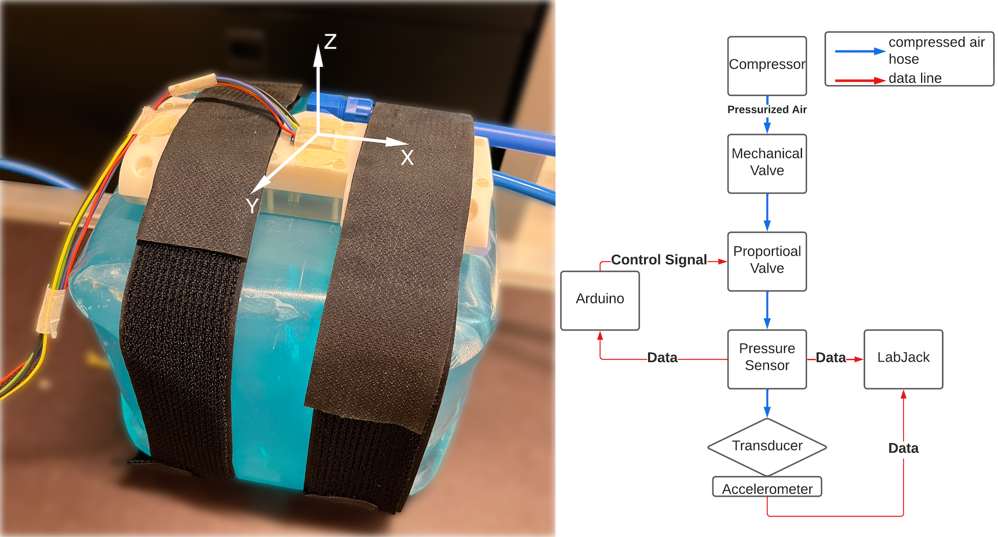
The control-unit consists of a proportional valve (Bürkert GmbH & Co. KG, Germany), a pressure sensor (Honeywell International Inc., USA), a microcontroller (Arduino S.r.l., Italy) and data acquisition box (DAQ) (Labjack Corporation, USA). The unit is triggered by TTL signals from the MR scanner. When activated, the microcontroller regulates the pressure in the system, keeping it at a constant level using a PID algorithm. This regulates the air pressure and thus the rotation frequency. The signal from the pressure sensor serves as setpoint for the controller. The pressurized air is supplied by a compressor (Adler Kompressoren GmbH, Austria) located in the equipment room next to the MR scanner, where also the control unit is located. Air tubes (15 m) connect the control unit and the transducer in the magnet bore.
The DAQ logs data for post processing. The control unit also consists of a fiber-optic sensor (SICK AG, Germany), which measures the rotation frequency of the transducer and can alternatively be used to control the transducer. The fibers are guided through the case towards the turbine (Figure 1).
Measurements
For performance evaluation, the transducer was strapped onto a cube (25x25x21cm) filled with ultrasound gel (Ultragel Medical Kft., Hungary) to measure the frequency and amplitude response. A 3-axis, ±3g accelerometer ADXL335 (Analog Devices, USA) was mounted on top of the transducer. Figure 2 shows the setup for the measurements.
Phantom and transducer were placed inside the MR scanner (3T PrismaFit, 4-channel flex Coil, Siemens). A synchronized MR sequence7 was used to measure shear waves inside the phantom. Sequence parameters: TE/TR: 7.38ms/60ms, matrix size: 64x64, FOV: 224x224mm, slice thickness: 3.5mm, vibration frequency: 40Hz, MRE gradient strength: 33mT/m.
Results
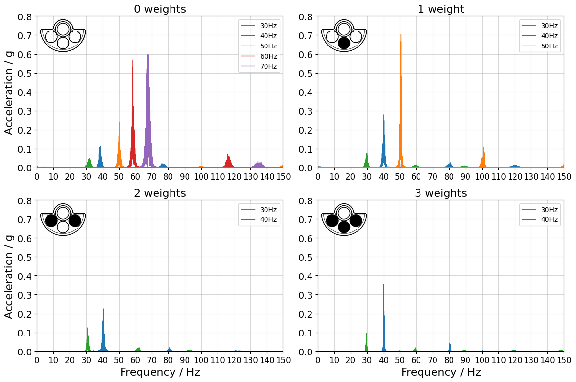
Acceleration data were measured with the DAQ for 2min at 1500Hz sampling frequency. Throughout the measurement, the pressure of the inlet tube was controlled using the pressure regulator.Figure 3 shows the frequency spectrum for several weight configurations at different rotation frequencies. The highest frequency was reached without any weights in the unbalances.
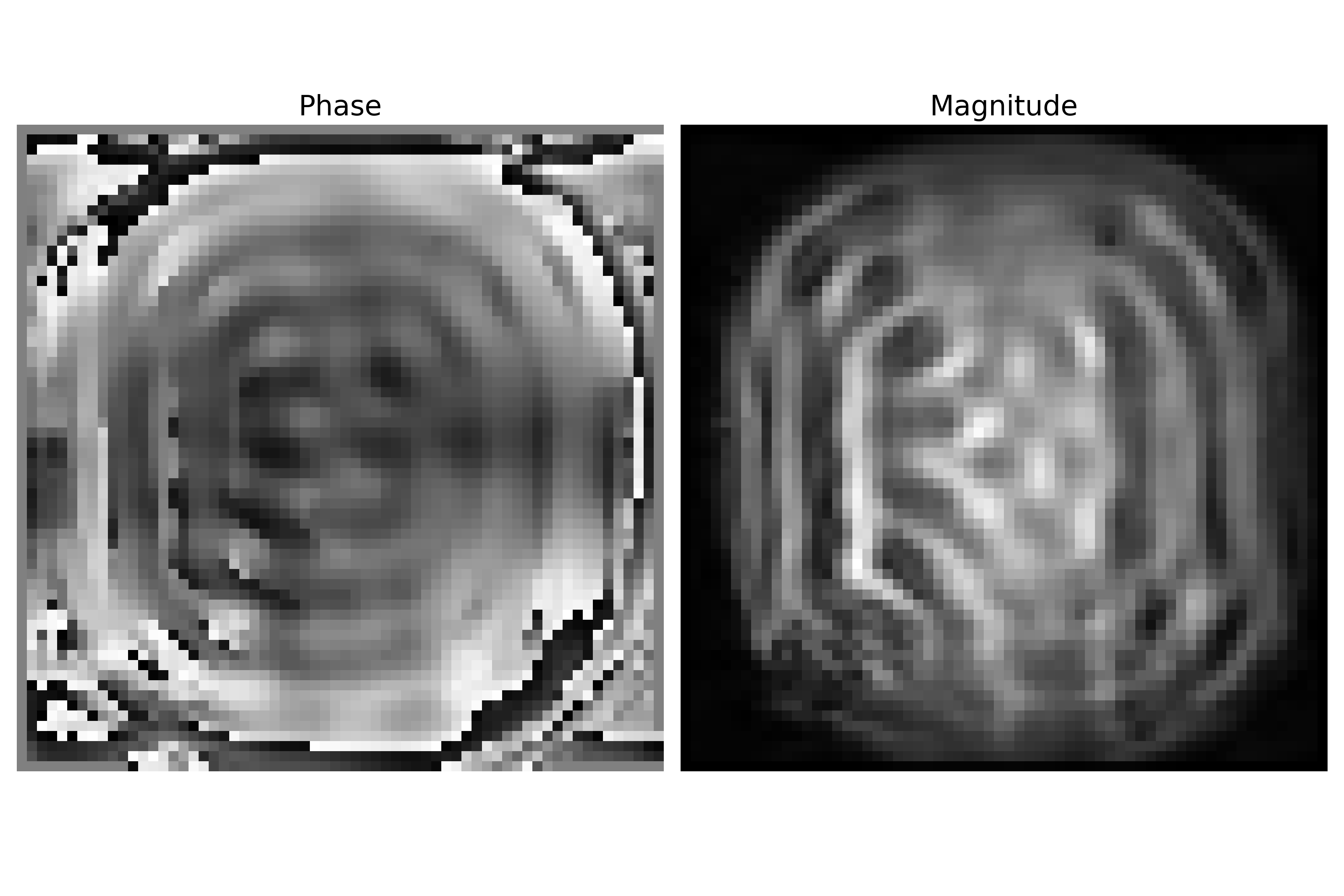
Magnitude and phase images from phantom measurements (sequence parameters describes above) in the MR scanner can be seen in Figure 4.
Discussion & Conclusion
This study presents a new pneumatically driven transducer with a flat design to limit distance between coil and patients as well as independently adjustable amplitudes and frequencies by changing either input pressure or weights. The setup was tested successfully in the MR environment. The vibration frequency and its amplitude can be varied by changing the pressure and exchangeable masses of the unbalance. Wave images were generated in a gel-phantom employing motion encoding gradients. Future work will focus on adapting the actuation turbine to reach higher rotation frequencies, improving the scanner-transducer synchronization as well as starting in-vivo scans.Acknowledgements
This study was supported by the Austrian Science Fund (FWF) projects P35607 and KLI 736-B30.
References
[1] R. Muthupillai, D. J. Lomas, P. J. Rossman, J. F. Greenleaf, A. Manduca, and R. L. Ehman, “Magnetic Resonance Elastography by Direct Visualization of Propagating Acoustic Strain Waves,” Science, vol. 269, no. 5232. American Association for the Advancement of Science (AAAS), pp. 1854–1857, Sep. 29, 1995. doi: 10.1126/science.7569924.
[2] Y. K. Mariappan, K. J. Glaser, and R. L. Ehman, “Magnetic resonance elastography: A review,” Clinical Anatomy, vol. 23, no. 5. Wiley, pp. 497–511, Jun. 03, 2010. doi: 10.1002/ca.21006.
[3] T. Elgeti et al., “Cardiac Magnetic Resonance Elastography,” Investigative Radiology, vol. 43, no. 11. Ovid Technologies (Wolters Kluwer Health), pp. 762–772, Nov. 2008. doi: 10.1097/rli.0b013e3181822085.
[4] S. Khan, F. Fakhouri, W. Majeed, and A. Kolipaka, “Cardiovascular magnetic resonance elastography: A review,” NMR in Biomedicine, vol. 31, no. 10. Wiley, Nov. 29, 2017. doi: 10.1002/nbm.3853.
[5] J. H. Runge et al., “A novel magnetic resonance elastography transducer concept based on a rotational eccentric mass: preliminary experiences with the gravitational transducer,” Physics in Medicine & Biology, vol. 64, no. 4. IOP Publishing, p. 045007, Feb. 06, 2019. doi: 10.1088/1361-6560/aaf9f8.
[6] W. Neumann et al., “A novel 3D printed mechanical actuator using centrifugal force for magnetic resonance elastography: Initial results in an anthropomorphic prostate phantom,” PLOS ONE, vol. 13, no. 10. Public Library of Science (PLoS), p. e0205442, Oct. 08, 2018. doi: 10.1371/journal.pone.0205442.
[7] O. I. Darwish et al., “Single Breath-Hold 3-Dimensional Magnetic Resonance Elastography Depicts Liver Fibrosis and Inflammation in Obese Patients,” Investigative Radiology, vol. 58, no. 6. Ovid Technologies (Wolters Kluwer Health), pp. 413–419, Jan. 21, 2023. doi: 10.1097/rli.0000000000000952.
Figures