4425
Accurate B0 field mapping using geometry in bSSFP imaging1Physics, University of Washington, Seattle, WA, United States, 2Radiology, University of British Columbia, Vancouver, BC, Canada, 3Radiology and Biomedical Imaging, University of California, San Francisco, San Francisco, CA, United States
Synopsis
Keywords: Quantitative Imaging, Quantitative Imaging, B0 static magnetic field mapping, bSSFP, ellipse, elliptical signal model
Motivation: High fidelity B0 field mapping is often desirable for corrections and contrast, although most methods available require addition image acquisitions.
Goal(s): To generate a robust B0 mapping approach that is quantitatively accurate, time-efficient, and allows further understanding of coil information.
Approach: The bSSFP geometric solution is leveraged to compute a B0 map from a novel off-resonance parameter calculation. The maps are validated via comparisons to standards and coil element-by-element phase images.
Results: Simulation, phantom, and in vivo data confirmed that the method for B0 mapping not only computes quantitatively-accurate field maps, but also permits estimation of other phase contributions including coil-specific phase offsets.
Impact: A robust B0 field mapping approach is proposed that facilitates research and clinical efforts seeking imaging techniques that minimize scan time and maximize practical data output.
Introduction
Magnetic field mapping is playing an increasingly important role in inhomogeneity artifact correction, system tuning/shimming, and phase-sensitive radiological applications. Previous work showed that using a four phase-cycled balanced steady state free precession (bSSFP) sequence, artifact-free images and magnetic field maps may be generated from the geometric solution (GS)1-3. However, field maps derived directly from the GS phase include global offset and coil-specific B1 phase contributions. These unwanted inputs contaminate accurate B0 quantification, inspiring a coil-element-by-element-consistent, quantitatively-accurate B0 mapping method. Here we demonstrate an approach that exploits bSSFP geometry to compute the off-resonance θ-angle map of the elliptical signal model (ESM), which is robust across multiple coil elements and combinatorially accurate, with immunity to other phase contributions.Methods
Theory:The bSSFP complex signal ESM is described in Eq.(1), with tissue and environment parameters $$$M_0,T_1,T_2,\alpha,TR$$$ grouped into the ESM parameters $$$M,a,b$$$:$$\begin{aligned}I(\theta,\psi)&=M\frac{1-ae^{i(\theta+\psi)}}{1-b\cos(\theta+\psi)}e^{-i\phi},\quad(1)\\E_1:&=\exp(-TR/T_1)\\E_2:&=\exp(-TR/T_2)\\a:&=E_2\\M:&=\frac{M_0(1-E_1)\sin\alpha}{1-E_1\cos\alpha-E_2^2(E_1-\cos\alpha)}\\b:&=\frac{E_2(1-E_1)(1+\cos\alpha)}{1-E_1\cos\alpha-E_2^2(E_1-\cos\alpha)}\end{aligned}$$
Here $$$\psi$$$ denotes the RF phase cycling increment, $$$\theta$$$ the B0-dependent off-resonant phase accumulation at TR, $$$\phi$$$ the off-resonant phase accumulation at TE that includes other phase contributions (RF phase offset $$$\phi_{\text{RF}}$$$, other phase offsets $$$\phi_{\text{drift}}$$$)4:$$\begin{aligned}\theta&=\gamma\Delta\,B_0\cdot\,TR,\quad(2)\\\phi&=\gamma\Delta\,B_0\cdot\,TE+\phi_{\text{RF}}+\phi_{\text{drift}}\end{aligned}$$
Arithmetic manipulation of signal $$$I_j=I(\theta,\psi_j)$$$ and the geometric cross-point M permits computation of $$$b,\theta$$$:$$\begin{aligned}b\cos\theta&=\frac{I_1+I_3-2Me^{i\phi}}{I_1-I_3}\\b\sin\theta&=\frac{I_2+I_4-2Me^{i\phi}}{I_4-I_2},\quad(3)\end{aligned}$$
Linearization of the GS (LGS)1 inspires solution regularization by minimizing the regional energy $$$E$$$ of weighted solutions $$$I_w$$$ from the cross-point M:$$E=\sum_{\text{region}}\left|I_w-Me^{i\phi}\right|^2,\quad(4)$$
where weighted solutions are formed from linear pairs of phase-cycled images $$$I_1,I_2,I_3,$$$ and $$$I_4$$$ via weights $$$w_{13},w_{24}$$$:$$\begin{aligned}I_{w13}&=I_1w_{13}+I_3(1-w_{13}),\\I_{w24}&=I_2w_{24}+I_4(1-w_{24}),\quad(5)\end{aligned}$$
$$$b,\theta$$$ can then be regularized based on their direct relations to these weights:$$b\cos\theta=1-2w_{13},\quad\,b\sin\theta=2w_{24}-1,\quad(6)$$
$$$\Delta\,B_0$$$ can then be solved from $$$\theta$$$ in Eq.(2) using phase unwrapping5.
Validation:
Four phase-cycled bSSFP images with $$$\psi=0^\circ,90^\circ,180^\circ,$$$ and $$$270^\circ$$$ respectively are generated for simulations and experimental MRI. Simulations employed $$$\alpha/TE/TR=30^\circ/5ms/10ms$$$, $$$T_2$$$ varied vertically from 10 to 150 ms, and $$$T_1$$$ (500 to 1500 ms) and $$$\theta\,\,(-4\pi\,\,\text{to}\,\,4\pi)$$$ varied horizontally. A spatially-varying phase offset and bivariate Gaussian noise at 2% of the mean signal intensity are added. Both $$$\theta$$$ and the LGS phase are unwrapped, $$$B_0$$$ maps computed pixel-wise, and the total relative error (TRE) evaluated6.
Experimental MRI involved scanning a water-grid phantom with a metal screw attached on a 0.55T Free.Max scanner and an in vivo sinus cavity on a 3T Vida scanner (Siemens Healthineers, Erlangen, Germany). bSSFP data employed $$$\alpha/TE/TR=70^\circ/3.8ms/7.5ms$$$ in 2D mode that required 8.8s/phantom slice, and $$$45^\circ/2.3ms/4.6ms$$$ in 3D mode that required 4.7s/in vivo slice. The multi-coil-element $$$\theta$$$ solutions are combined optimally either in complex format7, followed by phase unwrapping to yield a $$$B_0$$$ map.
An additional $$$B_0$$$ map was obtained for comparison using a dual-echo gradient echo (GRE) sequence acquired with $$$\alpha/TR/TE1/TE2=90^\circ/1090ms/5.2ms/18.1ms$$$ that required 11.6s/phantom slice, and $$$90^\circ/433ms/4.9ms/7.4ms$$$ that required 2.2s/in vivo slice.
Results
Figure 1 shows in simulations that the B0 map derived from Geometric θ accurately recovers the simulated B0 map, and can be subtracted from the LGS phase to recover the simulated phase offset.Figure 2 displays each of two coil element’s phantom bSSFP phase-cycled magnitude and phase images, along with the corresponding LGS phase and θ maps. The consistency of Geometric θ across different coil elements and the ability to reconstruct coil-element-specific phase offsets using the difference between LGS phase and Geometric θ is demonstrated.
Figures 3 and 4 demonstrate the consistency and accuracy of the B0 map generated from the Geometric θ solution when compared with the dual-echo GRE in phantom and in vivo data respectively, and that the LGS phase does not match the θ map or derived dual-echo field map due to other phase contributions.
Discussion
Simulation, phantom and in vivo images show that the field map induced by the Geometric θ solution is robust to other phase shift contributions and is consistent over all coil elements, in contrast to the LGS phase. This accurate estimation of the field map does not require additional image acquisition beyond the standard artifact-corrected LGS-bSSFP sequence or correction of phase shifts caused by non-B0-sources. It also allows easy extraction of coil-specific phase shifts via the difference between LGS phase and Geometric θ solutions, inspiring future enhancements in phase-preserved coil combination techniques.Conclusion
We propose a robust B0 field map approach based on bSSFP images that negates the need to obtain separate field maps. Its accuracy and coil-element-by-element consistency suggest its potential application in clinical use.Acknowledgements
No acknowledgement found.References
[1] Xiang Q-S, Hoff MN. Banding Artifact Removal for bSSFP Imaging with an Elliptical Signal Model. Magn Reson Med, 2014; 71(3):927:933, doi: 10.1002/mrm.25098.
[2] Hoff MN, Xiang Q-S. Correcting bSSFP Distortion near Metals with Geometric Solution Phase. In: Proc. ISMRM, Salt Lake City, USA, 2013. p. 2563.
[3] Taylor M, Valentine J, Whitaker S, Hoff MN, Bangerter N. “Field Mapping using bSSFP Elliptical Signal Model.” In: Proc. ISMRM, Hawaii, HI, USA, 2017. P. 3920.
[4] Shcherbakova, Y., van den Berg, C.A.T., Moonen, C.T.W. and Bartels, L.W. (2018), PLANET: An ellipse fitting approach for simultaneous T1 and T2 mapping using phase-cycled balanced steady-state free precession. Magn. Reson. Med, 79: 711-722.
[5] Miguel Arevallilo Herraez, David R. Burton, Michael J. Lalor, and Munther A. Gdeisat, “Fast two-dimensional phase-unwrapping algorithm based on sorting by reliability following a noncontinuous path”, Journal Applied Optics, Vol. 41, No. 35, pp. 7437, 2002.
[6] Chang Z, Xiang Q-S. Highly accelerated MRI by skipped phase encoding and edge deghosting with array coil enhancement (SPEEDACE). Med Phys 2006;33:3758.
[7] Xiang Q-S, Henkelman RM. Weighted Average and Its application in Ghost Artifact Reduction. In: 9th SMRI proceedings. ; 1991. p. 222.
Figures
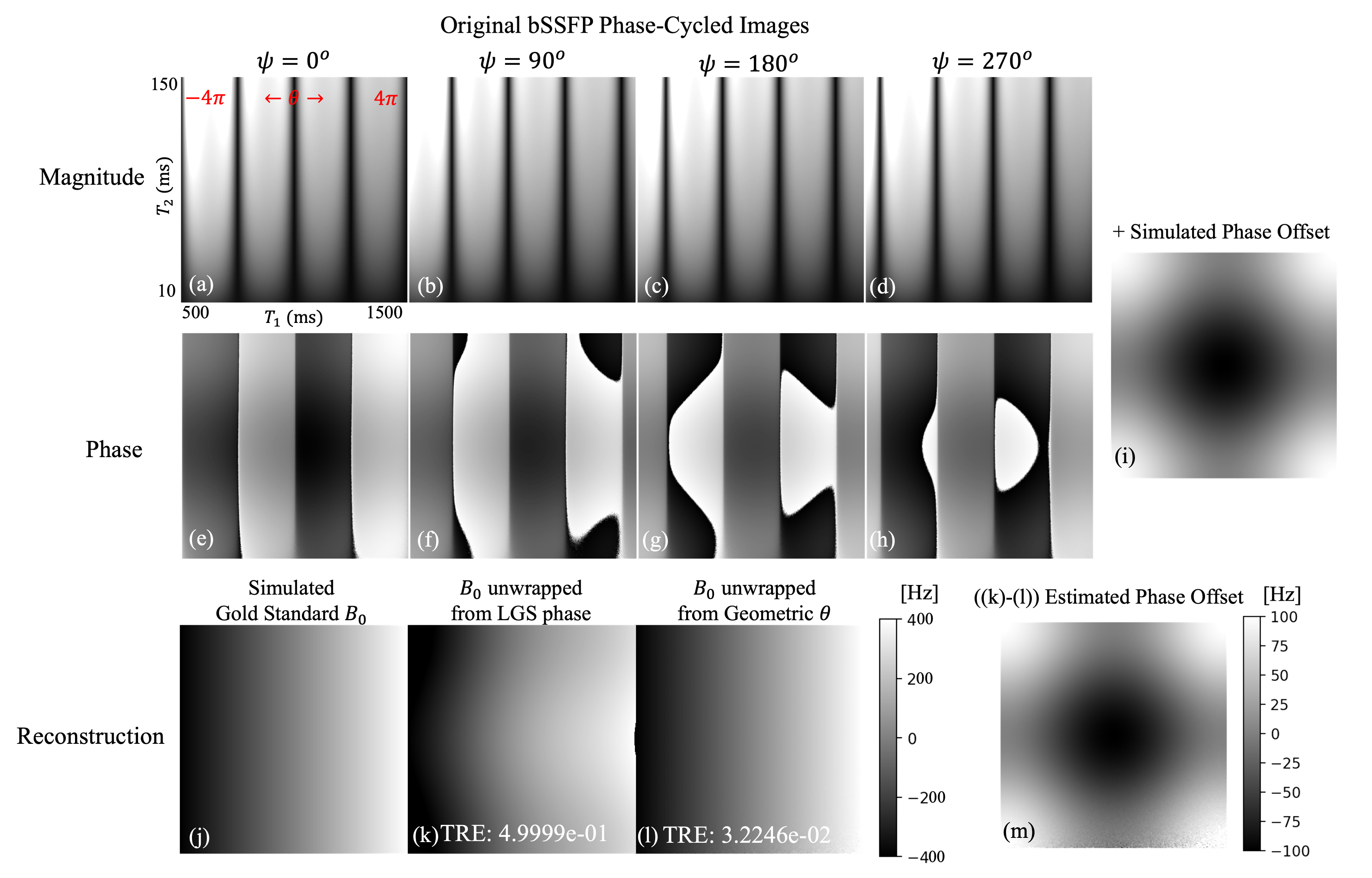
Figure 1: Simulated bSSFP (a-d) magnitude and (e-h) phase with $$$0^\circ,90^\circ,180^\circ,$$$ and $$$270^\circ$$$ phase cycling, 2% bivariate Gaussian noise added.
(i) Simulated phase offset is added to phase images.
B0 map (j) simulated (gold standard), (k) computed from unwrapped Linearized Geometric Solution (LGS) phase, and (l) computed from unwrapped Geometric θ, with total relative error computed for all pixels.
(m) The estimated phase offset based on the difference of the LGS phase and Geometric θ matches the simulated offset.
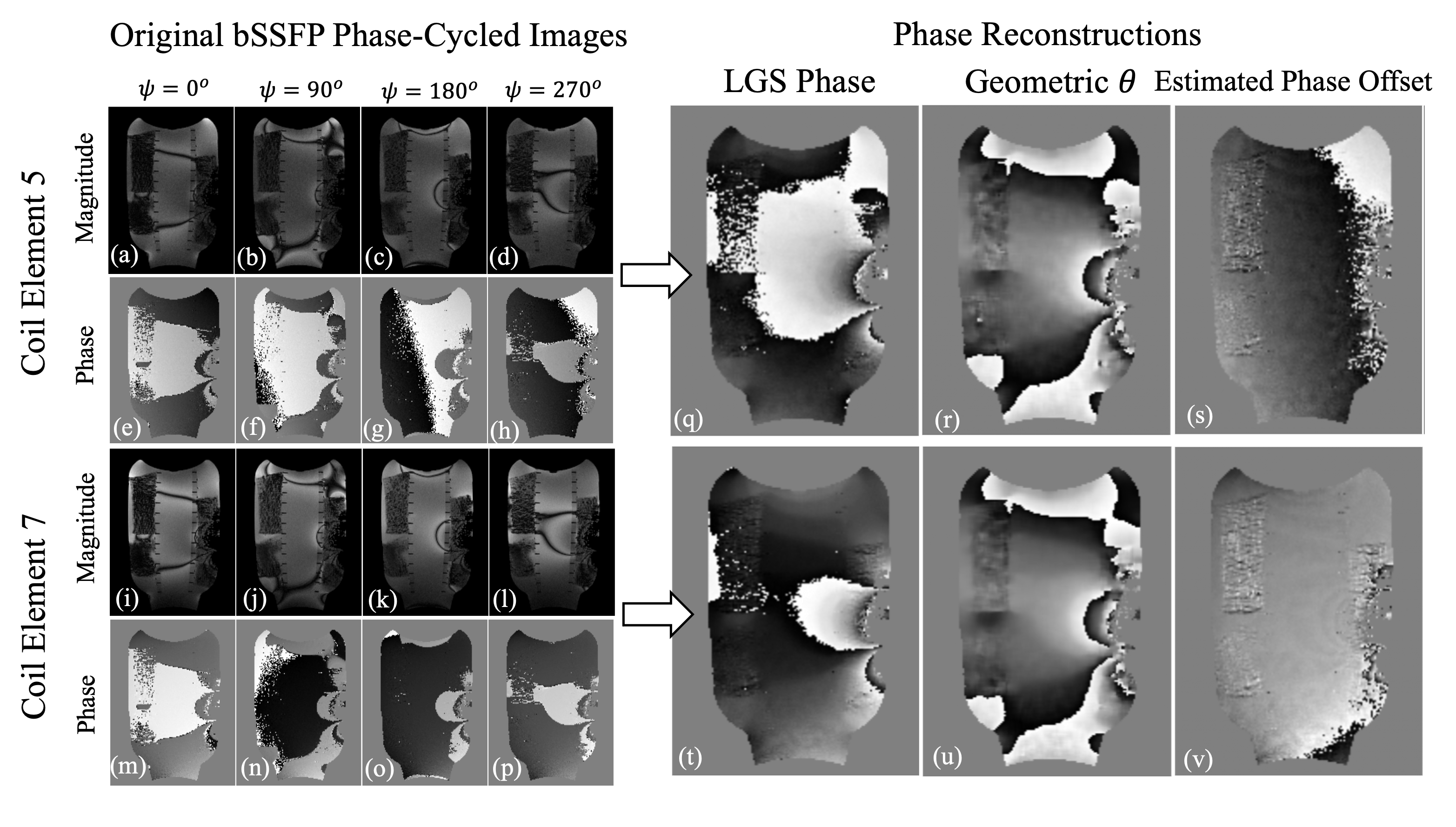
Figure 2: Water-grid-metal phantom 2D bSSFP MRI study depicting selected coil elements.
Element 5 (a-d) magnitude and (e-h) phase images and element 7 magnitude (i-l) and phase (m-p) images obtained at phase-cycled increments of $$$0^\circ,90^\circ,180^\circ,$$$ and $$$270^\circ$$$.
Linearized Geometric Solutions (LGS) phase for (q) element 5 and (t) element 7. Geometric θ solution for (r) element 5 and (u) element 7, and the estimated phase offset for (s) element 5 from the difference of (q) and (r), and for (v) element 7 from the difference of (t) and (u).
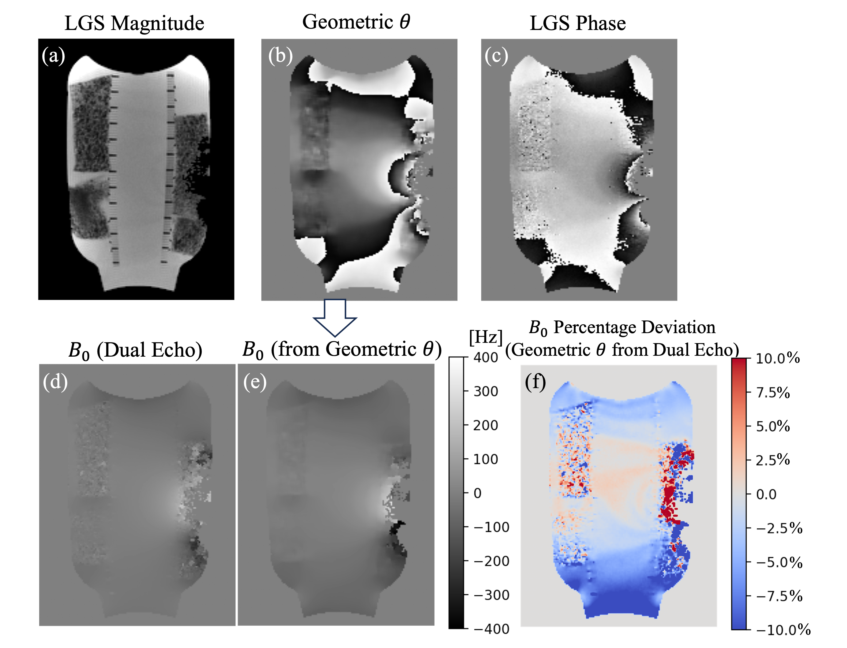
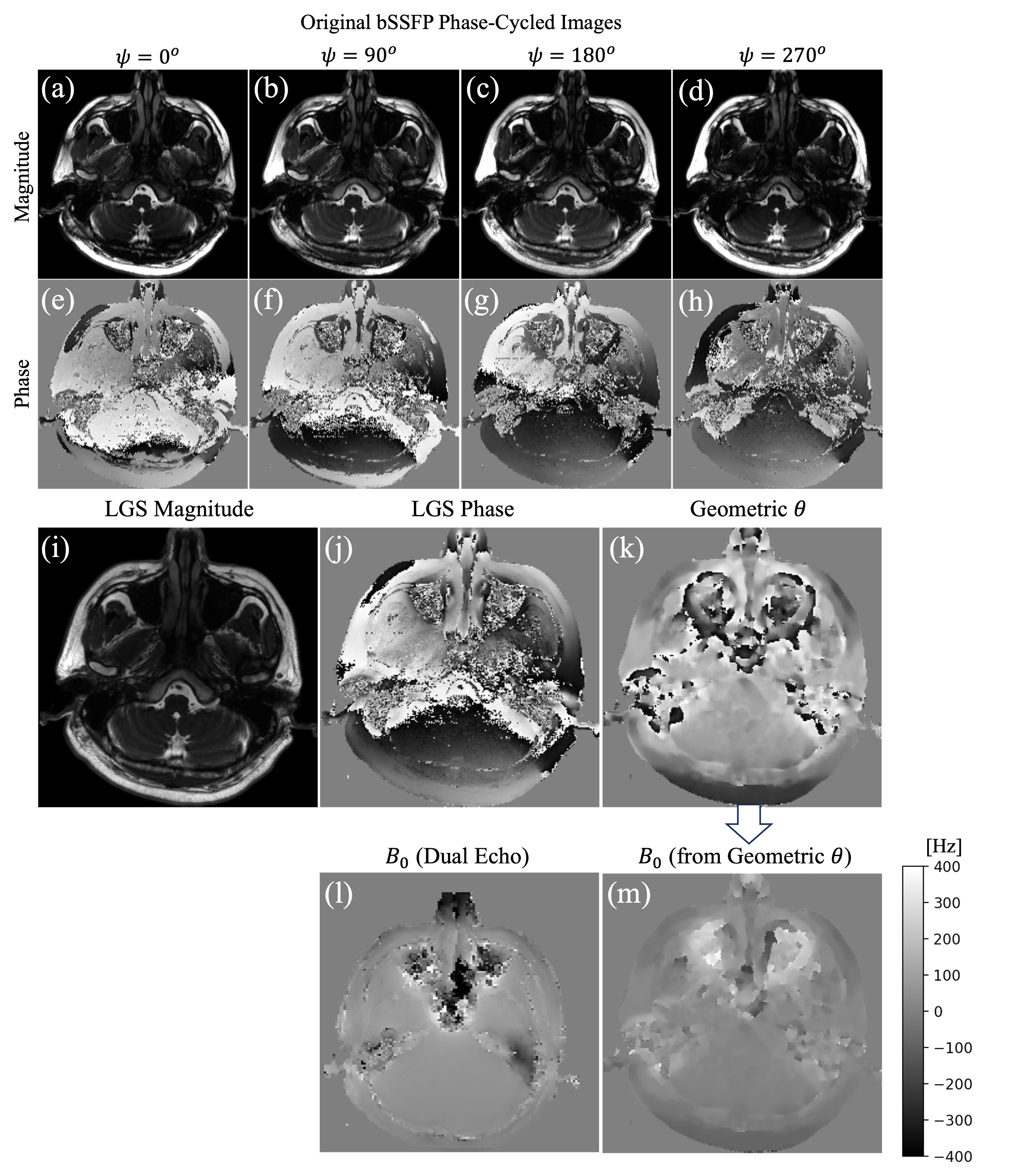
Figure 4: In vivo 3D bSSFP sinus cavity study with coil-combined data. (a-d) Magnitude and (e-h) phase images phase cycled at $$$0^\circ,90^\circ,180^\circ,$$$ and $$$270^\circ$$$.
LGS (i) magnitude and (j) phase, (k) Geometric θ solution, (l) dual-echo gradient sequence B0 map, and (m) B0 map derived from unwrapped Geometric θ solution in (k).