4095
Time-shifted multiband construction of wideband pulses1Wolfson Brain Imaging Centre, University of Cambridge, Cambridge, United Kingdom
Synopsis
Keywords: RF Pulse Design & Fields, RF Pulse Design & Fields
Motivation: Adiabatic pulses are popular for wideband inversion or refocusing, but limited by SAR in high-field. Conventional modulated pulses are limited in bandwidth by peak voltage requirements.
Goal(s): Develop an intuitive wideband pulse design method compatible with limited peak voltage for ultra-high field applications.
Approach: We construct a “multiband” pulse covering the desired bandwidth. We use time-shifting to reduce the peak voltage.
Results: We illustrate by designing a 4.4kHz bandwidth pulse, which has similar peak amplitude but better B1 robustness than a root-flipped SLR pulse. We use this pulse for semi-LASER MRS in a phantom, giving similar spectra to an adiabatic hypersecant pulse.
Impact: We introduce a time-shifted multiband method to design wideband pulses that is fast and intuitive to construct and avoids the tradeoff between RF peak amplitude and bandwidth. These pulses are useful for inversion or refocusing in twice-refocused sequences like semi-LASER.
Introduction
Ultra-high field (UHF) MRI improves signal-to-noise ratios (SNR) for imaging and spectroscopy. The increase in spectral bandwidth requires higher bandwidth pulses which are often limited by peak voltage.Adiabatic pulses are a popular response to these challenges.2 Offset-independent adiabatic (OIA) pulses generally require 20%-40% more energy than hard pulses or Shinnar Le-Roux (SLR)3 pulses.4 Often an upscaling factor is also applied to gain robustness to B1+ inhomogeneity at a cost of additional energy deposition.
With RF shimming helping to calibrate to desired B1+, optimized pulses (e.g. SLR) can deliver the required bandwidth without excessive energy deposition. However, the tradeoff between pulse length, bandwidth and peak voltage can make sequence optimization a challenging process. To achieve an acceptable peak amplitude of high bandwidth SLR pulses, root-flipping5 is required, which is time-consuming and sacrifices the frequency profile.
We introduce a multiband pulse design strategy for wideband (WB) pulses to avoid the trade-off between pulse bandwidth and peak amplitudes. Additionally, we apply time-shifting so that the frequency domain construction is fast and intuitive. Example pulses are validated with Bloch simulations and with semi-LASER6 phantom scans.
Theory
We start with a chosen subpulse with complex samples p(t), e.g. a sinc or SLR. We then construct a time-shifted multiband wideband pulse as follows::$$B_1(t)=\sum_{j=1}^{n_\mathrm{bands}}c_jp(t-\Delta t_j)\exp\left( i(\Delta f_jt+\phi_j)\right)$$
where each sub-band $$$j$$$ has a tunable frequency shift $$$\Delta f_j$$$, time shift $$$\Delta t_j$$$, amplitude $$$c_j$$$ and phase $$$\phi_j$$$ which we optimize.
Due to the non-linearity of Bloch equations, the magnetization responses of the subpulses are not additive, especially at large flip angles and when the bands are close in frequency (Figure 1). Hence in a previous study7 that proposed using sums of frequency bands to construct wide-band pulses, a pre-optimized frequency domain waveform was required.
However, if the subpulses are time-shifted, when their first zeros overlap (main lobes have no overlap), an approximately additive response is observed (Figure 2). Therefore, it is now possible to intuitively generate the desired bandwidth by summing waveforms of the constituent bands. Since the main lobes do not overlap in time, bandwidth can be increased by simply adding more bands without violating the peak amplitude constraint. It should be noted that the phase profile defined for a single subpulse is lost, which might provide a form of inbuilt RF spoiling for inversion pulses e.g. in ISIS8.
Methods
We demonstrate the WB construction with two example pulses:1. A 2.4kHz pulse with 3 SLR bands (“WB3”). One linear-phase spin-echo SLR pulse (TBW=6) was generated with SigPy,9 and scaled to 21µT peak B1+ and had 1kHz bandwidth. Three copies were placed 0.95 bandwidth apart in the frequency domain and time-shifted so that the central lobes were resolved at the first zero. Phases were matched at the passband edge between neighboring bands.
2. A 4.4kHz pulse with 5 SLR bands (“WB5”). The SLR subpulse was generated as above and inserted five times.
The amplitude, phase and frequency shift of each band were optimized simultaneously with the genetic algorithm optimizer in MATLAB, the cost function being $$$\sum_{n_\mathrm{freq}}(M_z+1)^2$$$ where $$$M_z$$$ is the longitudinal magnetization computed by Bloch simulation.
The B1+ and B0 dependency of the refocusing performance were computed with Bloch simulation for the WB5 pulse and HS4-R25 (5ms) and single SLR pulses with the same bandwidth. The effect of crusher gradients was simulated with 50 spatial locations, whose resulting magnetization were averaged.
Phantom validation was performed on a 7T Terra MRI (Siemens) and the BRAINO spectroscopy phantom (GE). Semi-LASER SVS was acquired with 135Hz water suppression for a 20 mm isotropic voxel, TE=47ms, TR=5000ms, and 4kHz bandwidth and either the WB5 pulse with RF shimming or a 5ms HS4-R25 refocusing pulse.
Results
Figure 3 shows the constructed wide-band pulses and their frequency response profiles. For WB5 with 4.4kHz passband bandwidth, the transition band is ~450 Hz, passband ripple <2.5%. The performance is comparable to a linear-phase SLR pulse with 4.8 kHz bandwidth and TBW=16.Figure 4 shows refocusing performance vs B1+ and B0. WB5 has a more regular range of acceptable B1+ than the root-flipped SLR pulse.
Figure 5 shows the simulated pulse performance in the ROI with RF shimming and experimental SVS spectra. Similar signals were obtained with the WB5 pulse and the reference HS4 adiabatic pulse. The WB5 pulse deposited 5.8J which is less than 8.9J for the HS4 pulse.
Dicussion and Conclusions
Time-shifted multiband construction yields wideband pulses with low peak amplitude requirements. It offers intuitive control over the desired frequency response and is fast to optimize. We demonstrate its use for semi-LASER SVS in a phantom.Acknowledgements
This research was supported by the NIHR Cambridge Biomedical Research Centre (BRC-1215-20014). The views expressed are those of the author(s) and not necessarily those of the NIHR or the Department of Health and Social Care. The Cambridge 7T MRI facility was co-funded by the University of Cambridge and the Medical Research Council (MR/M008983/1). M.Z. is supported by the Medical Research Council (MR N013433-1) and the Cambridge Trust. C.T.R. acknowledges research support from Siemens. M.Z. thanks Carina Graf for helpful discussions.
References
1. Uğurbil, K. Imaging at ultrahigh magnetic fields: History, challenges, and solutions. NeuroImage 168, 7–32 (2018).
2. Tannús, A. & Garwood, M. Adiabatic pulses. NMR in Biomedicine 10, 423–434 (1997).
3. Pauly, J., Le Roux, P., Nishimura, D. & Macovski, A. Parameter relations for the Shinnar-Le Roux selective excitation pulse design algorithm (NMR imaging). IEEE Transactions on Medical Imaging 10, 53–65 (1991).
4. Garwood, M. & DelaBarre, L. The Return of the Frequency Sweep: Designing Adiabatic Pulses for Contemporary NMR. Journal of Magnetic Resonance 153, 155–177 (2001).
5. Shinnar, M. Reduced power selective excitation radio frequency pulses. Magnetic Resonance in Medicine 32, 658–660 (1994).
6. Scheenen, T. W. J., Heerschap, A. & Klomp, D. W. J. Towards 1H-MRSI of the human brain at 7T with slice-selective adiabatic refocusing pulses. Magn Reson Mater Phy 21, 95 (2008).
7. Starčuk, Z., Půček, L. & Starčuk, Z. New symmetric frequency-selective RF pulses for population inversion. Journal of Magnetic Resonance (1969) 80, 352–358 (1988).
8. Ordidge, R. J., Connelly, A. & Lohman, J. A. B. Image-selected in Vivo spectroscopy (ISIS). A new technique for spatially selective nmr spectroscopy. Journal of Magnetic Resonance 66, 283–294 (1986).
9. Martin, J. B. et al. SigPy.RF: Comprehensive Open-Source RF Pulse Design Tools for Reproducible Research. in Proc. Intl. Soc. Mag. Reson. Med. vol. 28 1045 (2020).
Figures
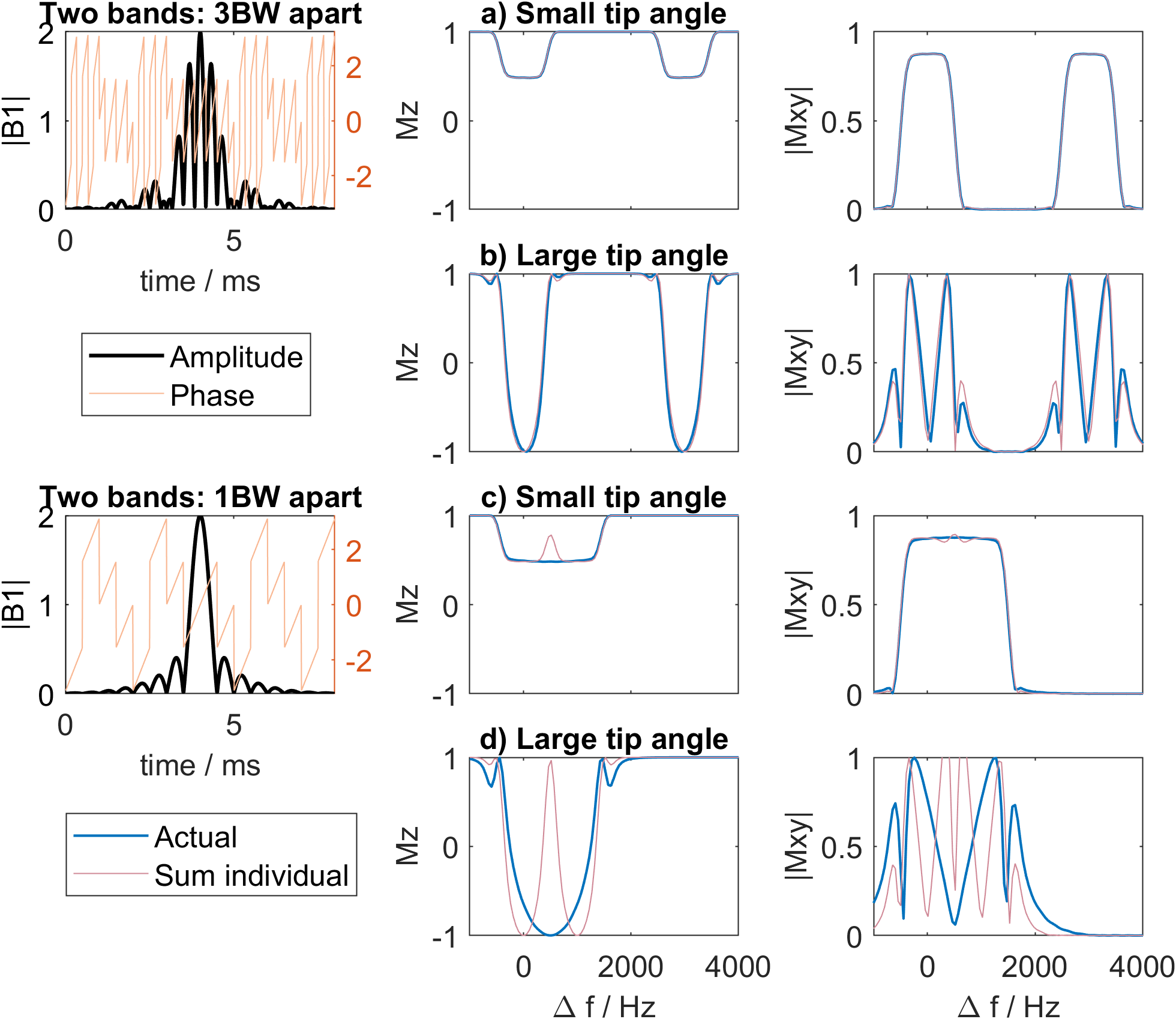
Figure 1 Comparison between the actual frequency response for a 2-band sinc pulse and the sum of that of the two individual bands. The example sinc has bandwidth 1000Hz. (a-b) The two bands are spaced at 0Hz and +3000Hz and in (c-d) 0Hz and +1000Hz. When the two bands of a multiband pulse are spaced (in frequency) closer than approximately one bandwidth apart, the frequency response deviates significantly from the sum of frequency bands of individual pulses especially at large tip angles.
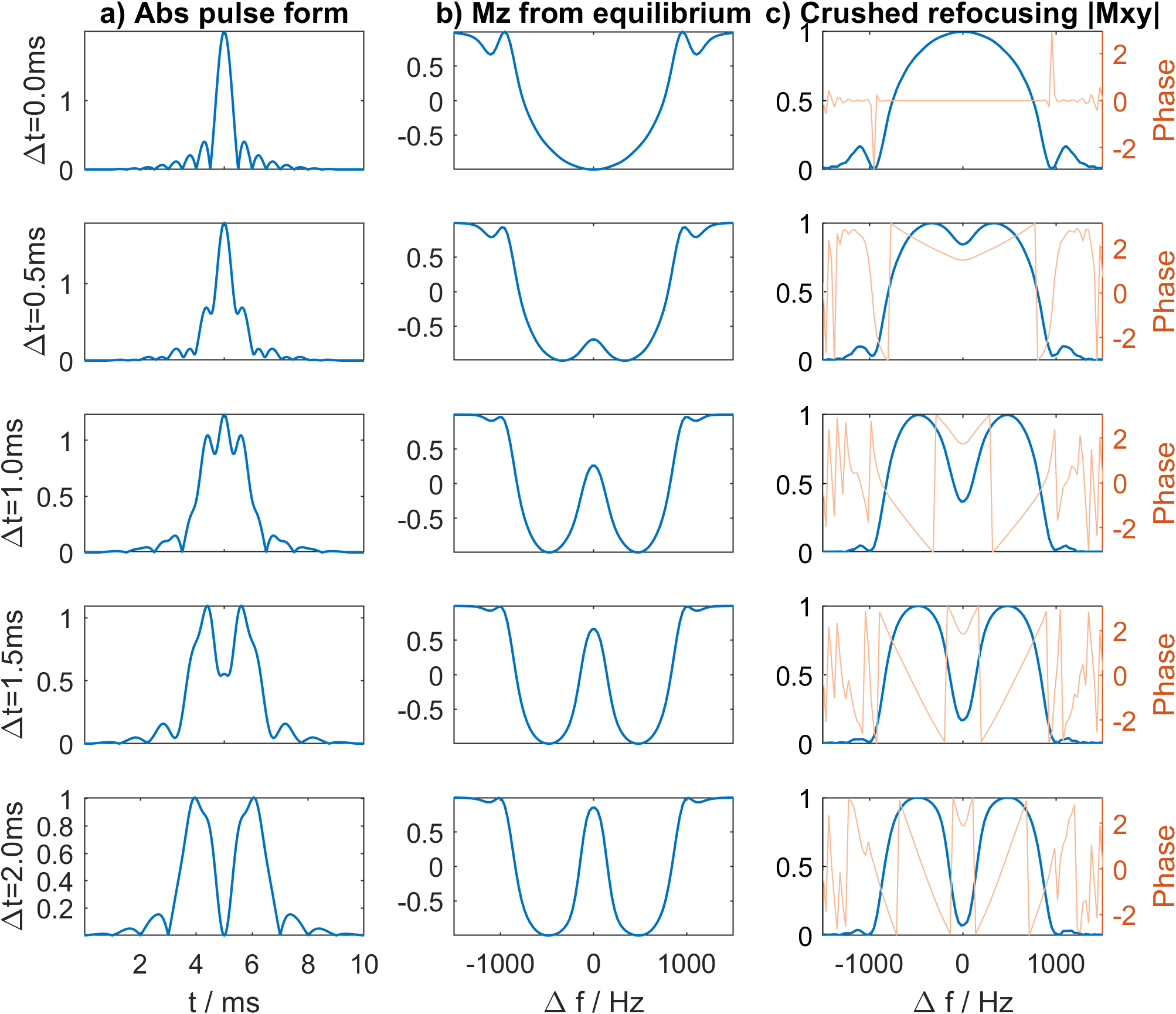
Figure 2 The effect of time-shifts on the frequency response of the 2-band 180° sinc pulse with 1000Hz bandwidth, placed at -500Hz and +500Hz. Time shifting a multiband pulse with close frequency spacing can gradually restore the sum of frequency bands of individual pulses. The full restoration (last row, cf. Figure 1 d) happens when the main lobes of the two pulses are resolved in time domain. Column b) is computed with Bloch simulation from Mz=1, and column c) is computed starting with Mx=1 with the effect of crusher gradients on both sides of the pulse simulated with 50 spatial locations.
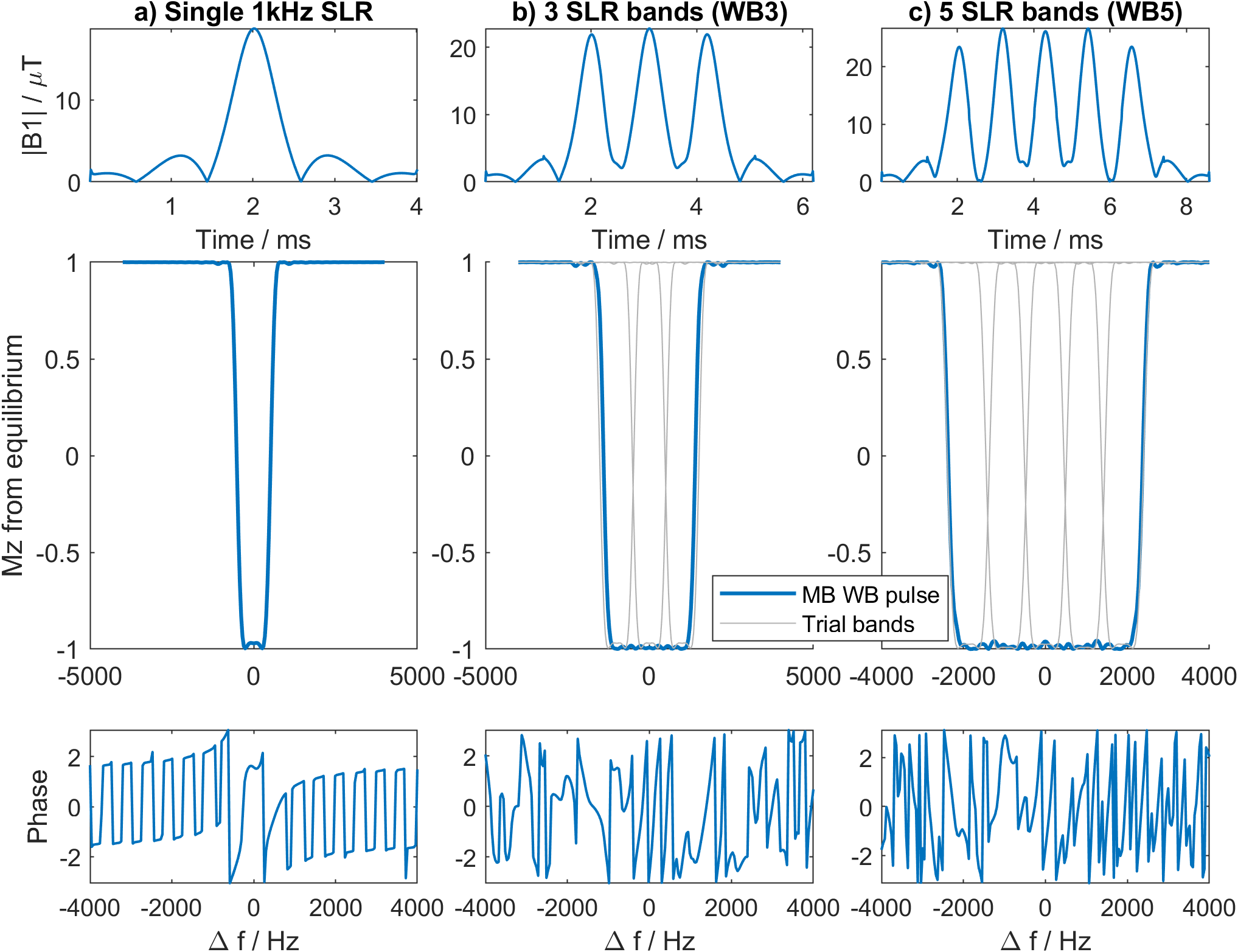
Figure 3 The form, frequency response and phase of (a) a single SLR pulse with 1kHz bandwidth, (b) time-shifted wideband pulse (passband 2.4kHz) consisting of 3 SLR pulse bands and in (c) 5 SLR bands (passband 4.4kHz). The grey lines outline the individual frequency bands used to construct the wide band pulses. The WB5 pulse achieves a passband bandwidth of 4.4 kHz, comparable to a single SLR pulse with 4.8kHz bandwidth and TBW=16.
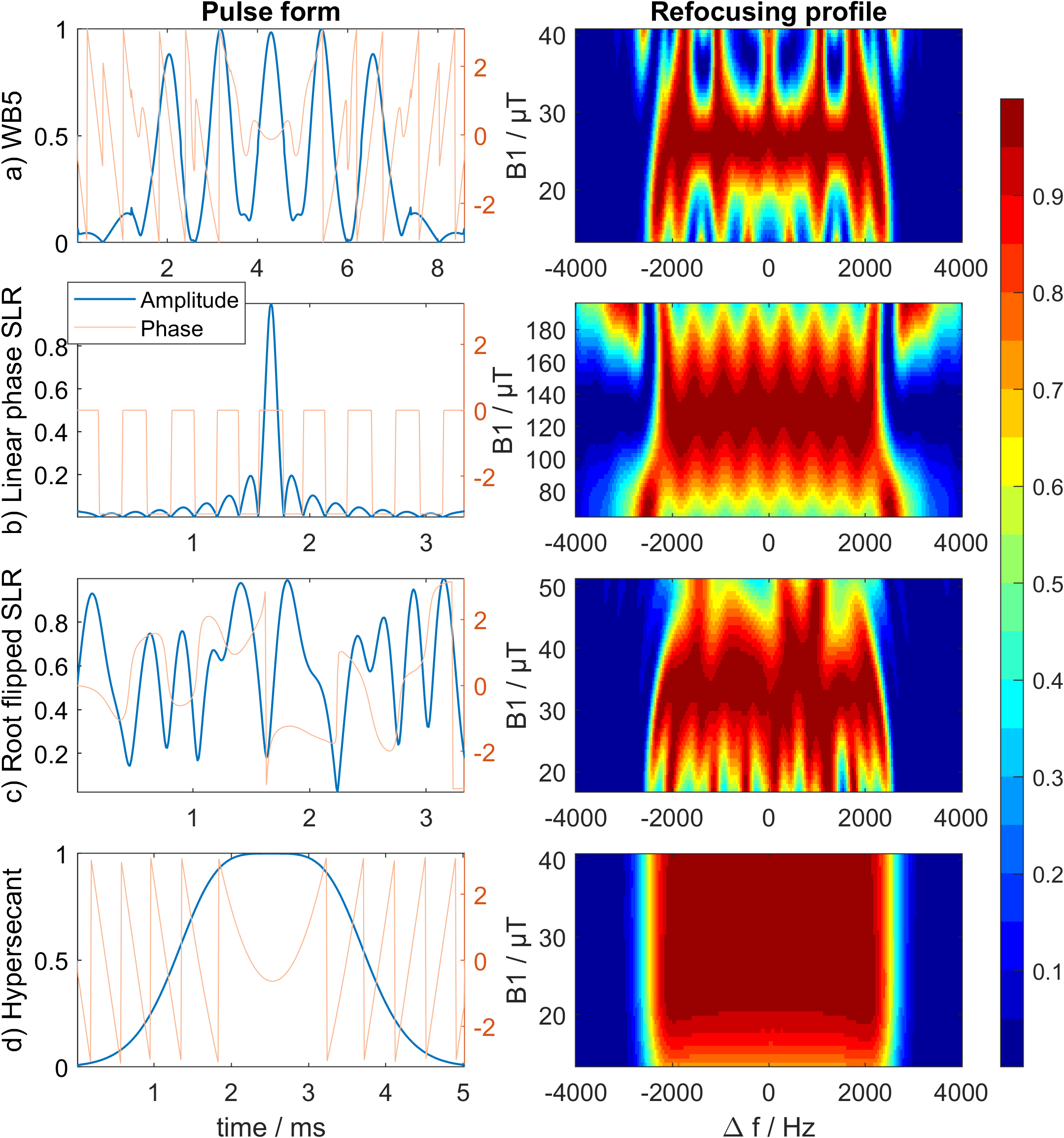
Figure 4 The pulse form and simulated refocusing performance comparison between a) our time-shifted WB5 pulse, b) a single linear phase SLR pulse with matching bandwidth and transition band, c) the corresponding root-flipped SLR pulse with minimum peak amplitude, and d) the 5ms HS4-R25 adiabatic pulse. The WB5 shows a more regular region (rectangular) of acceptable B1 values than the root flipped SLR pulse.
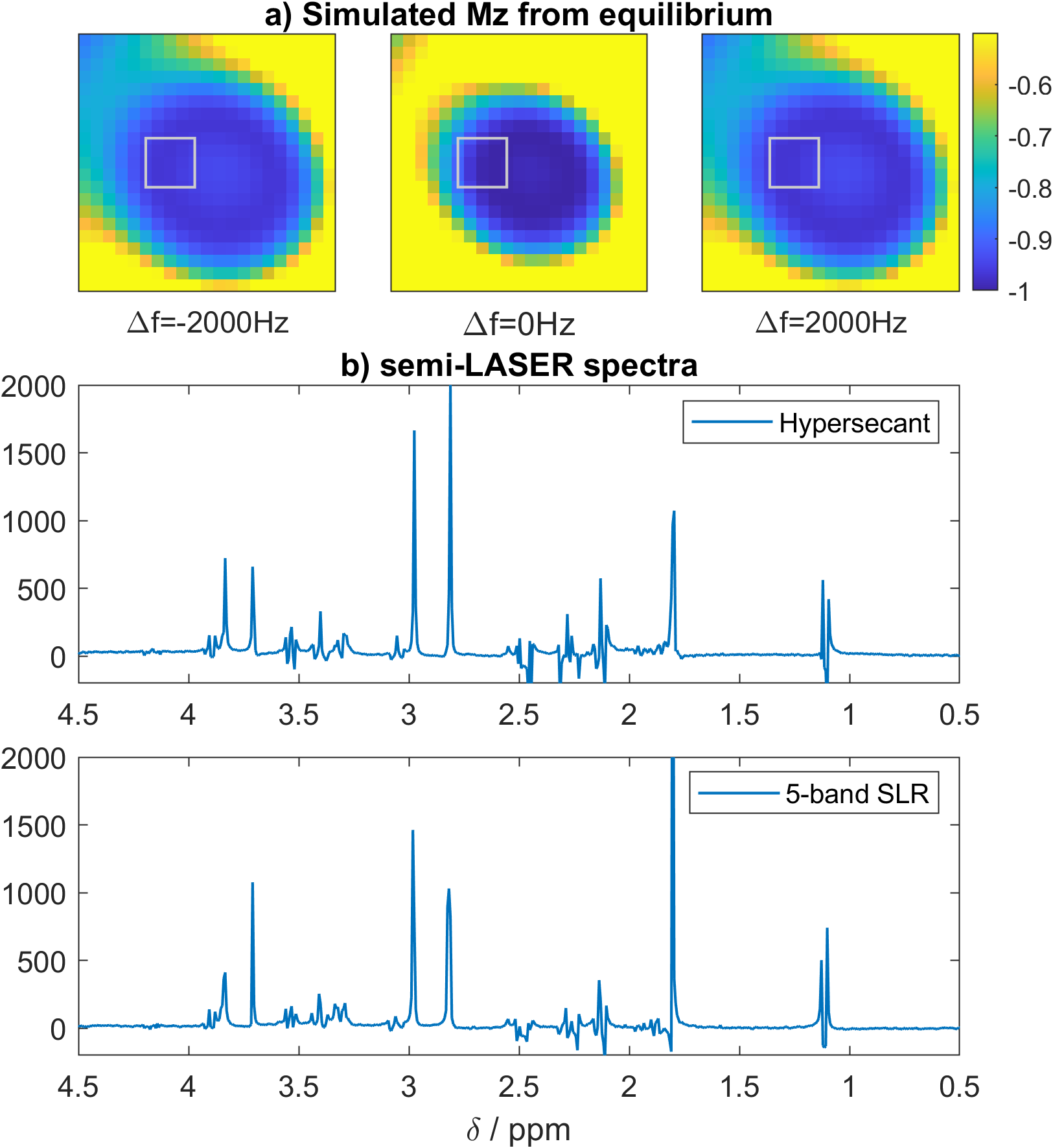
Figure 5 a) The simulated Mz from equilibrium inside an aqueous phantom, with the WB5 pulse in Figure 3, at water frequency and 2000Hz off resonance, after RF shimming. FOV 100x100mm2, voxel size 20x20mm2. b) Comparison of the semi-LASER spectra acquired with TE=47ms in the voxel highlighted in a), with the WB5 pulse and a 5ms HS4-R25 adiabatic pulse with matching passband bandwidth.