4087
Mitigation of radiated E-field from a 3T MRI system operated without a Faraday shielded room using parallel transmission1A. A. Martinos Center for Biomedical Imaging, Department of Radiology, Massachusetts General Hospital, Charlestown, MA, United States, 2Harvard Medical School, Boston, MA, United States, 3Harvard-MIT Division of Health Sciences Technology, Cambridge, MA, United States
Synopsis
Keywords: RF Arrays & Systems, RF Arrays & Systems, Transmit radiation, Birdcage coil, Faraday cage
Motivation: Eliminating the Faraday cage would lower installation costs by ~2X and facilitate deployment of MRI in diverse settings, but requires reducing the Tx system’s electromagnetic (EM) radiation.
Goal(s): We employ a parallel transmit (pTx) array and EM absorbers to reduce RF-radiation from a 3T MRI operating without a shielded room, ensuring operation within regulatory limits.
Approach: We model a 3T MRI with a CP body coil and design a 16-channel pTx array and EM-absorber to reduce E-field radiation. Performance is assessed with pTx pulse optimization and L-curve analysis.
Results: We demonstrate a 2270-fold reduction in radiation compared to the birdcage coil.
Impact: By successfully mitigating RF-radiation from MRI systems operated without Faraday cages, this research advances cost-effective MRI installations in diverse clinical/research environments, encouraging further exploration of pTx technology for controlling electromagnetic fields both inside/outside of the body.
Introduction
Eliminating the traditional RF-shielded cabin (Faraday cage) in clinical MRI could reduce installation costs and simplify placement in diverse settings. The Faraday cage mitigates two key issues: the receive problem, where incoming electromagnetic (EM) interference increases image noise and artifact levels1-7, and the transmit problem, whereby EM radiation exiting the scanner’s body Tx coil might interfere with hospital equipment8. To address the Tx problem, regulatory limits9,10 (IEC-60601-1-2 & CISPR-11) limit peak E-field on a 10-m radius sphere (peak-E10m) to below 1-mV/m during 3T MRI. Our previous modeling of EM radiation from conventional field-strength, body-loaded superconducting scanner geometries without a Faraday room demonstrated radiation levels significantly above this regulatory threshold11. Without some replacement mitigation method, MRI radiation limits would severely limit Tx operation. In this study, we use EM simulations of far-field E-field levels (peak-E10m) and patterns for a 3T scanner with a conventional CP birdcage body coil to propose and examine an active and passive mitigation strategy employing parallel transmit (pTx) array coil pulse optimization.Methods
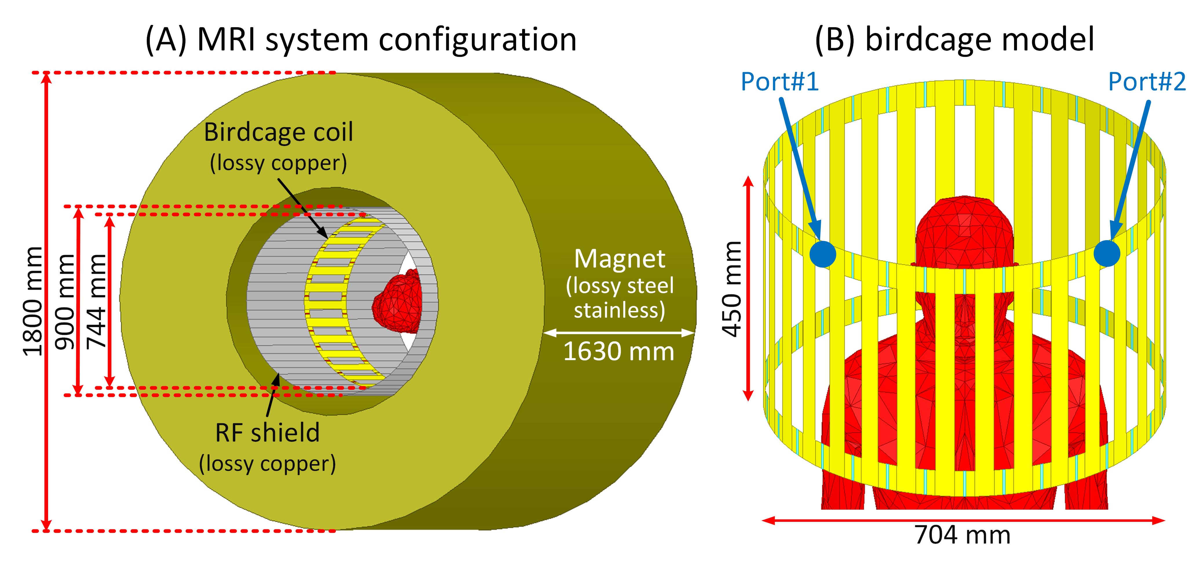
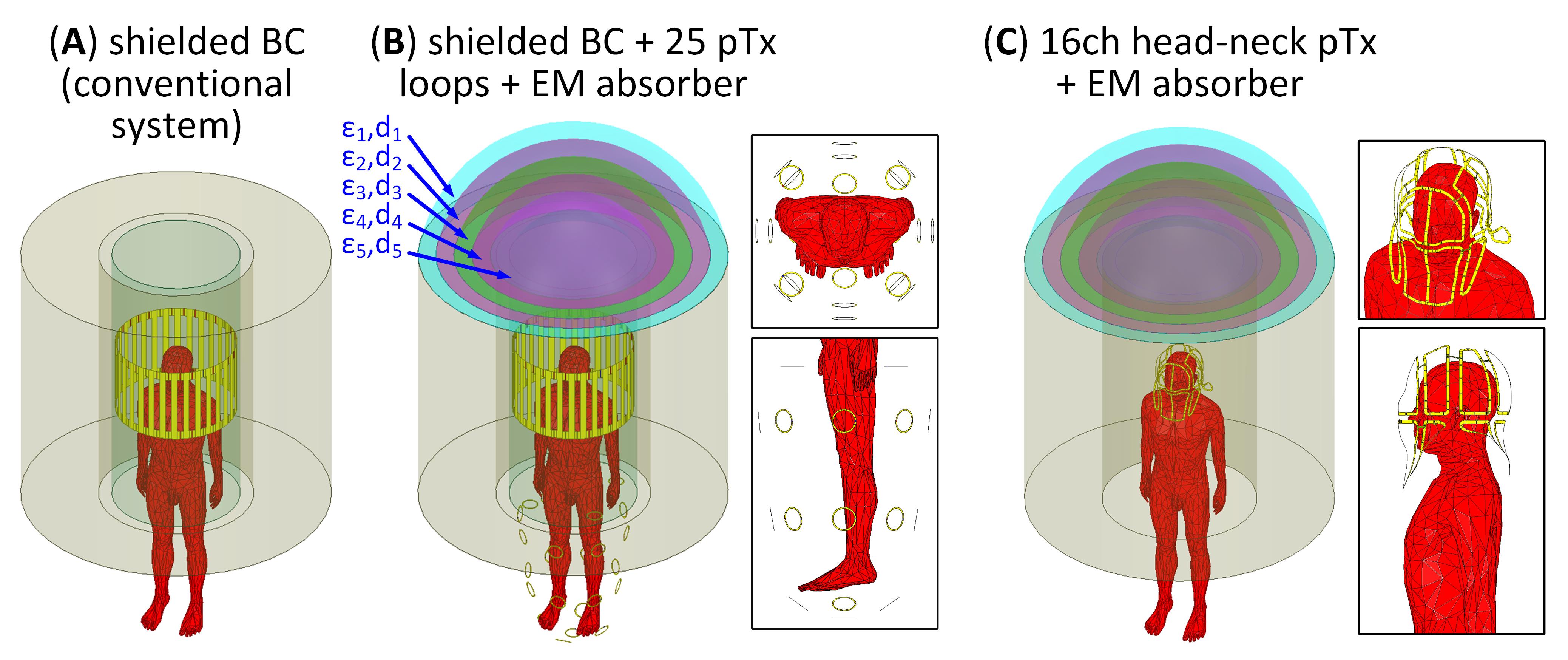
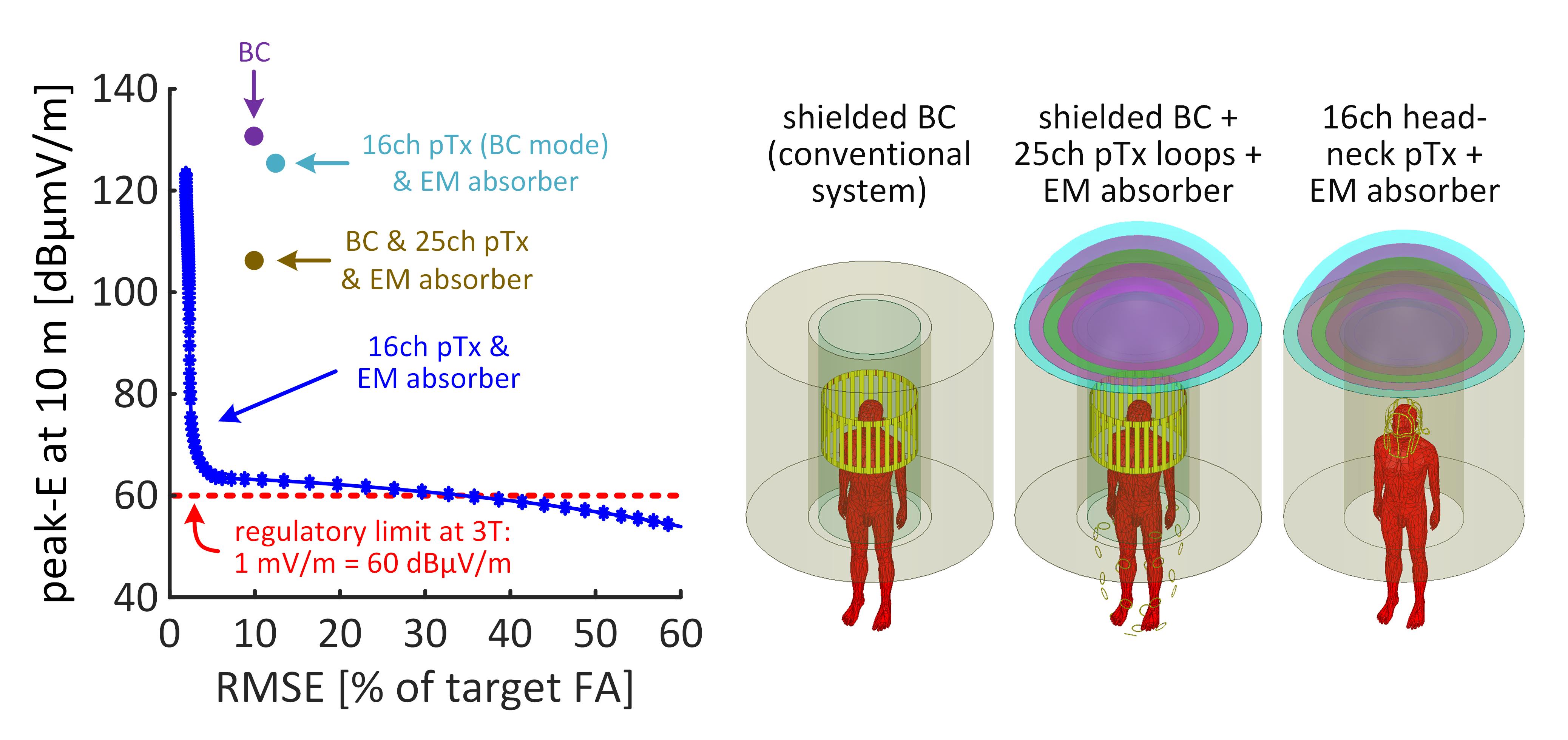
Figure 1 illustrates the conventional MRI system simulated, including superconducting magnet, cylindrical RF shield, and a high-pass CP body birdcage coil. Without mitigation (by a Faraday shield or other method), this geometry exceeds the regulatory limits by 4680-fold for a 300Vrms input. Figure 2 shows the two mitigation strategies tested: (1) a 25-channel loop pTx array positioned around the patient's feet, and an EM absorber placed at the bore’s service-end (Figure 2B) and (2) a 16-channel head/neck pTx array12 replacing the body birdcage coil together with the same EM absorber at the service-end (Figure 2C). In the first mitigation strategy, the pTx loops were strategically positioned away from the head and primarily utilized to minimize peak-E10m. The passive EM absorber used high-dielectric materials optimized for graded interface impedance matching, placed at the bore's service-end. All EM simulations were conducted using ANSYS Electronics with the co-simulation approach, which allowed efficient tuning, matching, and decoupling. All transmit channels (birdcage coil and pTx arrays) were tuned and matched to achieve |S|<-30dB. The pTx channels were ideally decoupled.For all configurations, the radiated E-fields of each Tx channel were exported on 1° isotropic grids on the surface of a 10-m radius sphere. Additionally, B1+-map of each channel was exported on 2-mm isotropic grids in the central head axial slice. Q-matrices13 corresponding to the magnitude of the radiated E-field were computed and compressed using the VOP algorithm14, with a 5% overestimation factor. We computed and reported peak-E10m for a 1Vrms continuous-wave input waveform and for RF-shimming pulses designed with a target flip-angle of 10° across the imaging slice using a 5-lobe slice-selective sinc pulse, with 2-ms duration and 100% duty-cycle. To quantify the radiation mitigation performance of the 25-channel pTx array configuration, we generated an L-curve of the tradeoff between loops pTx power consumption and peak-E10m. In the case of the 16-channel head/neck pTx array, we designed the RF pulses using a least-squares optimization15-17 with a target phase profile of the birdcage mode of the array while constraining the peak-E10m. An L-curve shows the performance tradeoffs between excitation uniformity and peak-E10m.
Results
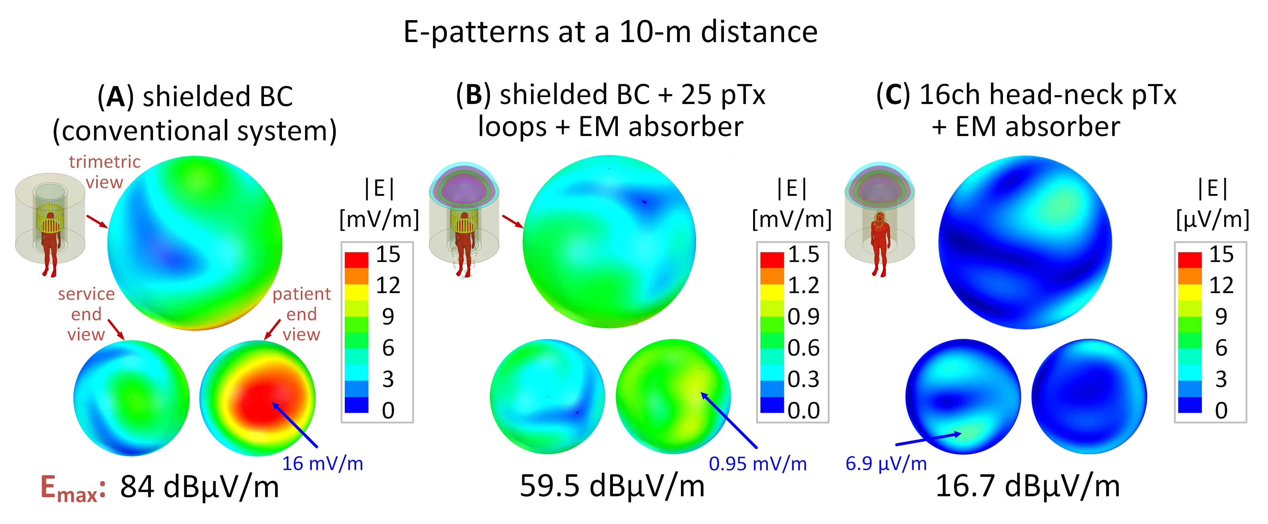
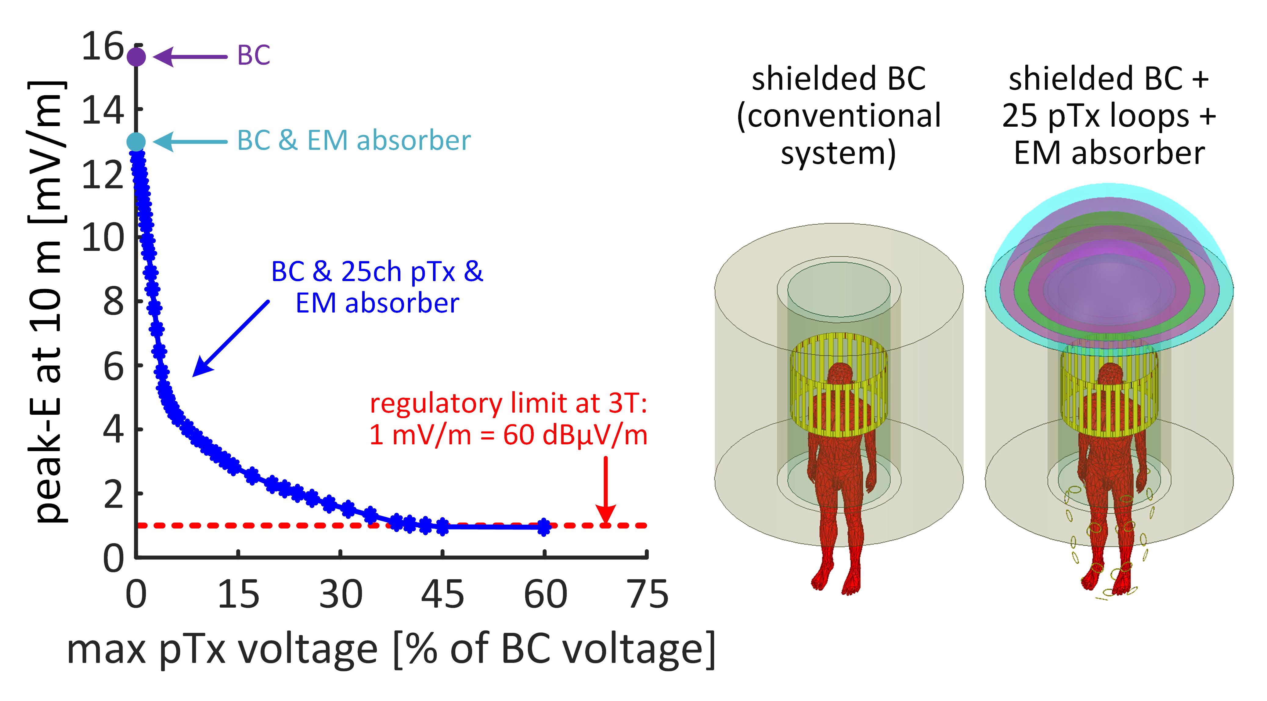
Figure 3 shows the 10-m E-patterns for the three configurations of Figure 2. The conventional system exhibited a peak-E10m of 24dBµV/m higher than the regulation (60dBµV/m at 3T). The utilization of the 25-channel pTx system in conjunction with the EM absorber reduced this by 16-fold and thus below the regulation limit (for this RF drive voltage). Additionally, using the 16-channel head/neck pTx array with the EM absorber yielded a remarkable 2271-fold reduction in the peak-E10m, keeping it 43dBµV/m below the regulation.Figure 4 shows the L-curve tradeoff between peak-E10m and maximum pTx voltage for the 25-channel pTx loop approach, showing that pTx effectively attenuates EM radiation by up to 16-fold without requiring high voltage input. Figure 5 shows the L-curve comparison between peak-E10m and flip-angle uniformity for the 16ch RF-shimming approach. At a constant flip-angle RMSE level (9.9%), the 16-channel pTx system reduces EM radiation by 67.5dBµV/m (2383-fold) compared to the conventional system.
Conclusion and Discussion
Regulations dictate that radiated peak-E10m should not exceed 60dBµV/m for 3T systems, significantly below that found when conventional systems are operated without a Faraday room. Here, we proposed and simulated the ability of pTx methods to reduce radiated peak-E10m levels. The pTx pulses achieved excellent flip-angle excitations within the body while reducing far-field RF radiation by up to 67dBµV/m compared to the CP-driven birdcage coil radiation, ensuring that peak-E10m remained below the regulatory threshold (for 10° flip-angle pulses).Acknowledgements
The authors extend their gratitude to Markus W. May and Boris Keil for the 16-channel head/neck pTx array model, originally designed for 7T imaging, used in this study.References
[1] Harberts DW, Helvoort MV. Sensitivity of a 1.5-T MRI system for electromagnetic fields. 2014 International Symposium on Electromagnetic Compatibility 2014:856-859.
[2] Rearick T, Charvat GL, Rosen MS, et al. Noise suppression methods and apparatus (US Patent No. 9,797,971 B2). U.S. Patent and Trademark Office. 2017.
[3] Huang X, Dong H, Qiu Y, et al. Adaptive suppression of power line interference in ultra-low field magnetic resonance imaging in an unshielded environment. J Magn Reson. 2018;286:52-59.
[4] O'Reilly T, Teeuwisse WM, de Gans D, et al. In vivo 3D brain and extremity MRI at 50 mT using a permanent magnet Halbach array. Magn Reson Med. 2021;85(1):495-505.
[5] Liu Y, Leong ATL, Zhao Y, et al. A low-cost and shielding-free ultra-low-field brain MRI scanner. Nat Commun. 2021;12(1):7238.
[6] Srinivas SA, Cauley SF, Stockmann JP, et al. External Dynamic InTerference Estimation and Removal (EDITER) for low field MRI. Magn Reson Med. 2022;87(2):614-628.
[7] Zhao Y, Xiao L, Liu Y, et al. Predict and Eliminate EMI Signals for RF Shielding-Free MRI via Simultaneous Sensing and Deep Learning. 2022 Asia-Pacific International Symposium on Electromagnetic Compatibility (APEMC) 2022:213-215.
[8] Harberts DW, Helvoort MV. Shielding requirements of a 3T MRI examination room to limit radiated emission. 2013 International Symposium on Electromagnetic Compatibility 2013:1053-1057.
[9] IEC 60601-1-2, Medical electrical equipment - Part 1-2: General requirements for basic safety and essential performance – Collateral standard: Electromagnetic disturbances - Requirements and tests. 2014.
[10] CISPR 11, Industrial, scientific and medical equipment – Radio-frequency disturbance characteristics - Limits and methods of measurement. 2016.
[11] Kazemivalipour E, Guerin B, Wald LL. Simulated radiation patterns of MRI without a shielded room from 0.5 to 7 Tesla. Proc Intl Soc Mag Reson Med 31 2023:0598.
[12] May MW, Hansen SJD, Mahmutovic M, et al. A patient-friendly 16-channel transmit/64-channel receive coil array for combined head-neck MRI at 7 Tesla. Magn Reson Med. 2022;88(3):1419-1433.
[13] Guerin B, Gebhardt M, Cauley S, et al. Local specific absorption rate (SAR), global SAR, transmitter power, and excitation accuracy trade-offs in low flip-angle parallel transmit pulse design. Magn Reson Med. 2014;71(4):1446-1457.
[14] Eichfelder G, Gebhardt M. Local specific absorption rate control for parallel transmission by virtual observation points. Magn Reson Med. 2011;66(5):1468-1476.
[15] Zhu Y. Parallel excitation with an array of transmit coils. Magn Reson Med. 2004;51(4):775-784.
[16] Setsompop K, Wald LL, Alagappan V, et al. Parallel RF transmission with eight channels at 3 Tesla. Magn Reson Med. 2006;56(5):1163-1171.
[17] Cloos MA, Luong M, Ferrand G, et al. Local SAR reduction in parallel excitation based on channel-dependent Tikhonov parameters. J Magn Reson Imaging. 2010;32(5):1209-1216.
Figures