4083
Detailed Investigations into Inward-Outward Ring for Portable MRI1Singapore University of Technology and Design, Singapore, Singapore, 2Chiba University, Chiba, Japan, 3Zhejiang University, Hangzhou, China, 4Jiangsu LiCi Medical Device Co. Ltd, Lianyungang, China
Synopsis
Keywords: Low-Field MRI, Magnets (B0)
Motivation: Halbach arrays that supplies transversal magnetic fields are widely used in portable magnetic resonance imaging (MRI), while the Inward-Outward ring (IO-ring) array that supplies longitudinal magnetic fields has great unrevealed potential yet remains under studied.
Goal(s): We aim to inspect the potential of IO-ring to widen its range of applications in portable MRI.
Approach: By identifying the key geometric parameters and examining their effects on field strength and pattern. Analyses were conducted and the potential applications were discussed.
Results: IO-ring is shown to be a promising candidate for providing flexible magnetic field patterns for portable MRI in different application scenarios.
Impact: The relationship between all design parameters of IO-ring and the corresponding field pattern, as well as some intuitive variants of IO-ring design has been explored, providing new insight to PMA design for portable MRI.
Introduction
Permanent magnet array (PMA) designs are widely used for portable magnetic resonance imaging (MRI) due to low power consumption and small footprint. For the recent effort on low-field portable MRI, cylindrical magnet arrays are popular e.g., Halbach array1 with dipolar transversal fields and inward-outward (IO) ring pair with dipolar longitudinal fields2,3,4,5. The former is more well-known than the latter, but the latter offers unique features. Due to the field direction, an IO-ring pair can work with high performance coils designed for MRI systems and allow easy pre-polarization. It has decent space between the two rings for potential interventions, and design variance for wide applications (e.g., single-sided array6). It has much unrevealed potential and remains understudied. Here, investigations on the design parameters of IO-ring are presented to reveal its potential.Methods
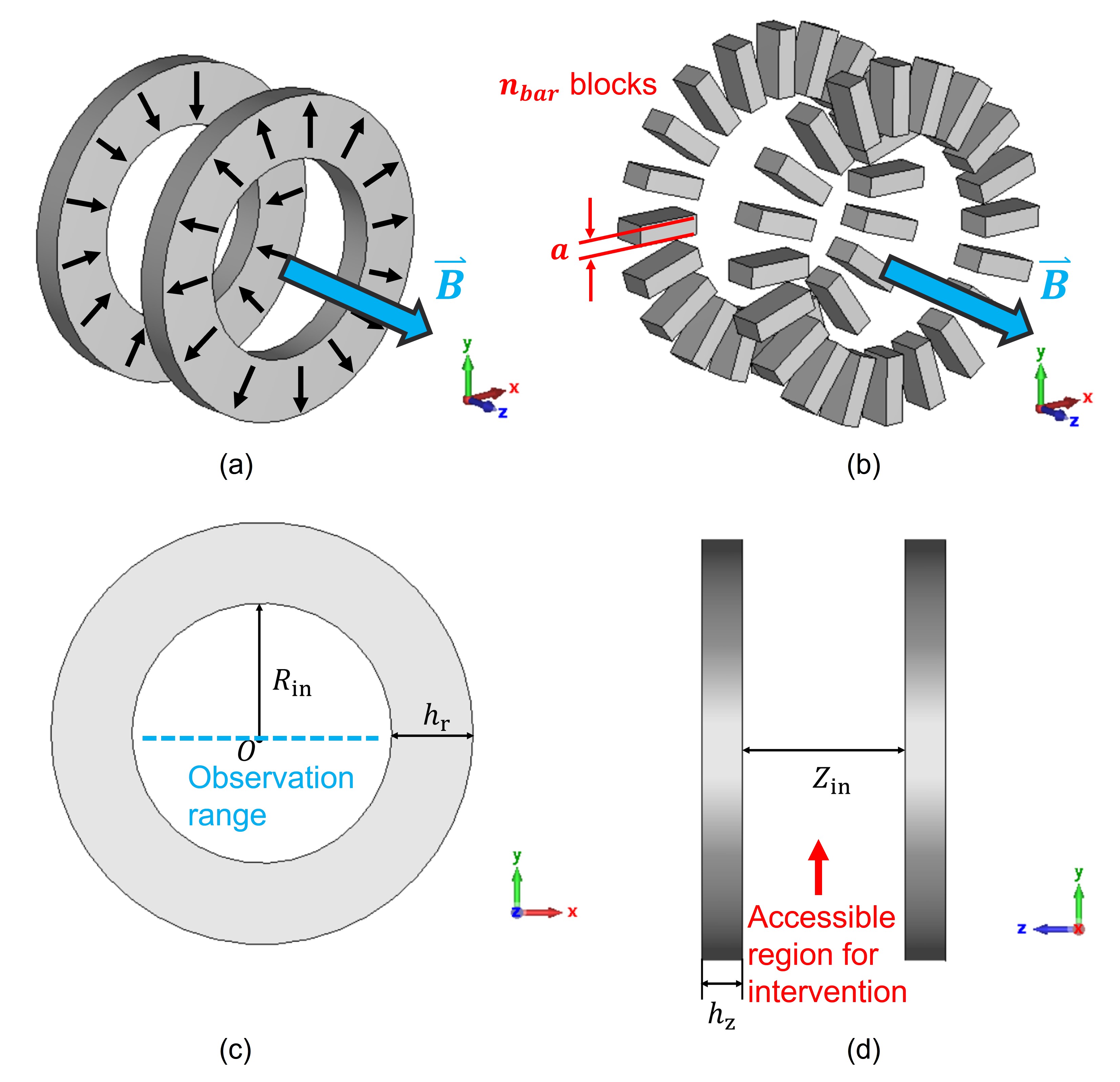
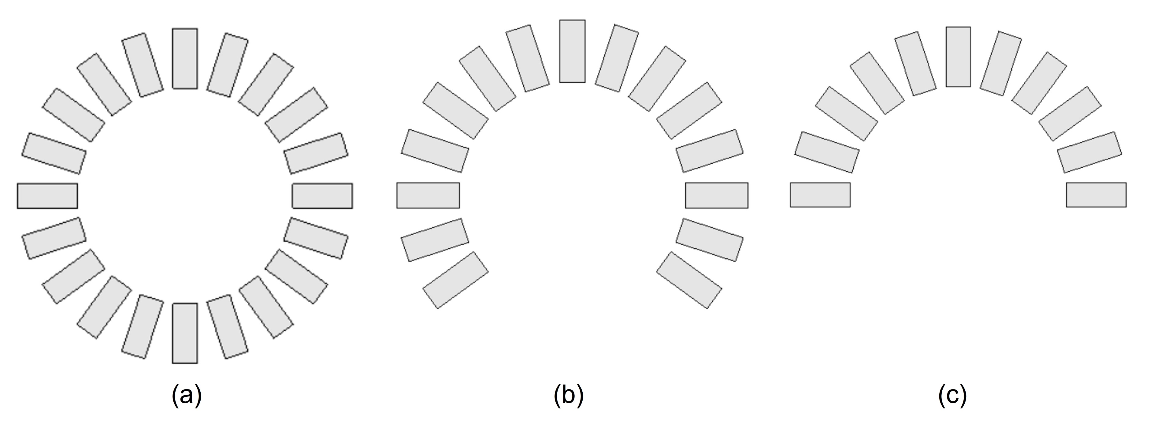
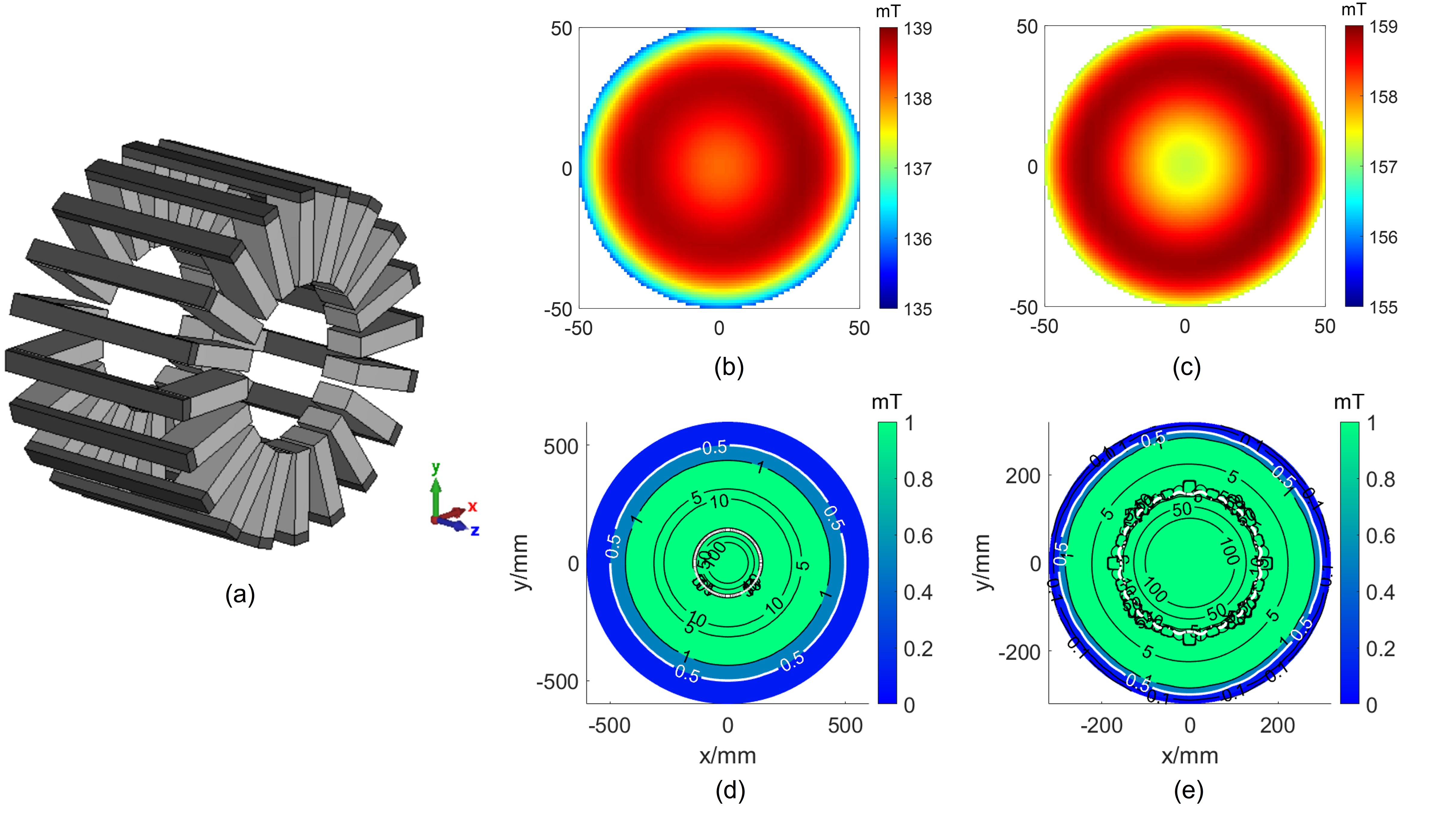
The basic unit for study is a single IO-ring pair as shown in Fig.1(a). The following parameters define the geometry: The inner radius $$$R_{in}$$$, the distance $$$Z_{in}$$$ between the inner surfaces of the two rings, the radial thickness $$$h_r$$$, and the axial thickness $$$h_z$$$. In practice, arc-shaped/ring-shaped magnets are less available. Therefore, the IO-ring is discretized using cuboid magnets2, as shown in Fig.1(b) with $$$n_\text{bar}$$$ blocks and a circumferential length of $$$a$$$ for each block. For examination, the range of the parameters were set to cover a full transition of the field pattern, with $$$a=20$$$mm and $$$n_\text{bar}=16$$$. Since the magnetic field from an IO-ring pair is mainly axial, only the z-component is examined. Also, as the resulting field is concentric, each field map is represented with a curve of field strength along the x-axis without loss of generality. Partial IO-ring configurations were inspected, too, for potential single-sided applications. Fig.2(a)-(c) show the cross-sectional view of different configurations.Results & Discussions
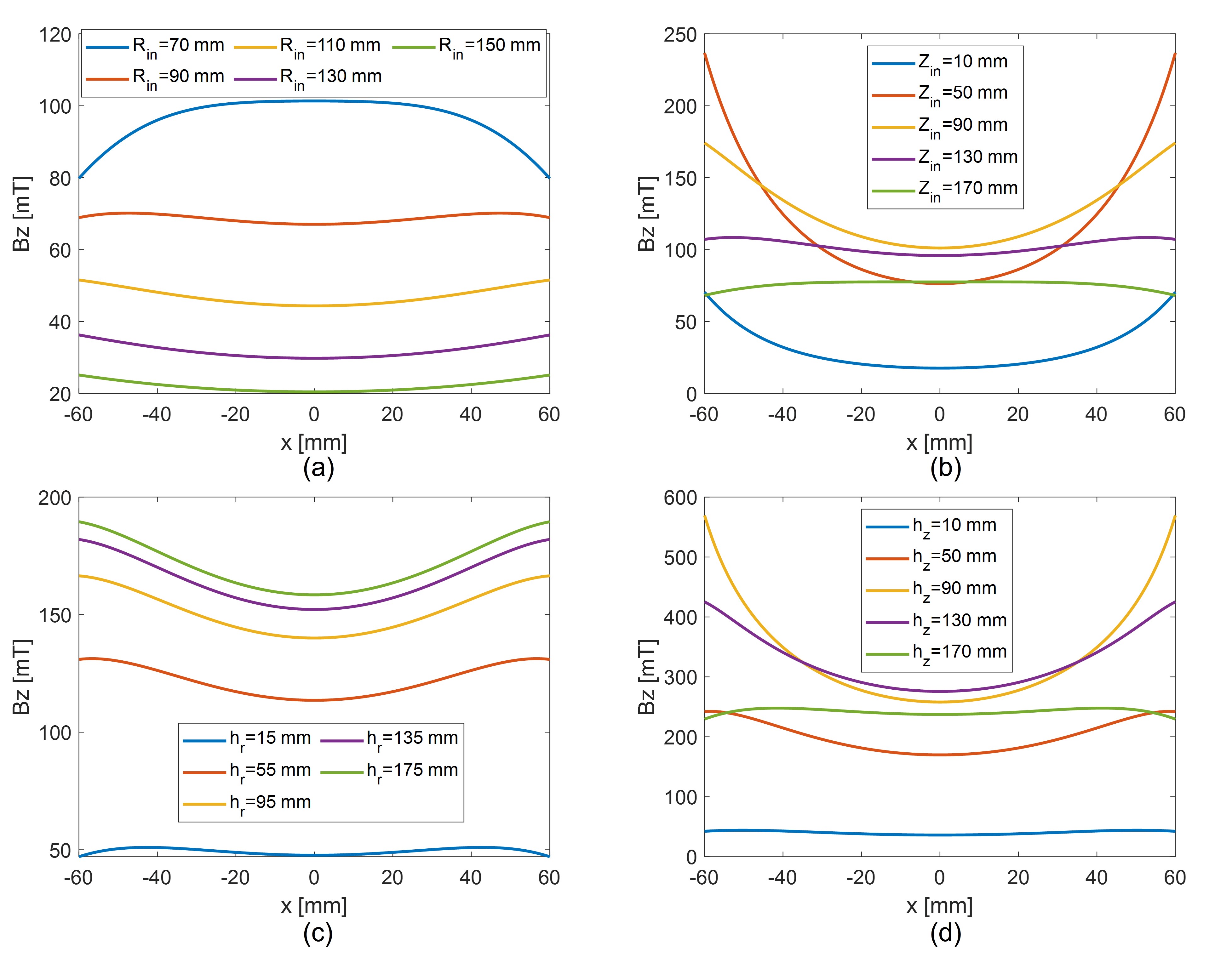
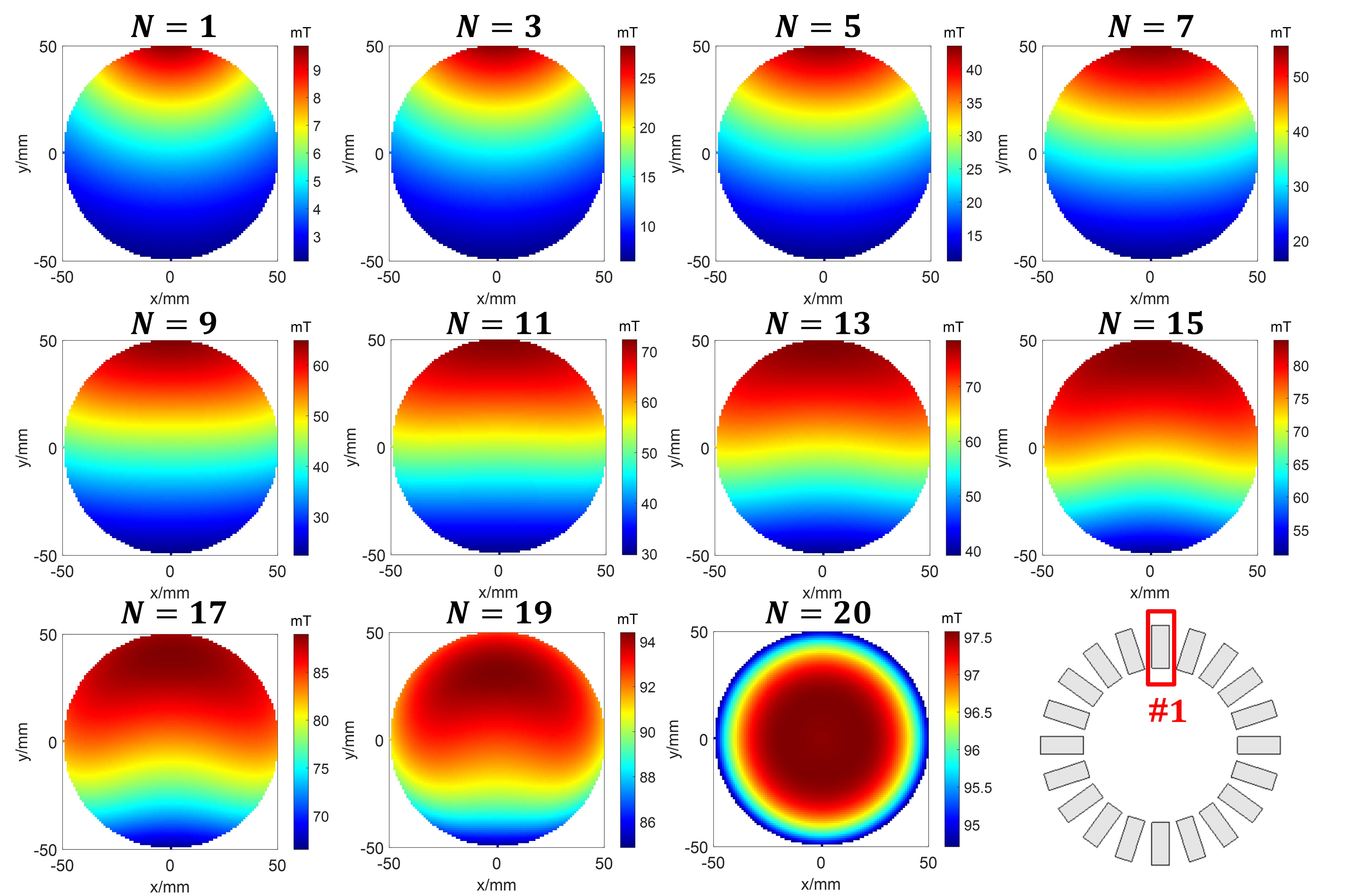
Fig.3 shows the resulting Bz field along the x-axis when each parameter is swept. In Fig.3(a), as $$$R_{in}$$$ grows, the resulting field line transforms from convex downward to flat, then concave upward. In Fig.3(b), when $$$Z_{in}$$$ increases, the shape of curves has the opposite transition. When $$$Z_{in}$$$ is very small, the field strength decreases due to the field cancelling between the two rings. In Fig.3(c)-(d), $$$h_r$$$ has the same type of transition as $$$R_{in}$$$, and $$$h_z$$$ the same as $$$Z_{in}$$$, while $$$h_r$$$ and $$$h_z$$$ have less impact than $$$R_{in}$$$ and $$$Z_{in}$$$. Overall, it is seen from Fig.3 that a relatively homogeneous magnetic field pattern can be achieved with a single IO-ring pair with four geometric parameters tuned accordingly. Fig.4 shows the trend of magnetic field pattern as the number of magnets in one ring sweeps from 1 to 19 with a step of 2 blocks added symmetrically with respect to the vertical axis for a partial IO-ring. the full IO-ring pair with $$$n_\text{bar}=20$$$ is included. With increases, the resulting magnetic field shows monotonic gradient along the y-direction. When it becomes a semi-circle at $$$n_\text{bar}=11$$$, the gradient shows high linearity with $$$R^2=0.995$$$. The partial IO-ring variant is supplementing to regular IO-rings with concentric fields. It can be a single-sided design for spine imaging6. By adjusting the location and orientation angle of individual magnets in a half IO-ring pair, gradient with high linearity can be achieved. IO-ring can also be coupled with ferromagnetic yokes to further improve field homogeneity. As shown in Fig.5(a), each pair of magnets are connected by a piece of iron yoke. The fields generated by this IO-ring pair without and with iron yoke are simulated by CST Studio Suite, shown in Fig.5(b) and (c), respectively. With the iron yoke, both field homogeneity and strength are improved. Fig.5(d)-(e) show the 5-Gauss zones. The iron-yoke case has a 5-Gauss zone 36% of that non-iron-yoke case. Therefore, adding ferromagnetic yoke can effectively confine the magnetic field within the bore with improved homogeneity.Conclusion
In this abstract, the properties of IO-ring are examined. By tuning the geometric design parameters, field maps with various patterns can be obtained for different applications, where magnetic fields with high homogeneity are available. Also, the variants of IO-ring, such as the partial IO-ring, can provide gradient field with high linearity, which can be further applied for MRI. Besides, ferromagnetic yokes can be combined with IO-ring for improved homogeneity and compactness. With the unique features and design flexibilities, the IO-ring structure has great potential in more MRI applications with portability in the near future.Acknowledgements
No acknowledgement found.References
1. K. Halbach, Design of permanent multipole magnets with oriented rare earth cobalt material, Nuclear instruments and methods 169 (1) (1980)305 1–10. 2. G. Aubert, “Permanent magnet for nuclear magnetic resonance imaging equipment,” July 26, 1994. US Patent 5,332,971 3. G. Miyajima, Cylindrical permanent magnet apparatus, Japanese Patent JPS60210804A (Oct.23, formally Apr. 4, 1984 1985). 4. E. Nishino, Magnetic medical appliance, UK Patent, GB2112645A (Jul.27 1983). 5. Z. H. Ren, W. C. Mu and S. Y. Huang, "Design and Optimization of a Ring-Pair Permanent Magnet Array for Head Imaging in a Low-Field Portable MRI System," in IEEE Transactions on Magnetics, vol. 55, no. 1, pp. 1-8, Jan. 2019, Art no. 5100108, doi: 10.1109/TMAG.2018.2876679. 6. Ting-Ou Liang, Erping Li, Wenwei Yu, Shao Ying Huang, Compact and Lightweight Single-sided Inward-outward (IO)-ring permanent magnet array for back imaging, ISMRM (2023).Figures