4082
MRI in-bore wireless link fidelity investigation with integrated ultra-wide-band antennas1Stanford University, Stanford, CA, United States
Synopsis
Keywords: RF Arrays & Systems, MR Fingerprinting
Motivation: Optimum antenna allocation within the MRI bore is essential for reliable wireless link establishment.
Goal(s): Our goal was to identify a sweet spot for in-bore antenna integration.
Approach: We utilized time domain pulse distortion metric to evaluate various link fidelities.
Results: Study results suggest that the antenna allocation at the middle of the birdcage circumference may produce the minimum pulse distortion and interference.
Impact: A time domain pulse distortion metric may provide useful design information to system engineers for reliable in-bore wireless link establishment over a desired bandwidth.
Introduction
MRI wireless coil technology has enormous potential to allow versatile coil design, to eliminate the root cause of cable related safety hurdles, and to improve clinical workflow1. Among numerous aspects of going wireless, understanding the in-bore electromagnetic environment is an important aspect to establish a reliable data link that often requires a large bandwidth2. In line with a previous simulation study3, we investigate wireless system fidelity factors4 (SFF) which is a cross correlation metric of time domain pulse distortion over various Tx-Rx ultra-wide band (UWB) antenna arrangements within a shielded mockup bore. Its computation may help to allocate antenna at a sweet spot. In addition, group delay and signal dispersion were quantified for the bandwidth of interest. Birdcage RF coupling to UWB antennas were also quantified to understand the degree of interference within a bore.Methods
Low-profile patch type UWB antennas (FXUWB10, Taoglas) were used to assess wireless links for the bandwidth of interest, 3-5GHz, within a mockup bore (ESP – 37cm diameter, GE Healthcare)5. Five discrete Tx antennas marked as (Tx.I, C, S, R, and L) were positioned over an anthropomorphic phantom in Figure 1 (a). Two Rx antenna locations, one at the middle of birdcage (Rx.C) in Figure 1 (b) and one at the bore end (Rx.E) in Figure 1 (c), pair with each Tx, constituting two pair groups. The phantom was positioned at the iso-center so that Rx.C was symmetrically positioned toward each Tx, whereas Rx.E was in a skew position toward the Tx. System transfer function, H(ω) was measured from complex S21 over 3-5GHz using a VNA (E5071C, Agilent Technologies) in Figure 2 (a) to calculate receive waveforms with a test gaussian Tx pulse. With H(ω) and Tx in Figure 2 (b), Rx time domain waveforms were simulated by the simple formula in the reference4 for each Tx-Rx pair using Matlab shown in Figure 3. In addition, group delay and SFF were calculated as a quantitative metric to assess overall wireless data transfer fidelity in Figure 4. To quantify position dependent MRI RF coupling, S21 was measured between the birdcage port and each UWB with linear and quadrature drives at 127.75MHz.Results
The unwrapped phases of H(ω) in both pair groups show monotonic decreases over the frequency band in Figure 2 (a). Rx.C pairs (left side figure in Figure 2 (a)) show relatively small phase variations, compared to the other pair group, which is attributed to the symmetric arrangement of Rx.C toward Tx. In addition, |H(ω)| in Rx.C pairs show higher amplitude in general than the other because of the closer antenna pair distance. In Figure 3, reconstructed Rx waveforms for the given Tx (2ns width) represent different in-bore wave propagation environments. Those in Rx.C clearly show monotonic delay and less ringing in Figure 3 (a). In contrast, those in Rx.E exhibit heterogeneous delays and more dispersed ringing (up to 8ns) in Figure 3 (b). The calculated group delay distribution in Figure 4 (a) and the SFF in Figure 4 (b) reflect these signal trends in comparison to the two pair groups. For instance, the Tx.S - Rx.E pair produces the minimum SFF, which holds the largest dispersion and delay. The overall SFF with Rx.C pair resulted in a higher mean value, 0.87 vs. 0.82, suggesting preferable Rx antenna placement in close line of sight toward Tx within a bore. In Figure 5, the largest imaging RF coupling case is -28dB at QD, noting that Rx.E is closely located to the birdcage end-ring. Coupling variations on Tx antennas indicate position-dependent local electric field variations within the birdcage.Discussion and conclusion
The predictable and reliable data link within a bore environment is essential for wireless MRI. SFF metric with a choice of data bandwidth of interest can be a useful tool for that purpose. Like the previous simulation study3, the group delay dispersion becomes wider when an antenna pair is in a skew position with a farther distance within the mockup bore, degrading system fidelity factors. Simulated Rx waveforms indicate that the antenna arrangement in close line-of-sight can provide less ringing and dispersion. Accordingly, this finding assumes that antennas are integrable within a volume coil without significant system alternations. Imaging RF interference measurement suggests that the center of birdcage circumference can be a sweet spot for allocating Rx antenna, where minimum local E-field interaction occurs. However, noting that kilo-watt range of imaging RF peak power, interference mitigation strategies shall be needed within the wireless front-end system.Acknowledgements
We thank GE Healthcare for research support and NIH 1RO1 EB019241References
- Perspectives in Wireless Radio Frequency Coil Development for Magnetic Resonance Imaging by Lena Nohava et al, frontiers in Physics 2020
- Aggarwal K, Joshi KR, Rajavi Y, Taghivand M, Pauly JM, Poon AS, Scott G. A Millimeter-Wave Digital Link for Wireless MRI. IEEE Trans Med Imaging. 2017 Feb;36(2):574-583.
- UWB antenna system fidelity investigation for wireless MRI, ISMRM 2021 # 1409
- Gabriela Quintero at al., System Fidelity Factor: A New Method for Comparing UWB Antennas, IEEE trans. On AP 2011
- Thomas Foo et al., Lightweight, compact, and high-performance 3T MR system for imaging the brain and extremities, MRM 2017
Figures
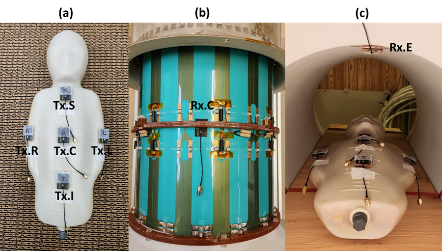
Figure 1. Photographs of UWB Tx and Rx antenna allocations, and an anthropomorphic phantom placement within a bore for wireless link system. Five discrete Tx antennas (Tx.I,C,S,R.L) are positioned on top of the phantom in (a). Two distinct Rx placements, Rx.C & Rx.E are positioned in the middle of the birdcage between two adjacent rungs (b) and at the end of bore ceiling (c), respectively. The anthropomorphic phantom was placed in iso-center so that Rx.C was symmetrically positioned toward Tx’s, whereas Rx.E was in a skew position toward the Tx antennas.
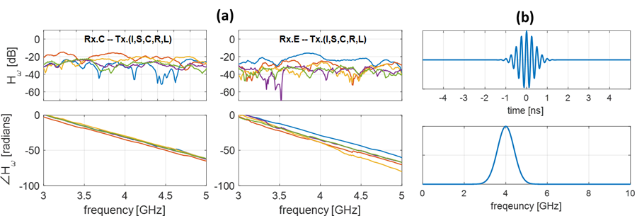
Figure 2. Measured system transfer function in terms of magnitude and unwrapped phase over 3-5GHz for each Tx-Rx pair in (a) and test gaussian Tx pulse (2ns width) in time and frequency domain in (b). The left side of Figure (a) with Rx.C – Tx pairs show higher transfer magnitude in general and exhibits less phase dispersion among Tx-Rx pairs, compared to the Rx.E – Tx pair group.
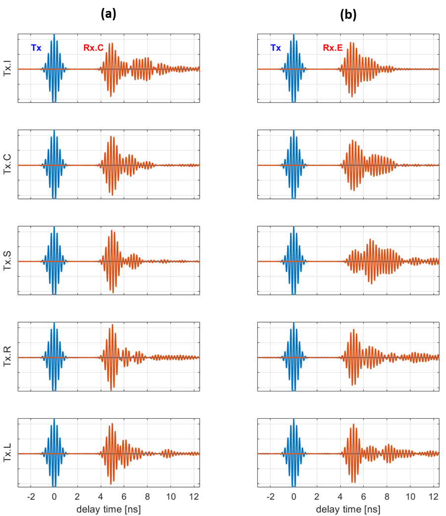
Figure 3. Simulated Rx waveforms and delays relative to Tx versus time between two Tx-Rx pair groups. Red colored waveforms of Rx.C pair group in (a) show more uniform delay and less ringing among pairs. In contrast, those of Rx.E in (b) exhibit heterogeneous delays and dispersed ringing.
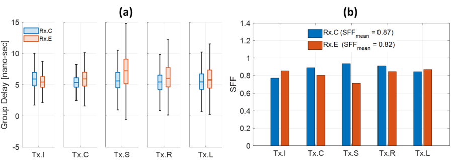
Figure 4. Comparison of measured group delay distribution in box-chart (a) and corresponding SFF calculations (b) between two Rx pair groups. The quantified group delays in quartiles indicates higher phase dispersion with the skewed antenna pair arrangements at farther distance. SFF calculation results in higher mean fidelity numbers with the Rx.C pair group in (b), which reflects group delay indications in (a).
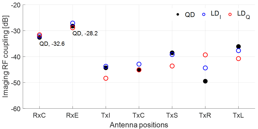
Figure 5. MRI birdcage RF coupling measurement toward UWB antennas as a function of their positions within the mockup bore with linear and quadrature drives. The highest coupling case at quadrature drive is -28.2dB where Rx.E is closely located to the end-ring of birdcage. Coupling to Tx antennas are less than those of Rx antennas in places farther from the birdcage conductors. These variations indicate position dependent local electric field distribution within the birdcage.