4080
MRI4ALL Hackathon: Under a Week Build of Open-Source Gradient Coils for a Low-Field MRI1Department of Biomedical Engineering, Yale University, New Haven, CT, United States, 2Department of Biomedical Engineering, Columbia University in the City of New York, New York City, NY, United States, 3Bernard and Irene Schwartz Center for Biomedical Imaging, New York University Grossman School of Medicine, New York City, NY, United States, 4Athinoula A. Martinos Center for Biomedical Imaging, Department of Radiology, Massachusetts General Hospital, Harvard Medical School, Charlestown, MA, United States, 5BARNLabs, Muenzkirchen, Austria, 6NIST: National Institutes of standards and Technology, Boulder, CO, United States, 7LaGuardia Studio, New York University, New York City, NY, United States, 8Division of Medical Physics, Department of Diagnostic and Interventional Radiology, University Medical Center Freiburg, Faculty of Medicine, University of Freiburg, Freiburg, Germany, 9Center for Advanced Imaging Innovation and Research (CAI2R), Department of Radiology, New York University Grossman School of Medicine, New York City, NY, United States
Synopsis
Keywords: Low-Field MRI, Low-Field MRI
Motivation: High production costs limit the accessibility of MRI. To break this accessibility and cost barrier, we demonstrate that affordable gradients can be designed and built in less than two weeks using open-source software and conventional 3D printing.
Goal(s): To develop X, Y, and Z gradients for an ultra low-field Halbach MRI.
Approach: We used open-source software to design the gradients. The casing was 3D printed, and the coils were manually wound. The fields were measured using an open-source field-mapping probe.
Results: We constructed gradients that generated magnetic fields with great correspondence to simulated fields. 2D images were acquired with a fast spin-echo sequence.
Impact: Open-source software can be used to design, build, and test MRI gradient coils in a quick and affordable manner. This demonstrates that open-source software for design of MRI hardware can lead to more accessible MRI.
Introduction
The MRI4ALL hackathon was hosted at New York University (NYU) in New York City, USA, in October 2023, in an effort to make MRI hardware and software more accessible. ~50 MRI researchers came together to build a low-field MRI scanner during this less than a week long event. Subgroups of researchers each developed the main magnet, gradient and shims, RF coils, and software. This abstract details the work of the gradient team which successfully designed, built, and tested the gradient system.Methods
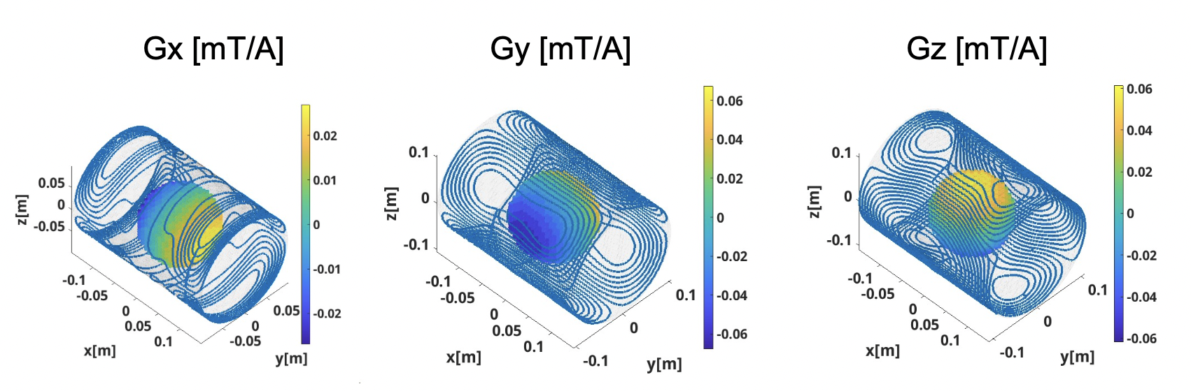
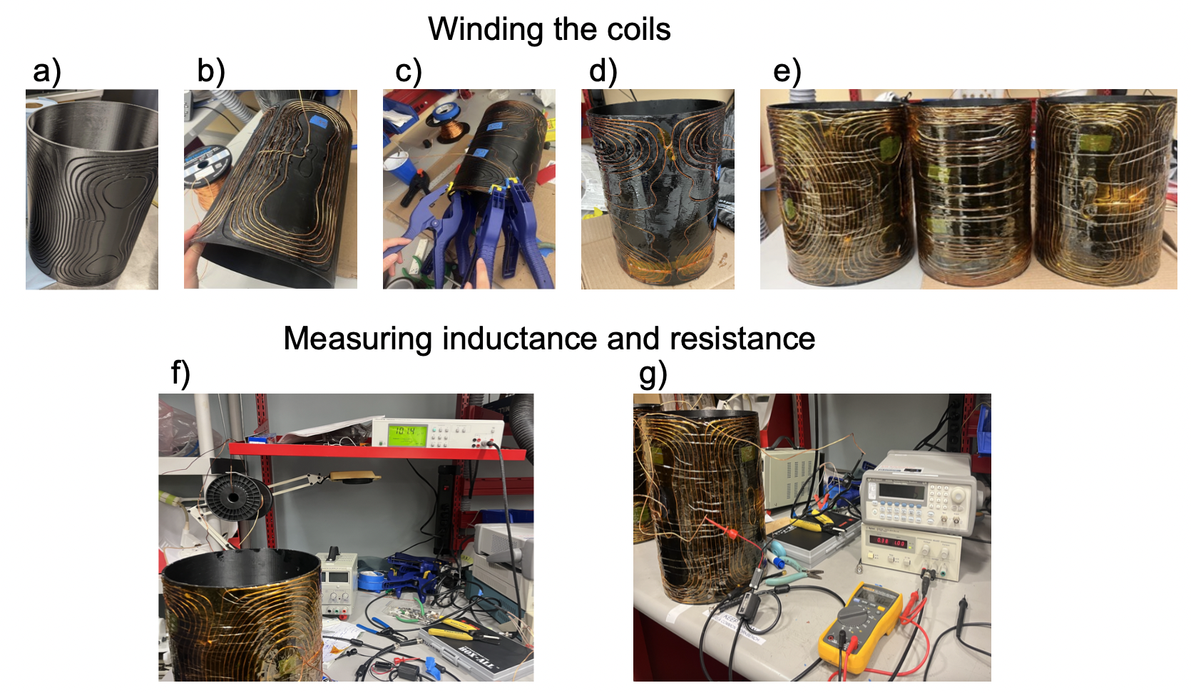
Gradient coils were designed using CoilGen1: an open-source gradient coil software package. Our design was inspired from CoilGen’s example Halbach gradient coils, modified to fit the dimension, sensitivity, and FOV requirements (14 cm) of the magnet (Fig1). The gradient coil casing with coil winding grooves were 3D printed (Fig2a) during the week before the hackathon (taking 48 hours per gradient).During days 1-4, 16AWG copper wire was wound into the coil grooves through a four-step process (Fig2). First, the wire was inserted into the coil casing segment-by-segment, taped, and then superglued (2b). Next, the coils were epoxied to the casing to prevent coil movements from torquing during gradient switching in imaging (2d). To reduce unwanted stickiness due to incomplete hardening of the epoxy, each gradient coil was covered with a layer of Kapton tape (2e). Clamps were used to secure the wires during the winding, which both facilitated the curing and greatly hastened the winding process (saving over 4 hours for each coil) (2c). The whole winding process required that three team members work on a single gradient simultaneously.
Following complete winding, the inductance of each gradient coil was measured with an automatic RCL meter (Fig2f). The coil resistance was measured using the voltage across the coil with a DC power supply providing 1Amp current (Fig2g).
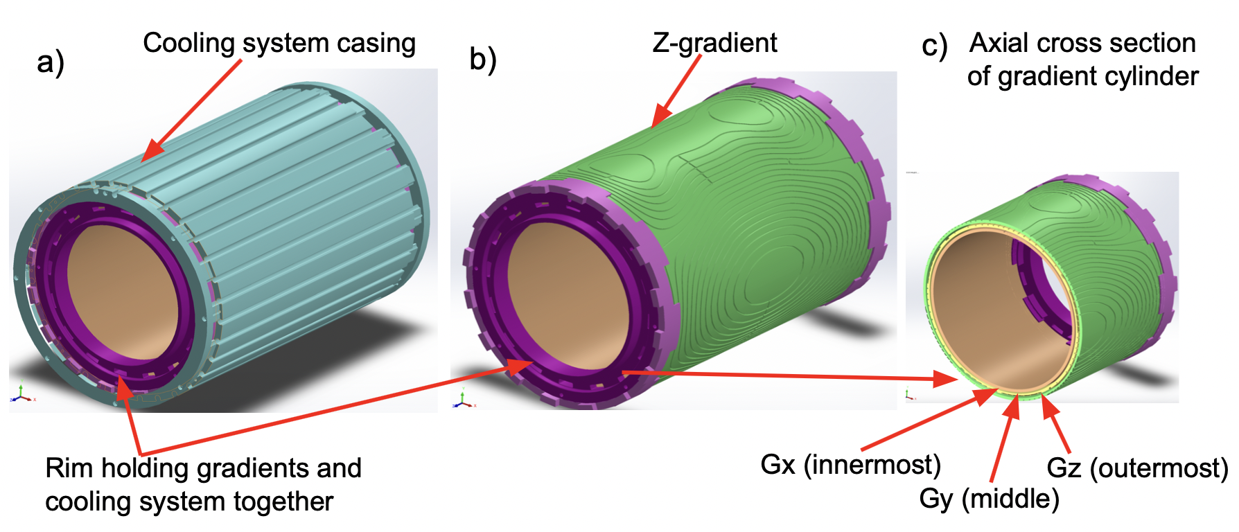
During days 5-6, gradient casings containing the X, Y, Z coils were assembled into a single cylindrical structure. A layer of water cooling tubes were designed to be sandwiched by the magnet and gradient coils to simultaneously chill them (Fig3a). The gradient coils were inserted into the main magnet following the cooling structure (3b-c). After installation, the effectiveness of the cooling system was verified by measuring the center FOV temperature when the gradient coils were turned on (with 1Amp current) and off using a forward looking infrared (FLIR) thermal camera.
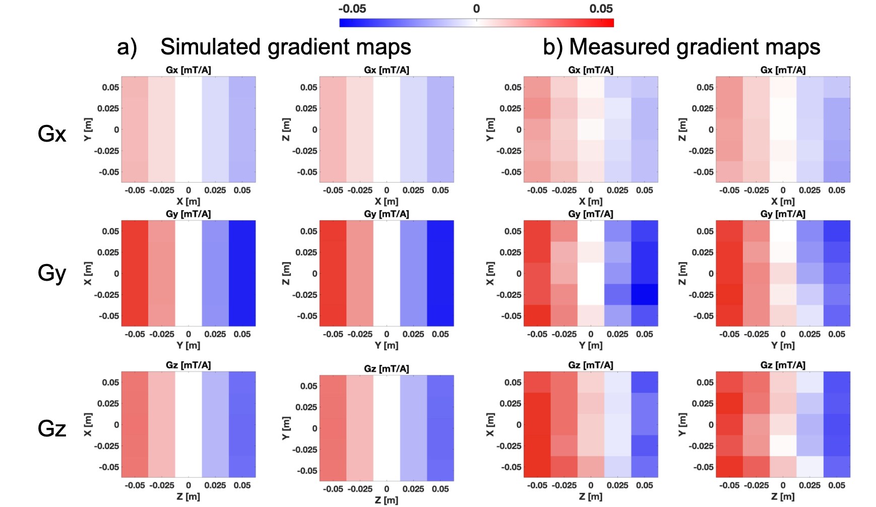
The spatial distribution of the magnetic field created by each gradient coil was measured using an open-source field mapping system with a 5x5x5 grid spanning a FOV of 10cm in each direction (Fig4). The gradient strengths for each gradient coil were calculated by first-order spherical harmonic fitting.
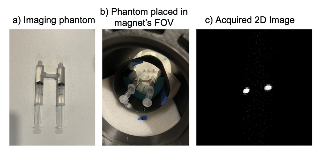
Imaging experiments were performed at 1.825 MHz with a fast spin-echo train with 40 µs rectangular RF excitation and refocusing pulses (Fig5). The resolution was 300x80, FOV ~14 cm, echo spacing 13ms, with total acquisition time 36s.
Results
The measured inductances of gradient coils (49, 73, and 101 µH) was nearly identical to the simulations (48, 72, and 97 µH) for Gx, Gy, and Gz, respectively. The corresponding resistance measurements (0.36, 0.38, and 0.45 Ω) were slightly larger than simulations (0.23, 0.28, and 0.38 Ω).The measured gradient coil sensitivities (calculated from linear-fitting: Gx: 0.39, Gy: 0.88, Gz: 0.85 mT/m/A) are similar to those generated by the CoilGen simulations: Gx: 0.35, Gy: 0.92, Gz: 0.86 mT/m/A (Figure 4).
Fig5c shows the fast spin-echo image of a syringe phantom (5a, 5b).
Discussion
The results show that it is feasible to design and build open-source gradient coils for a low-field Halbach array MRI in a short time span. The constructed gradients were similar to the simulations across various parameters (maximum percent error is 4% for inductance and 10% for sensitivity), showing that the CoilGen software is a reliable tool for gradient coil design. Importantly, the total material cost for these coils was under $1000, demonstrating the feasibility of affordable open-source MRI. All the tools and designs for this project are shared in a publicly available GitHub repository (https://github.com/mri4all).Conclusion
Open-source software can be used to rapidly design and fabricate gradient coils for low-field MRI, which demonstrates its feasibility for more affordable and accessible MRI hardware.Acknowledgements
The authors would like to thank all participants at the MRI4All Hackathon for their collaboration and helpful insights, and especially Tobias Block, Sairam Geethanath, Clarissa Cooley, Leeor Alon, and Jason Stockmann (gradient team lead) for organizing the event.
We would also like to thank Sebastian Littin and Philipp Amrein for providing guidance on gradient design done with CoilGen.
The hackathon was supported by NYULangone Health. Data and code availability: https://github.com/mri4all.
References
1. Amrein, Philipp, et al. "CoilGen: Open‐source MR coil layout generator." Magnetic Resonance in Medicine 88.3 (2022): 1465-1479.Figures