4078
Design of a segmented RF shield to minimize eddy currents on low-field Halbach MRI systems1Radiology, C.J. Gorter MRI Center, Leiden University Medical Center, Leiden, Netherlands, 2Microelectronics, Terahertz Sensing, Delft University of Technology, Delft, Netherlands
Synopsis
Keywords: Low-Field MRI, Low-Field MRI, Shielding, Eddy-currents
Motivation: Eddy-currents induced in the shielding layer placed between the gradient coils and RF transmit coil can create artefacts and lead to longer echo times. Reducing these currents by segmenting the shield while keeping the noise-reduction properties is important for low-field point-of-care systems.
Goal(s): Minimizing eddy currents for transverse B0 magnets while maintaining shielding effectiveness.
Approach: The segmentation locations are chosen by taking into account the wire pattern of the RF coil and gradient-induced eddy current simulations.
Results: The suggested shield results in a decrease in the measured eddy current effects by a factor of 15, with only a noise increase of 4%.
Impact: The proposed shield reduces eddy current effects by a factor of 15, giving the opportunity to achieve shorter echo-times and higher slew rates with fewer distortions on point-of-care low-field systems.
Introduction
MRI systems have a shielding layer placed between the gradient coils and RF transmit coil. This acts as a shield at the RF-frequency, minimizing noise coupled into the measurement, and reducing coupling between the RF and gradient coils. At the same time this layer should be transparent to the gradient fields to minimize eddy currents. A substantial body of work exists for conventional MRI systems with an axial B0 field1-5, with much less literature on transverse B0 fields6-8.In this work we consider the design of an RF shield for low field point-of-care Halbach based MRI devices. The lower Larmor frequency results in a requirement for a thicker shield due to increased RF skin-depth which leads to increased eddy-currents. The design must also take into account the transverse B0 field meaning that gradient coil geometries are different than for conventional systems, and that these systems use primarily solenoidal RF-coils.
Here, we simulate the eddy-currents and the optimal segmentation positions are determined by combining these results with the wire patterns of the RF-coil.
Methods
The shield is designed for a 52 mT Halbach system9, and fits around a 257 mm diameter, 505 mm length, 3D printed cylinder. A 25 µm thick copper laminate is used to form a cylinder, which is closed at both ends using two 0.5 mm thick circular aluminum plates.The gradient coil wire patterns10, together with the shield are simulated using a low-frequency time-domain solver in CST. A smooth step function with a ramp time of 200 µs is applied to each gradient and the corresponding eddy-current density patterns created in the shield are simulated after the ramp up time. Subsequently, these current densities are used to determine where to place the segmentations to interrupt the eddy current pathways. To maintain the shielding properties, previous work suggests that segmentations should be parallel to the current density of the RF coil1.
To measure the magnitude and time evolution of the eddy-currents a gradient (x, y or z) with amplitude 10 mT/m and ramp time 200 µs is applied, followed by a variable delay and then a 90°-readout RF pulse. The peak of the MR spectrum is plotted as a function of the variable delay after the gradient pulse. A second method measures the inductance of the gradient coils with the shield in place, and the changes in inductance introduced by segmenting the shield: the amount of coupling between the gradient coils and the shield is reflected by the mutual inductance. Finally, a noise level is obtained by measuring the noise sensitivity profile, fitting a polynomial and taking the maximum value11.
Results
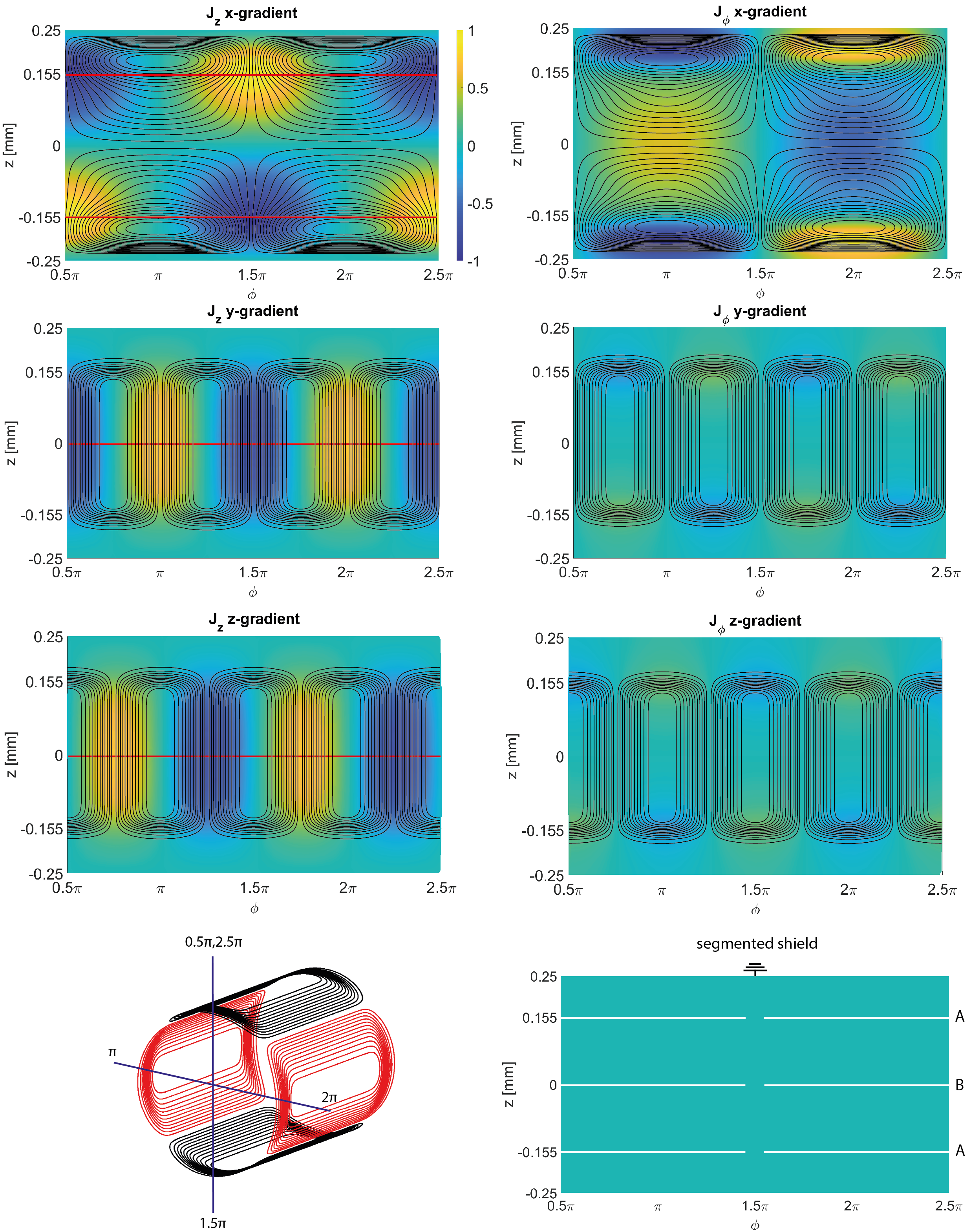
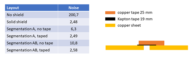
Figure 1 shows the eddy-current densities on the shield and the proposed segmentations shown as red lines. The majority of the current density in the solenoidal RF-coil is in the φ-direction. Therefore, segmentations in this direction are made. A grounding lane is chosen such that it lies directly above the return path of the solenoidal coil. Simulations show that segmentations through the eddy-current z-component hotspots are sufficient to reduce the losses in the shield by a factor of 6. Based on these results the proposed shield is shown in the bottom right of the figure. Segmentations marked A disturb the x-gradient coil eddy-currents, and B the y- and z-gradient coil eddy-currents.Figure 2 shows a table containing the noise measurements after the segmentations. The segmentations increases the noise by a factor of ~2.5-4. In order to mitigate this effect a layer of 40 µm copper tape is added on top of a Kapton tape layer. This topology is shown in the figure on the right. The tape does not affect the segmentation but greatly improves the noise reduction.
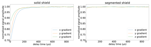
Figure 3 shows the results of the one pulse measurements, with the solid shield shown on the left and segmented shield on the right. With the segmented shield the maximum amplitude decrease is 2%, compared to 29% with the unsegmented shield, measured after a 10 μs delay time.
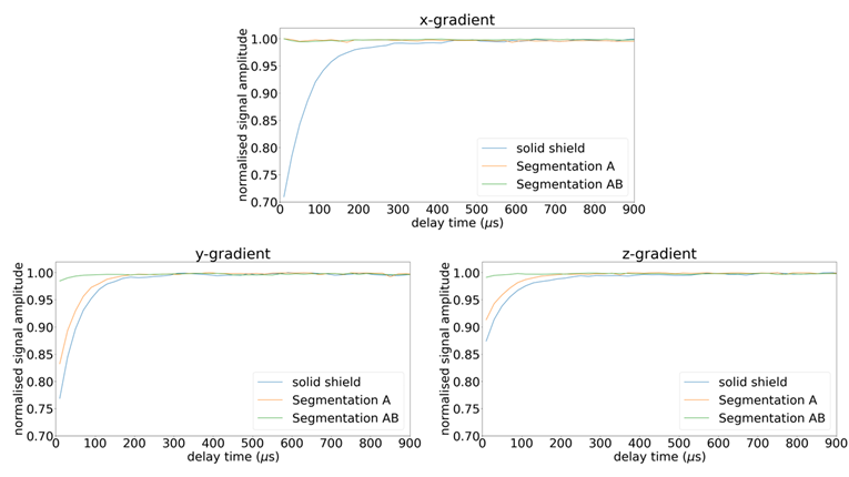
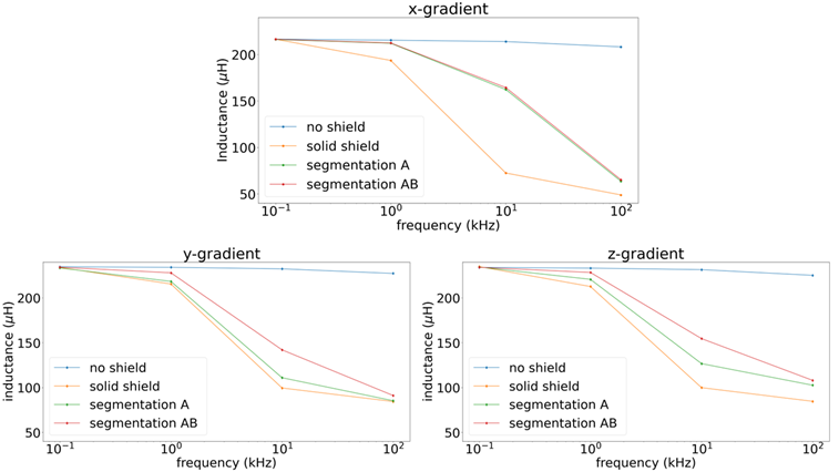
Figure 4 indicates how individual segmentations affect the eddy currents. Segmentation A primarily affects the x-gradient, while B only affects the y- and z-gradients. This is also reflected in Figure 5 showing the inductance measurements, which confirms that the segmentations reduce the mutual inductance of the corresponding coils.
Discussion
This work shows that given the current density maps of the gradient coils a segmented shield can be designed which reduces the measured eddy current effects by a factor of 15 while only 4% additional noise is coupled into the experiment.Acknowledgements
H2020 European Research Council,Grant/Award Number: 101021218References
[1] C. P. BidinostiM. E. Hayden. Selective passive shielding and the Faraday bracelet. Appl. Phys. (2008); 93 (17): 174102. https://doi.org/10.1063/1.2998607
[2] B. J. Lee, R. D. Watkins, C. M. Chang, C. S. Levin. Low eddy current RF shielding enclosure designs for 3T MR applications. Magn Reson Med. (2018);79(3):1745-1752. doi:10.1002/mrm.26766
[3] C. E. Hayes and M. G. Eash. Shield for decoupling RF and gradient coils in an NMR apparatus”. US Patent: 4642569. Feb. 10, 1987
[4] P. B. Roemer and W. A. Edelstein. “RF shield for RF coil contained within gradient coils of NMR imaging device”. US Patent: 4871969. Oct. 3, 1989.
[5] R. Rzedzian and C. Martin, “Split shield for magnetic resonance imaging”. US Patent: 005243286. Sept 7, 1993.
[6] R. Meena, Y. Junqi, T. Liang, et al. (2023). Frequency Selective Surface (FSS) Radiofrequency Shield of Solenoid Coil for Low-Field Portable MRI. TechRxiv. Preprint. https://doi.org/10.36227/techrxiv.24258784.v1
[7] Y. Liu , A.T.L. Leong, Y. Zhao, et al. A low-cost and shielding-free ultra-low-field brain MRI scanner. Nat Commun (2021 Dec); 14;12(1):7238. doi: 10.1038/s41467-021-27317-1
[8] M.S. Poole, C. Hugon, H.A. Dyvorne, et al. Electromagnetic shielding for magnetic resonance imaging methods and apparatus. US Patent: 10274561B2, Apr, 2019.
[9] O'Reilly T, Teeuwisse WM, Webb AG. Three-dimensional MRI in a Homogenous 27 cm Diameter Bore Halbach Array Magnet. J Magn Reson (2019); 307:106578. doi:10.1016/j.jmr.2019.106578
[10] B. , J. , Z. , et al. Design, characterisation and performance of an improved portable and sustainable low-field MRI system. Front Phys (2021); 9. doi:10.3389/fphy.2021.701157
[11] A. Webb, T. O’Reilly. Tackling SNR at Low-Field: A Review of Hardware Approaches for
Point-of-Care Systems. MAGMA (2023); 375–93. https://doi.org/10.1007/s10334-023-01100-3
Figures