4076
Movable Linear Gradients Optimized on Non-Planar B0 Slice Profiles Used for Improving Spatial Encoding in a Non-Linear Low-Field MRI1Department of Biomedical Engineering, Yale University, New Haven, CT, United States, 2Department of Radiology and Biomedical Imaging, Yale School of Medicine, New Haven, CT, United States
Synopsis
Keywords: Low-Field MRI, Low-Field MRI
Motivation: Spatial resolution in an open low-field MRI that uses surface RF coils for B1-encoding can be improved by repositioning the RF coils within FOV for each TR. However, this approach is limited by space constraints in the left-right dimension. Linear gradients, especially movable ones optimized for a slab, effectively supplement encoding in that direction.
Goal(s): To improve spatial resolution in the left-right direction of an open low-field MRI.
Approach: A linear gradient optimized on B0 slice volume is moved in the anterior-posterior direction dependent on readout slice location.
Results: Movable gradients improve spatial encoding.
Impact: There is an unmet need for open low-field MRIs that can accommodate patients of all sizes and disabilities: this approach to generating high spatial resolution images without the use of volume-encompassing gradients makes open MRI viable.
Introduction
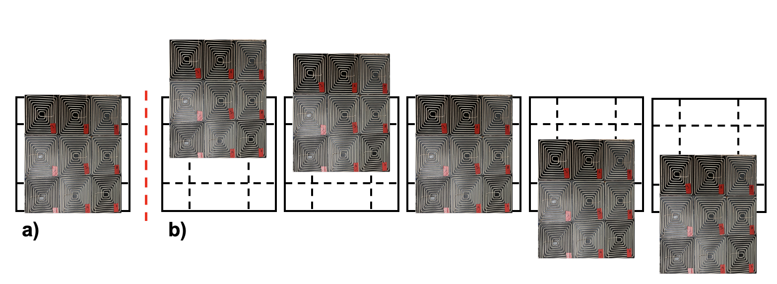
The process of developing low-field MRI provides an opportunity to redesign the traditional constraints on MRI (such as cylindrical and tight bores). To better accommodate chest and torso imaging, we are developing an open MRI (Figure 1a). The lack of volume encompassing gradients means that standard three-gradient encoding methods cannot be used. Instead, we propose to use Bloch-Siegert encoding in which an off-resonance radiofrequency (RF) pulse induces a spatially dependent phase shift to the on-resonance transverse magnetization1. The Bloch-Siegert pulses are transmitted from a 3x3 element planar RF array that lays flat on the surface of the magnet but under the patient (Figure 1a-b). Each element of the planar RF array creates a unique phasor pattern, and the combinations of the different patterns produce different spatial information.To increase the number of unique phasor patterns, stop-motion imaging2 is used. In stop-motion imaging, the RF coil array is moved to a different position within the field-of-view (FOV) for each TR, creating a different point-of-view, with the goal of increasing spatial resolution (Figure 2).
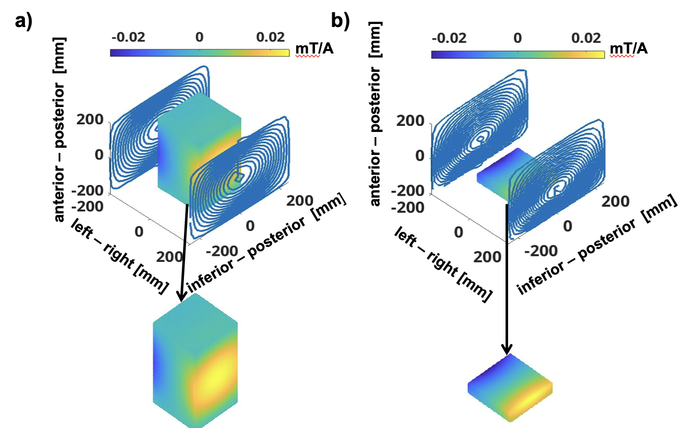
The magnet device is 400mm wide, and the RF coil array is 380mm wide: thus, there is limited room for the coils to be moved in the left-and-right direction, and encoding in the left-right direction is limited. We propose to add a gradient coil whose halves lie along each wing of the magnet to produce a magnetic field that linearly varies from left to right. This increases spatial resolution achievable in the left-right direction while still maintaining the magnet’s openness.
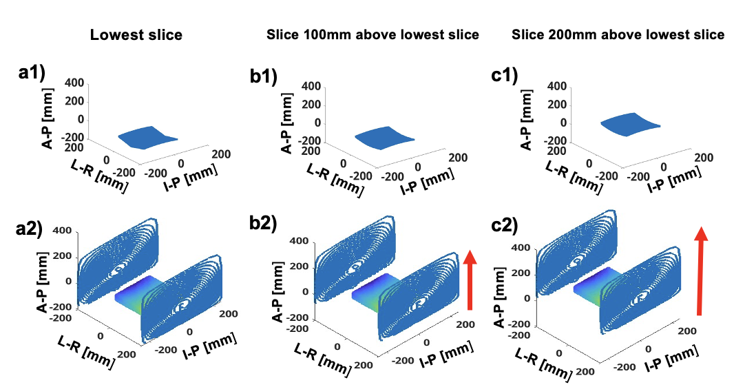
One approach is to design a magnet that produces this gradient across the entire volume of interest (Figure 3a). Alternately, the gradient can be optimized over a narrower extent in the anterior-posterior direction (Figure 3b), and gradient coils can be moved in the anterior-posterior direction to align with each B0 readout slice (Figure 4a2, 4b2, 4c2). The B0 slices are not planar, instead each slice varies in height up to 50mm (Figure 4a1, 4b1, 4c1). Thus, it is necessary to optimize the gradient to create a magnetic field that varies linearly and homogenously across a volume of height 50mm (Figure 3b).
Methods
The stop-motion imaging simulation was performed at fifteen locations: the RF coils are moved in increments of 10mm along a 150mm path in the superior-inferior direction along the magnet’s centerline (Figure 2).The encoding schemes were calculated as the weighted sum of the B1-fields from each channel of the RF coil array with all nine coils in-phase. Bloch simulations were used to calculate the generated phasor at each of the fifteen locations with respect to the locations within the non-linear B0 field.
Gradient coils optimized on a 200x200x400mm FOV (Figure 3a) and on a 200x200x50mm FOV (3b), respectively, were designed with the help of CoilGen software3. Both gradients have maximum 0.25 mT/m/A, inductance 87μH, and resistance 0.46Ω. Gradient fields generated by CoilGen with input current 8Amps were added to the Bloch simulation phasors. The added gradient fields follow the B0 slice shape, capturing the height effects of the non-planar slices. The MR signal created by each encoding scheme at each location was reconstructed using the conjugate gradient method4.
Results
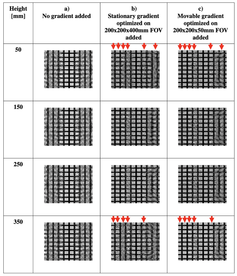
Figure 5a shows the result from reconstructing a grid phantom using stop-motion imaging performed at fifteen locations along a superior-inferior trajectory. Figure 5b shows the result of reconstructing the phantom using stop-motion imaging performed at fifteen locations in conjunction with the stationary gradient optimized over the 200x200x400mm FOV, and 5c shows stop-motion imaging performed at fifteen locations along with the movable gradient optimized on the 200x200x50mm FOV. As shown, using gradients always outperforms stop-motion imaging done with no gradients. The reconstruction performance when using the two types of gradients is similar for the B0 slices in the center of the magnet (150, 250mm). However, in the lower and higher B0 slices (50, 350mm), the movable gradient optimized on a smaller FOV performs better than the stationary gradient optimized on a larger FOV (pointed out by red arrows).Discussion
The results show that adding even a weak gradient to the encoding method improves spatial resolution. Optimizing the gradient on each non-planar slice and moving it coincident with slice selection provides better spatial encoding than a fixed gradient optimized on the imaging volume.Conclusion
The combination of a gradient planar coil and stop-motion imaging with Bloch-Siegert encoding produces high spatial resolution images. The addition of a movable planar gradient that creates an optimized gradient for each slice improves the image quality in an open low-field MRI.Acknowledgements
No acknowledgement found.References
1. Kartäusch, Ralf, et al. "Spatial phase encoding exploiting the Bloch–Siegert shift effect." Magnetic Resonance Materials in Physics, Biology and Medicine 27 (2014): 363-371.
2. Samardzija, Anja, et al. “Stop-Motion RF for Improving Spatial Resolution in Non-Linear Gradient-Free Low-Field MRI.” ISMRM 1761 (2023).
3. Amrein, Philipp, et al. "CoilGen: Open‐source MR coil layout generator." Magnetic Resonance in Medicine 88.3 (2022): 1465-1479.
4. Selvaganesan, Kartiga, et al. “Nonlinear encoding scheme for gradient-free projection imaging in an inhomogeneous B0-magnet.” ISMRM 0504 (2022).
Figures