4075
Open-Source, High-Efficiency, Easily-Reconfigurable Switch-mode Current Driver for B0 Shimming and Local Field Control1Massachusetts Institute of Technology, Cambridge, MA, United States, 2Athinoula A. Martinos Center for Biomedical Imaging, Cambridge, MA, United States, 3Electrical Engineering, Stanford University, Stanford, CA, United States, 4Radiological Sciences Laboratory, Stanford University, Stanford, CA, United States, 5Q Bio, Inc., San Carlos, CA, United States, 6Massachusetts General Hospital, Charlestown, MA, United States, 7Siemens Healthcare, Charlestown, MA, United States
Synopsis
Keywords: New Devices, New Devices
Motivation: Multi-coil arrays have demonstrated utility for higher-order B0 shimming, spatial encoding, and local field control. However, existing amplifiers used to drive these coils typically trade off efficiency and imaging noise.
Goal(s): Demonstrate a proof-of-concept amplifier with both high efficiency and low imaging noise, while being easily reconfigurable for different loads impedances.
Approach: A switch-mode amplifier with highly-integrated power stages, 6th-order LC filtering, and fully-digital control was developed. Its thermal performance, dynamic performance, and impact on imaging noise was tested.
Results: Our amplifier demonstrated heatsink-free 10ADC drive capability, <25μs step response rise-times with multiple loads, acceptable disturbance rejection, all while minimally impacting image quality.
Impact: We have demonstrated an open-source, proof-of-concept amplifier achieving power efficiencies of switch-mode designs while maintaining imaging noise levels akin to linear designs. Such an amplifier unblocks novel spatial encoding techniques and local field control applications. Development is active and ongoing.
Introduction
A growing body of work explores the use of independently-driven multi-coil B0 shim arrays and matrix gradient coils for higher-order B0 shimming, spatial encoding, and other local field-control applications[1–5][6,7]. Drive electronics (referred to as “amplifiers”) for these coil arrays are required to supply regulated positive and negative currents. Additional requirements include (i) minimal impact on imaging noise, (ii) the ability to drive time-varying kHz-range current waveforms, (iii) ability to reject disturbance from scanner gradient coil slewing. Low cost, scalability to high channel-counts, and ease of use are additional design targets.Linear amplifier topologies (e.g., Class-AB) provide the benefit of a low noise floor and low implementation cost[8]. When driving low-resistance loads or higher currents, however, efficiency and thermal management challenges limit their usage. To provide more flexibility for encoding applications requiring high currents (>5A)[9,10][11][2], more efficient switch-mode “Class-D” amplifiers have been proposed[12,13]. However, switching harmonics produced by these designs can potentially lead to image artifacts.
In this work we demonstrate an amplifier matching the efficiency of a switch-mode design, in-band noise levels approaching those of a linear design, and ease-of-configuration simpler than either design. This is achieved through the careful design of the power path and experimentation with fully-digital control.
Circuit board design files, embedded device firmware, and host interface software of our design are released under open-source licenses.
Methods
Power Path: CSD95372AQ5M integrated power stages from Texas Instruments were chosen as the main power devices for the Class-D amplifier. Outputs from the power stage were passed through a 6th-order LC filter. Aside from any nickel plating on terminals, all components of the design were non-magnetic. Aside from the circuit board substrate, no heat-sinking was used for the design.Output Current Control: Control was implemented fully digitally on an STM32G474RE[14] microcontroller (MCU), allowing for automatic computation of control constants, given user-provided load parameters and operating frequencies. Output drive current was measured using a shunt resistor, INA241A1[15] amplifier, and an MCU analog-to-digital converter channel. Power stage pulse-width modulation signals were synthesized by the MCU at a user-selectable frequency from 1-2MHz. Commands and configuration information were entered by the user into a simple PC application and sent to the MCU.
Bench Testing: The amplifier’s thermal performance driving DC current into a 200mΩ load was measured. Additionally, the controller’s step responses driving three different loads using firmware-computed control constants was characterized.
Scanner Testing: Disturbance rejection and imaging noise tests were conducting using a Siemens Skyra 3T scanner. The current driver was connected to a single channel of a combination RF/B0-shim head coil with a coaxial cable leading outside the scanner room. Impedance of the coil and cable assembly were entered into the MCU and control constants automatically computed. Drive current disturbance rejection of the driver was measured by measuring the deviation from a driven target current during an EPI sequence with transmit disabled. This was then compared to the current magnitudes induced into a shorted coil. In-band spectral noise produced by the amplifier driving a DC current was measured with the scanner’s “rf_spectrum” service tool. This was compared to spectral noise produced by a linear power supply (Tektronix PWS2326). To qualify imaging noise, a phantom was imaged using a GRE pulse sequence with transmit voltage both disabled and enabled. B0 maps were also generated to measure shimming performance. Images and field maps produced by the switch-mode driver and the linear supply were compared.
Results
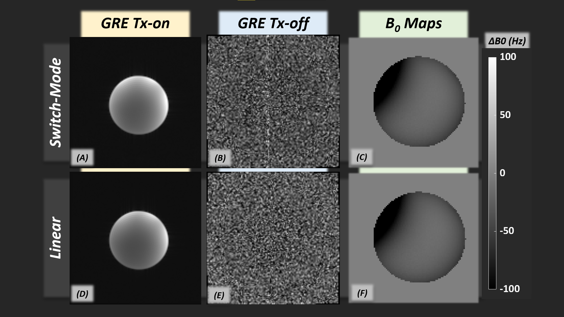
When driving 5A and 10A DC, peak temperatures on the board were measured at 46°C and 71°C respectively (Fig. 2). 10-90% rise time between the commanded initial and final current values measured less than 25 microseconds for all the loads tested (Fig. 3a). During disturbances by gradient slewing, drive current deviated from the setpoint by 13.4mA RMS, a factor of 3.1 improvement over an unregulated coil (Fig. 3b). Figure 4 compares the impact of the switch-mode amplifier on the scanner noise floor to that of a linear supply. Figure 5 compares images acquired and B0 maps generated using the switch-mode amplifier and a linear drive.Discussion & Conclusion
We demonstrate a device capable of efficiently driving 10A time-varying currents with minimal impact on imaging noise. The simplified control-loop tuning experience lets researchers quickly and confidently configure complex coil arrays, with control loops tailored to their particular coil parameters.Future experiments will explore the efficacy of an analog implementation of the controller, anticipated to improve imaging noise, control bandwidth, disturbance rejection, and feasibility of in-bore operation. Such improvements will further enable many local field-control applications.
Design file links:
Hardware: https://github.com/Govish/Shimamp-Hardware
Firmware: https://github.com/Govish/ShimAmp-Firmware
Host Software: https://github.com/Govish/ShimAmp-Host-Software
Acknowledgements
This work was supported by the NIH [grant numbers U24EB028984, R00EB021349, R01EB028797]. The authors would additionally like to thank Prof. David J. Perreault (Massachusetts Institute of Technology) for help in assessing the feasibility of the concept, as well as Mike Twieg (Hyperfine Research) for design insight.References
- Juchem C, Nixon TW, McIntyre S, Boer VO, Rothman DL, De Graaf RA, 2011. Dynamic multi-coil shimming of the human brain at 7 T. J Magn Reson. 212(2):280-288. PMID: 21824794.
- Umesh Rudrapatna S, Fluerenbrock F, Nixon TW, de Graaf RA, Juchem C, 2019. Combined imaging and shimming with the dynamic multi-coil technique. Magn Reson Med. PMID: 30303553.
- Scheffler K, Loktyushin A, Bause J, Aghaeifar A, Steffen T, Schölkopf B, 2019. Spread-spectrum magnetic resonance imaging. Magn Reson Med. 82(3):877-885.
- Han H, Song AW, Truong T-K, 2013. Integrated Parallel Reception, Excitation, and Shimming (iPRES). In: Int. Soc. Magn. Res. Med. ; 2013:664.
- Stockmann JP, Witzel T, Keil B, Polimeni JR, Mareyam A, Lapierre C, Setsompop K, Wald LL, 2016. A 32-channel combined RF and B0 shim array for 3T brain imaging. Magn Reson Med. 75(1).
- Umesh Rudrapatna S, Juchem C, Nixon TW, de Graaf RA, 2016. Dynamic multi-coil tailored excitation for transmit B1 correction at 7 Tesla. Magn Reson Med. 76(1):83-93. PMID: 26223503.
- Stockmann J, Arango NS, Poser B, Witzel T, White J, Wald LL, Jonathan R, 2018. Spatially-selective excitation using a tailored nonlinear ΔB0 pattern generated by an integrated multi-coil ΔB0/Rx array. In: Int. Soc. Magn. Res. Med. ; 2018:170.
- Arango N, Stockmann JP, Witzel T, Wald L, White J, 2016. Open-source, low-cost, flexible, current feedback-controlled driver circuit for local B0 shim coils and other applications. Proc Intl Soc Mag Reson Med 24.:1157.
- Puy G, Marques JP, Gruetter R, Thiran J, Member S, De D Van, Vandergheynst P, Wiaux Y, 2011. Spread spectrum magnetic resonance imaging. (c):1-13.
- Xu J, Stockmann J, Bilgic B, Witzel T, Cho J, Liao C, Zhang Z, Liu H, Setsompop K, 2020. Multi-frequency wave-encoding (mf-wave) on gradients and multi-coil shim-array hardware for highly accelerated acquisition. In: Int. Soc. Magn. Res. Med. 28th Annual Meeting. ; 2020:618.
- Zhang M, Arango N, Stockmann JP, White J, Adalsteinsson E, 2022. Selective RF excitation designs enabled by time-varying spatially non-linear ΔB0 fields with applications in fetal MRI. Magn Reson Med. 87(5):2161-2177. PMID: 34931714.
- Yu H, Littin S, Jia F, Stefan K, and Maxim Z. Single H-Bridge Shimming Driver. Proc. of the Int. Soc. Magn. Res. Med. 2019, p. 1469.
- Twieg M, Griswold MA In-Bore High Efficiency Current Driver. Proc. of the Int. Soc. Magn. Res. Med. 2017, p. 2708.
- STMicroelectronics N.V.; Geneva, Switzerland
- Texas Instruments Incorporated; Dallas, Texas
Figures
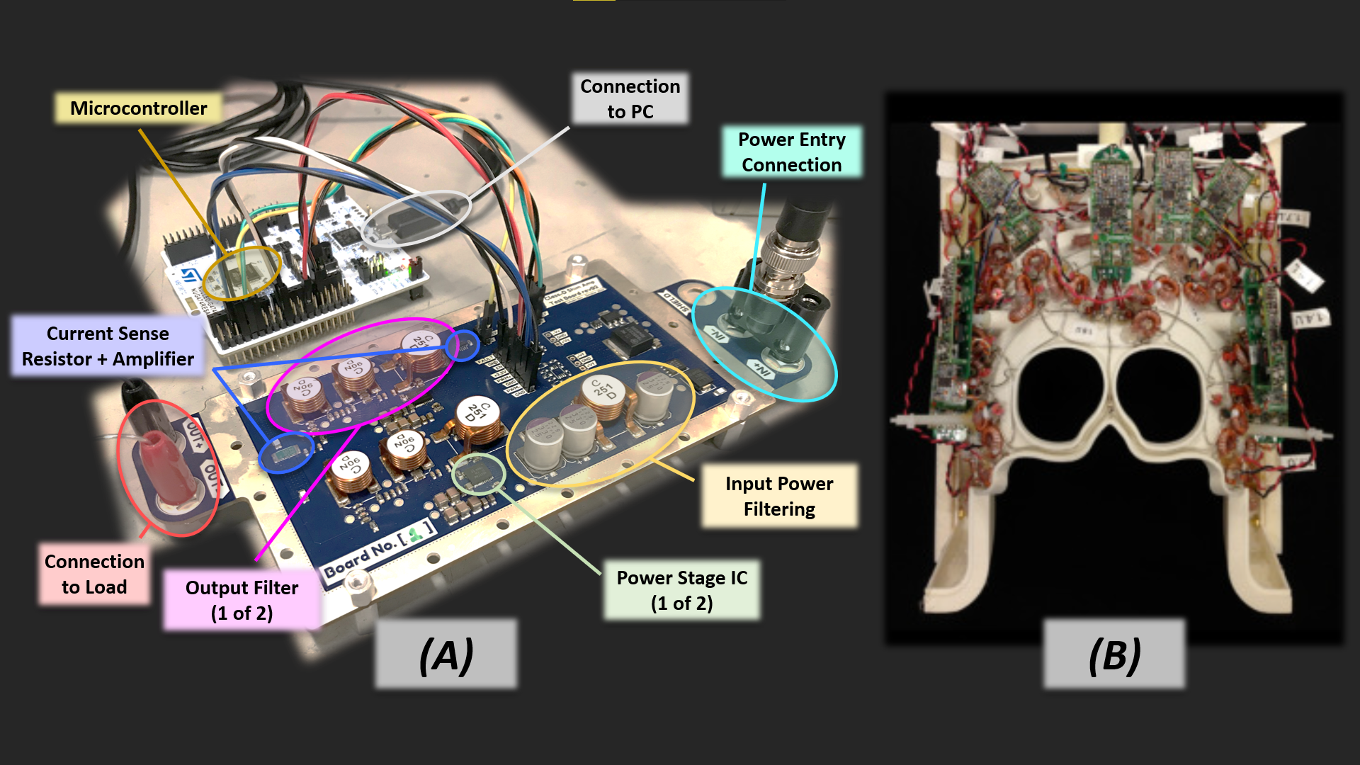
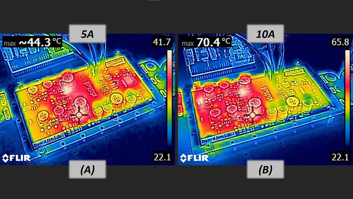
Figure 2. Thermal images showing temperature rise of the amplifier driving a 200mΩ load at (a) 5ADC, and (b) 10ADC. Ambient temperature during the tests was 22°C; amplifier supplied with 12V and switched at 1.5MHz. Temperatures shown are with natural convection with no heatsinks other than the circuit board substrate. Note that in both the board temperature is 15-20°C less than the peak recorded temperatures.
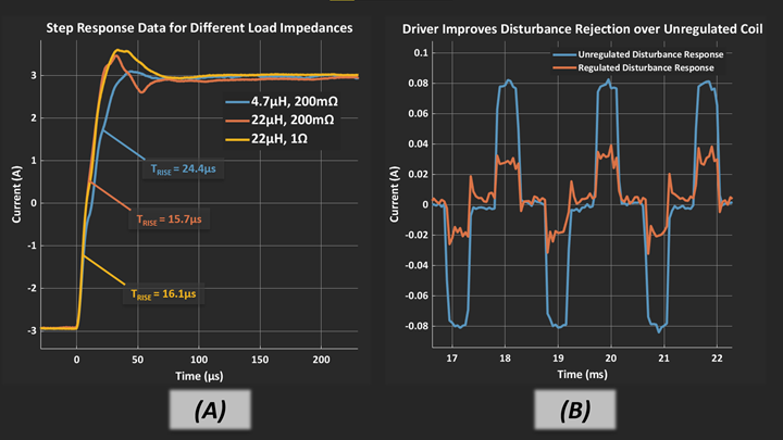
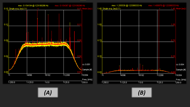
Figure 4. Noise-floor of the receive chain across a 500kHz-wide imaging band. Noise floor was measured using the scanner ‘rf_spectrum’ service tool. (a) shows the noise floor when driving a single channel of a combination RF/B0-shim head coil with 2ADC sourced by a linear power supply. (b) shows the noise floor when driving the same channel with 2ADC sourced by the switch-mode amplifier operating at 12VDC and 1.25MHz. Notice the rescaling of the Y-axis. Also notice that the spectrum is dominated by a single narrow-band spur, with the noise floor being otherwise similar to the linear case.