3943
Reproducible B0 shim matrix calibration at 7T and dynamic range analysis of spherical harmonics for residual compensation
1Molecular and Cellular Imaging, Comprehensive Heart Failure Center, University Hospital Würzburg, Würzburg, Germany, 2Institute of Nuclear Techniques, Budapest University of Technology and Economics, Budapest, Hungary, 3Departments of Biomedical Engineering, Columbia University, New York, NY, United States, 4Department of Psychiatry, Psychosomatics, and Psychotherapy, University of Würzburg, Würzburg, Germany, 5Department of Psychology, University of Würzburg, Würzburg, Germany
Synopsis
Keywords: High-Field MRI, Shims
Motivation: Adequate B0 shimming of deep brain regions at 7T using 3rd order shims.
Goal(s): Reproduce B0 shim matrix calibration after hardware replacement and estimate possible compensation of residual fields in vivo.
Approach: Calibration matrix of the 3rd order B0 shimming system was measured after replacement of the gradient coil. Results were compared with previous calibration. Whole-brain and ROI-specific spherical harmonic decompositions of B0 maps were performed after optimized whole-brain shimming.
Results: Shimming calibration matrices could be reproduced with high accuracy on the new hardware. Residual B0 inhomogeneity could potentially be improved with existing shimming hardware.
Impact: B0 shimmming calibration matrix is well reproducible on a 7T system equipped with 3rd order shim coils using single and multi-channel receiver coil configurations. Residual B0 inhomogeneity after optimized whole-brain shimming could be potentially improved using available shimming hardware.
Introduction
Ensuring adequate B0 field homogeneity of ultra high field (UHF ≥ 7T) human MRI scanners remains a challenge, limiting applications in numerous anatomical regions of the brain, even with vendor-provided 3rd order shim coil systems.Here, we report on the reproducibility of B0 shim matrix calibration of a 7T system equipped with 3rd order shim coils after the gradient and shim system replacement using single channel and multi-channel TX/RX coils. Whole-brain and ROI-specific B0 reconstruction and spherical harmonic (SH) decomposition were performed after whole-brain shimming. The goal was to estimate the potential for further improvement of B0 field homogeneity in deep brain regions.
Methods
1. Recalibration of the shim system: All measurements were performed on a Siemens MAGNETOMTM Terra 7T. The multi-echo gradient echo (ME-GRE) fieldmap sequence was measured on an oil phantom using a 1TX/2RX Siemens TuneUp coil (Siemens Healthineers, Erlangen, Germany) with a high resolution (HighRes) and a low resolution (LowRes) protocol. The parameters of the HighRes are as follows: TE1/TE2/TE3/TE4/TE5 = 1/3/5/7/9 ms, TR = 30 ms, FA = 19°, orientation = TRA, PE = RL, nominal resolution = 1.7 x 1.7 x 1.7 mm3, FOV = 220 x 192.5 x 176.8 mm3, enforcing symmetric echo and monopolar RO gradient scheme. For the LowRes sequence settings the nominal resolution = 2.8 x 2.8 x 2.8 mm3. During calibration, the currents of controlling components of the linear SH terms were changed in 7 equidistant steps within ±10% of the full dynamic range and were increased up to ±30% for the second and third order SH components . All phase images were unwrapped and the B0 field map was computed within the masked area defined by the magnitude images using the ROMEO toolbox1. Magnetic field decomposition of the B0 maps into SH was performed by the custom B0DETOX software2,3 , while linear curve fitting was performed in MATLAB 2022a (The MathWorks Inc., Natick, MA, USA).2. Reproducibility of specific SH components with multi-coil array: Replicated measurements of the previous section were executed only on Z, Z2 and Z3 SH components using the 1TX/32RX Nova head coil (Nova Medical,Inc., MA, USA). Phase and magnitude images were saved prior to and after system coil combination as well, twix and DICOM, respectively, enabling offline signal-to-noise-ratio (SNR) optimal coil combination of multi-channel data that reflect only ΔB0-related phase using the MCPC-3D-S toolbox4.
3. In vivo brain shim performance: A ME-GRE fieldmap sequence was measured in vivo with the following parameters: TE1/TE2/TE3/TE4/TE5 = 1.5/4.01/6.52/9.03/11.54 ms, TR = 15 ms, FA = 8°, orientation = TRA, PE = RL, resolution = 3 x 3 x 3 mm3. The adjustment volume incorporated the whole brain. Only a single well-shimmed measurement was obtained using the Nova coil, powered by a Siemens Work-In-Progress algorithm (WIP 1441, original version)5. Evaluation was performed with the same methodology, thus decomposing into all SH components. For the limited SH decomposition, the B0DETOX software was informed that three 3rd order terms (X3, ZXY and Y3) are not implemented in the 3rd order shim electronics.
Results
The shim system was successfully recalibrated, and the new covariance matrix shows less than 5% difference in self-terms compared to the previous calibration (Figure 1). Cross-term contaminations are dominant only between odd order shims (1st and 3rd).Multi-coil receiver arrays manifest singularities in the DICOM phase maps (Figure 2), in contrast to SNR-optimal offline coil combination. Regardless of the method, all self-terms are in close agreement.
Reconstructed B0 maps, fitted SH and residual fields for the whole brain and the ROI-specific deep brain region are displayed on Figure 3 and Figure 4, respectively. The axial whole brain slice of the residuals clearly shows the absence of the physical X3 term.
Figure 5 shows the summary of the fitted SH components for all cases. All SH components fall within the physically feasible dynamic range, thus leaving room for the compensation of B0 field residual inhomogeneity by fine tuning the shimming algorithm.
Discussion & Conclusion
Recalibration fidelity suggests that an update of the shim calibration matrix may be necessary for systems equipped with 3rd order shim coils after hardware replacement. The highest cross-term contamination is manifested between the 1st and 3rd order components, suggesting a parity-dependent coupling of SH. SNR-optimal coil combination results in a better estimation of the ΔB0-related phase, but such a small number of singular pixels does not corrupt the SH decomposition. The application of the WIP 1441 shimming package potentially leaves room for further compensation of residual B0 inhomogeneities with dynamic linear order shimming and fine-tuning shimming algorithms for the higher order terms.Acknowledgements
Financial support was granted by IZKF Projekt F-461 (Hein/Gamer/Terekhov) “High-resolution structural and functional imaging of the brain to investigate subcortical structures”.
References
1. Dymerska, B., Eckstein, K., Bachrata, B., Siow, B., Trattnig, S., Shmueli, K., Robinson, S.D., 2020. Phase Unwrapping with a Rapid Opensource Minimum Spanning TreE AlgOrithm (ROMEO). Magnetic Resonance in Medicine.
2. Juchem C, Rudrapatna SU, Nixon TW, de Graaf RA. Dynamic multi-coil technique (DYNAMITE) shimming for echo-planar imaging of the human brain at 7 Tesla. NeuroImage. 2015;105:462-472.
3. Juchem C. B0DETOX—B0 Detoxification Software for Magnetic Field Shimming. innov ation.colum bia.edu/techn ologi es/cu173 26_b0detox. 2017. Columbia Tech Venture, license CU17326. Accessed July 8, 2020.
4. Eckstein, K., Dymerska, B., Bachrata, B., Bogner, W., Poljanc, K., Trattnig, S., Robinson, S.D., 2018. Computationally Efficient Combination of Multi-channel Phase Data From Multi-echo Acquisitions (ASPIRE). Magnetic Resonance in Medicine 79, 2996–3006.
5. S. Nassirpour, P. Chang, A. Fillmer, and A. Henning, “A comparison of optimization algorithms for localized in vivo B0 shimming,” Magn. Reson. Med., 2017, doi: 10.1002/mrm.26758.
Figures
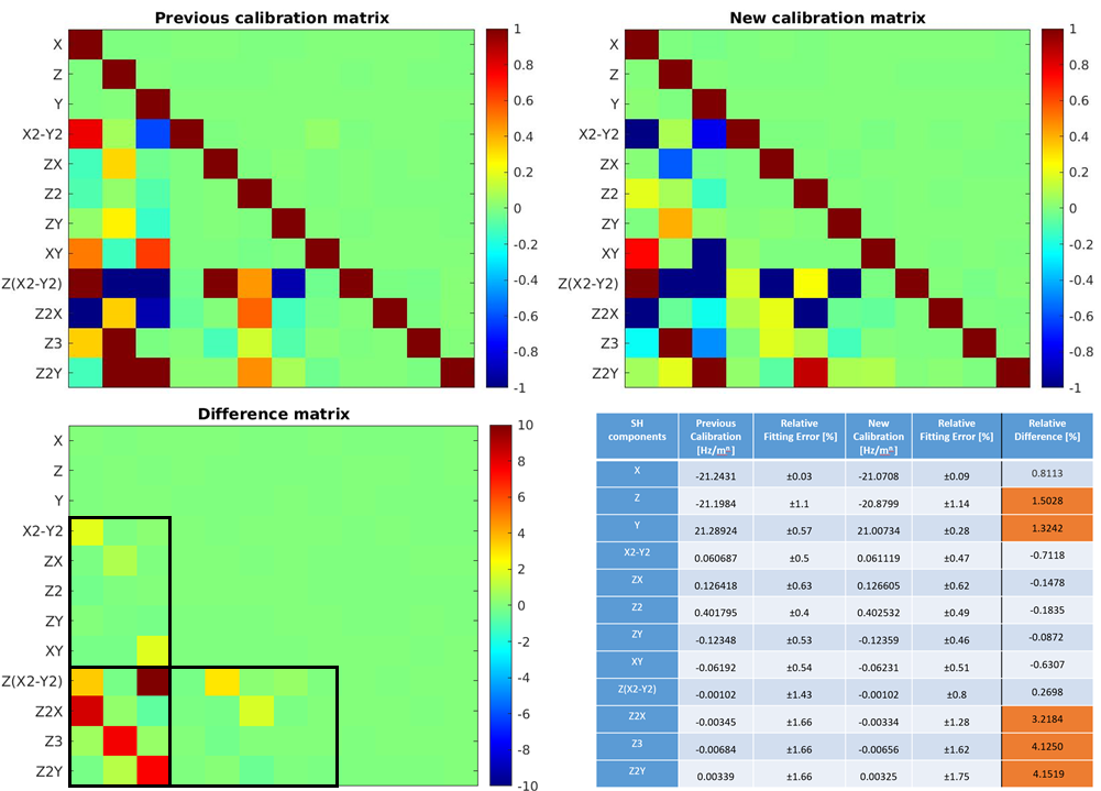
Figure 1. The previous and the new shim calibration matrices are plotted in the top row. The difference matrix of the two covariance matrices is computed in the bottom row. Black rectangles indicate the 1st–2nd order, 1st–3rd order and 2nd–3rd order cross terms that manifest significant contamination. The highest contamination is manifested between the 1st and 3rd order tems. The diagonal elements (self-terms), the relative fitting error and the percentage difference of the two measurments are listed in the bottom table. SH components differing by more than 1% are highlighted orange.
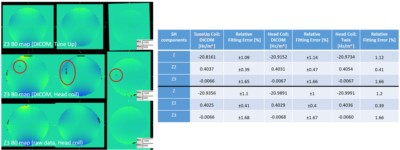
Figure 2. Representative example of the HighRes Z3 SH component measured on the same phantom with different coils (TuneUp vs. NovaHead) (left). Fieldmaps calculated from DICOMs manifest singularities (highlighted in red) due to insufficient receiver phase combination. SNR-optimal offline combination omits all singularities in the volume. The examined self-terms remain in close agreement (right), regardless of the acquisition setup (Highres vs. LowRes, TuneUp vs. NovaHead) and of coil combination (system DICOM vs. offline twix). Note that n in Hz/mn designates the SH order.
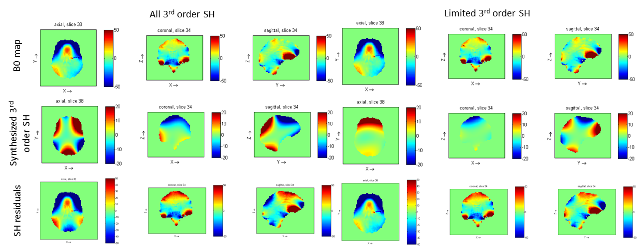
Figure 3. Representative whole brain slices of reconstructed B0 fieldmaps (top row), synthesized SH components (middle row) and residual fields (bottom row). The limited 3rd order SH decomposition (right column), a.k.a. projection onto the physically implemented coils, clearly shows the absence of the X3 term on the axial residual slice, when compared to the decomposition to full 3rd order SH (left column).
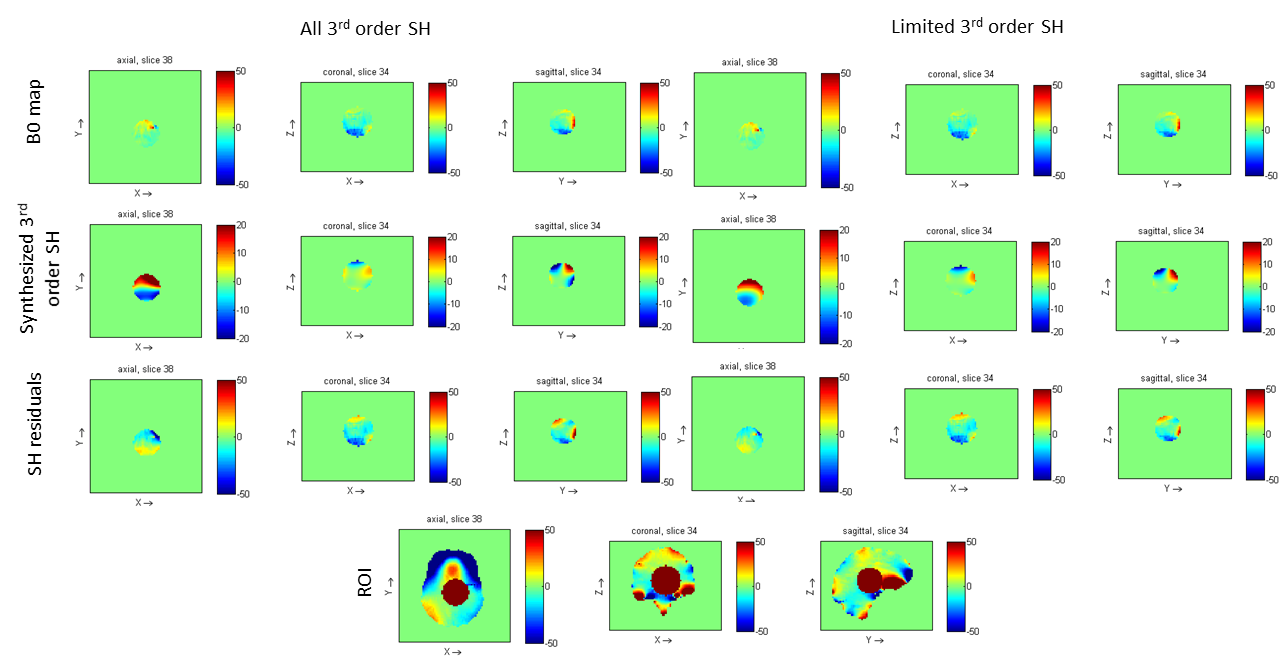
Figure 4. Representative deep brain slices of reconstructed B0 fieldmap (top row), synthesized SH components (middle row) and residual fields (bottom row). The full 3rd order decomposition (left column) shows linear residuals on the axial slices, in contrast to the limited 3rd order decomposition, which would leave room for dynamic shimming during sequence playout with the gradient system. The masked area is overlayed on the whole brain B0 map at the bottom.
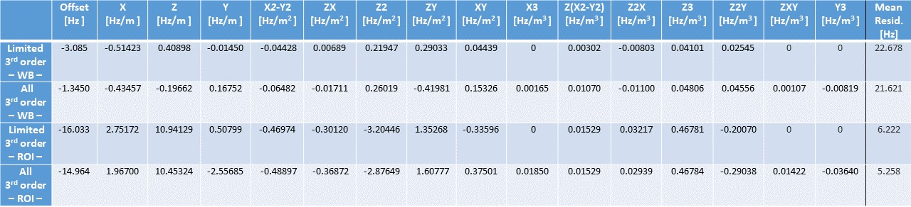
Figure 5. SH decomposition and mean residual field for all cases. The first culomn denotes the components of the SH decomposition, thus offset, X, Z, Y, X2-Y2, ZX, Z2, ZY, XY, Z(X2-Y2), Z2X, Z3, Z2Y for limited 3rd order and the additionally included X3, ZXY, Y3 for all 3rd order. All SH components fall within the physically feasible dynamic range, thus leaving room for B0 field compensation. The physically implemented 3rd order shim coils have the largest contribution among all 3rd order SH, justifying the choice of coil implementations in a limited space.