3938
Measurements of the gradient-induced power deposition in the He-bath of the Iseult 11.7T magnet and comparison with theory1NeuroSpin, CEA, Gif sur Yvette, France, 2Irfu, CEA, Gif sur Yvette, France
Synopsis
Keywords: Magnets (B0), Magnets (B0)
Motivation: Experimental characterization and understanding of the power deposition in the He bath of an ultra-high field magnet is important for magnet safety.
Goal(s): We report a quasi-analytical model for the Z gradient axis power deposition and compare it with measurements.
Approach: The model was based on three cylinders consisting of the He vessel, the cryoshield and the outer vacuum chamber. Coupled partial differential equations involving both electromagnetism and elasticity were derived and solved.
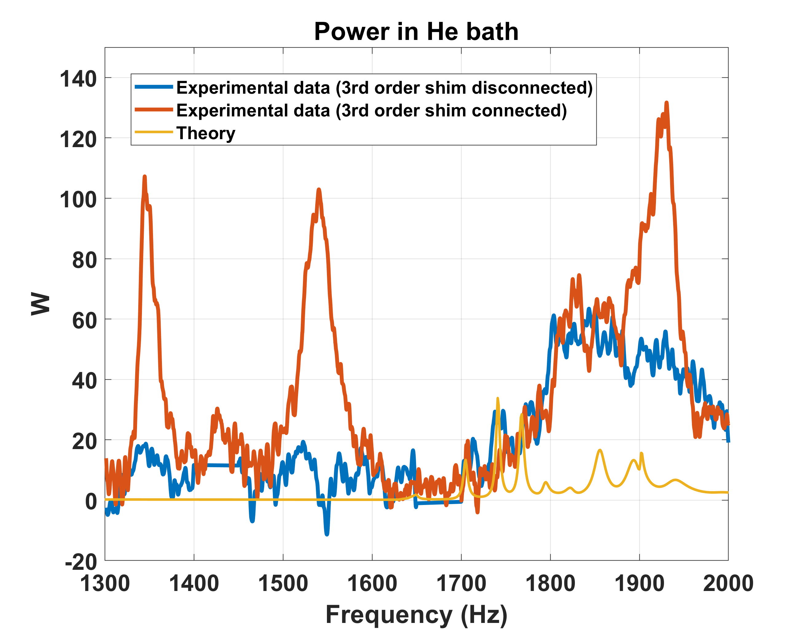
Results: Our model predicts accurately the positions of the cryogenic peaks but underestimates by about a factor of 2-3 the largest ones.
Impact: When the symmetry and underlying assumptions are met, the model allows determining the location of the resonance peaks and can alert the user of potential dangerous frequency zones where caution during first experiments should be exercised.
Introduction
Gradient-magnet interactions increase with stronger field magnets and gradient coils1,2. Perhaps the most sensitive aspect is magnet quench, which can be induced by a loss of superconductivity of the main coil caused by a rise of the temperature of the He bath with gradient activity. Predicting power depositions therefore can be a very valuable tool to avoid dangerous frequency zones but also eventually correct design flaws. In this work, we report model predictions compared to measurements of power deposition in the He bath of the Iseult 11.7T magnet for the Z gradient coil axis.Methods
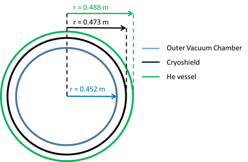
The model consisted of three cylinders (OVC, cryoshield and He vessel) shown in Figure 1. The perturbations arise from the magnetic field generated by the SC72 gradient coil (maximum gradient strength=80mT/m, maximum slew rate=200mT/m/ms), commercialized by Siemens Healthineers, which from the magnetic potential vector $$$\overrightarrow{A_G}(\overrightarrow{r},t)$$$ generates an electric field $$$\overrightarrow{E}(\overrightarrow{r},t)=-\frac{\partial \overrightarrow{A_G}(r,t)}{\partial t}$$$. The $$$\overrightarrow{A_G}(\overrightarrow{r},t)$$$ vector distribution was calculated analytically from the Z gradient coil wire patterns provided by the coil manufacturer. The model incorporates magneto-mechanical physics for which the vibrations of the different elements are described by using the theory of linear elasticity. Eddy-currents are generated from these vibrations which provide electromagnetic coupling between the different tubes. Using the theory of thin shells3, one can derive the following coupled partial differential equations for each cylinder:$$\overrightarrow{j}=\sigma(-\frac{\partial A}{\partial t}+\overrightarrow{V}\times\overrightarrow{B}),$$
$$\rho(\frac{d^{2}\overrightarrow{\delta}}{\text{d}t^{2}}+\omega_{0}^2\overline{\overline{D}}\overrightarrow{\delta})=\overline{\overrightarrow{j}\times\overrightarrow{B}},$$
where $$$\omega_{0}=\frac{1}{a}\sqrt{\frac{E}{\rho(1-\nu^{2})}}$$$ is the fundamental frequency (E is the Young modulus, ρ the mass density, ν the Poisson ratio and a the radius of the cylinder) and $$$\overline{\overline{D}}$$$ contains the Donnell-Mushtari differential operator3. Other variables include: current density $$$\overrightarrow{j}$$$, displacement $$$\overrightarrow{\delta}$$$ (radial δr and axial δz components) while $$$\overrightarrow{V}$$$ is the velocity vector of the element. Calculations were run at fixed frequencies (every 1 Hz) which yield for the PDEs and each value of angular frequency ω:$$\overrightarrow{j}=-i\omega\sigma(A_G+\widehat{A'}+B_{0z}\widehat{\delta_{r}}-B_{0r}\widehat{\delta_{z}}),$$
$$(-\frac{\omega^{2}}{\omega_0^{2}}+\overline{\overline{D}})\left(\begin{array}{c}\widehat{\delta_{r}}\\ \widehat{\delta_{z}}\end{array}\right)=\frac{1}{\rho \omega_{0}^2}\left(\begin{array}{c}\overline{B_{0z}\widehat{j}}\\ -\overline{B_{0r}\widehat{j}}\end{array}\right)$$
where the vector potential $$$\overrightarrow{A'}$$$ comes from the eddy currents engendered by the motional electric field due to vibrations of the conductors. Hats over the variables denote phasors and a bar indicates an average over the thickness of each cylinder. Each tube was discretized by toroids of rectangular cross section (8 and 1 mm length and width respectively) with uniform current density. Given the mechanical boundary conditions, displacements could be described with Fourier series, truncated here with 100 terms for each tube. The coupled partial differential equations thereby became algebraic equations that we solved by using optimized routines in Fortran. Power deposition was then obtained by integrating $$$\frac{|\overrightarrow{j}(r,t)|^{2}}{2\sigma}$$$ within the He vessel. Measurements were performed on the Iseult magnet at 11.7T between 1300 and 2000 Hz, where peaks had been previously located, using a procedure described in1. After noticing their influence, measurements were carried out with and without the 3rd order shim coils connected to the shim filters located inside the Faraday cage.
Results
The power deposition spectra are reported in Figure 2. They were renormalized to the maximum gradient amplitude compatible with maximum slew rate, assuming quadratic dependence of the power versus gradient amplitude. Setting B0 = 0 in the theoretical calculations resulted in power depositions on the order of tens of mW, stressing the importance of taking vibrations into account.Discussion
Our model predicted the main peak positions in the He boil-off spectrum, with 3rd order shim coils disconnected, but underestimated them by a factor of roughly 2-3 for the most intense ones. One weakness of our model remains the mechanical coupling between the different shells, which is not taken into account, and as a result the mechanical resonance modes of the gradient tube. The power deposition into the He bath was measured to be drastically different when 3rd order shim coils were connected, which indicates more complex interactions with these coils when current can flow through them. The latter should thus also be taken into account when they are used during MR operation.Conclusion
We have reported a model describing power deposition generated by the gradient Z axis, believed to be the most problematic, in the He bath of the Iseult magnet. Other axes cannot be modeled equally because of lack of symmetry. Future work includes incorporating mechanical resonances of the gradient coil and mechanical coupling between the different shells. Given the 15W of cooling power of the Iseult cryo-facility, the 200 W.h safety buffer enabled by the large enthalpy of the He reservoir, and the fact that the above measurements versus frequency were for 100% duty cycle, the Iseult magnet is not under threat under normal MR operations with the SC72 gradient coil.Acknowledgements
AROMA H2020 FET-Open (885876).References
[1] Boulant N, Quettier L et al. Commissioning of the Iseult CEA 11.7 T whole-body MRI: current status, gradient-magnet interaction tests and first imaging experience. MAGMA 2023 Apr;36(2):175-189. doi: 10.1007/s10334-023-01063-5.
[2] Winkler S.A, Schmitt F, Landes H, DeBever J, Wade T, Alejski A, Rutt B.K. Gradient and shim technologies for ultra-high field MRI. NeuroImage 2018;168:59-70.
[3] Leissa AW. Vibrations of Shells. NASA, 1973, Acoustical Society of America, 1993.
Figures