3935
Head-Only Z-gradient Array Coil: Induced Electric Field Analysis of 2- and 3-layer Designs1Department of Electrical and Electronics Engineering, Bilkent University, Ankara, Turkey, 2National Magnetic Resonance Research Center (UMRAM), Bilkent University, Ankara, Turkey
Synopsis
Keywords: Safety, Safety, Peripheral Nerve Stimulation, Gradient Array
Motivation: High-performance gradient coils are markedly restricted by peripheral nerve stimulation rather than hardware limitations.
Goal(s): We aimed to reduce the gradient-induced electric fields on the body and consequently increase peripheral nerve stimulation thresholds.
Approach: We introduce a head-only Z-gradient array coil and optimize current weightings of the array configuration to minimize induced electric fields while generating the target gradient within a customizable region with flexible linearity levels.
Results: Utilizing the array configuration reduces the maximum electric field up to 50%, 61%, and 78% compared to a conventional mode for a 22cm spherical region, the disk-shape region at the center, and off-center disks, respectively.
Impact: Peripheral nerve stimulation thresholds of head gradient coils can be increased using array technology; thus, higher gradient strengths and slew rates can be achieved without causing PNS.
Introduction
Rapid switching of strong magnetic fields (B-fields) induces electric fields (E-fields) within the human body, which can potentially trigger nerve stimulation. Several specialized head gradient coils1-3 have been developed to enhance gradient coils performance without causing peripheral nerve stimulation (PNS). In recently introduced Impulse gradient coil1, an additional third layer has been incorporated into the coil design to reduce E-fields (increasing PNS thresholds). It has previously been demonstrated that gradient arrays can similarly lower E-fields by optimizing the driving currents4,5 and offer the flexibility to customize design parameters even after coil fabrication. In this study, we present a head-only Z-gradient array coil, featuring both 2-layer and 3-layer structures and demonstrate their effectiveness in reducing E-fields.Methods
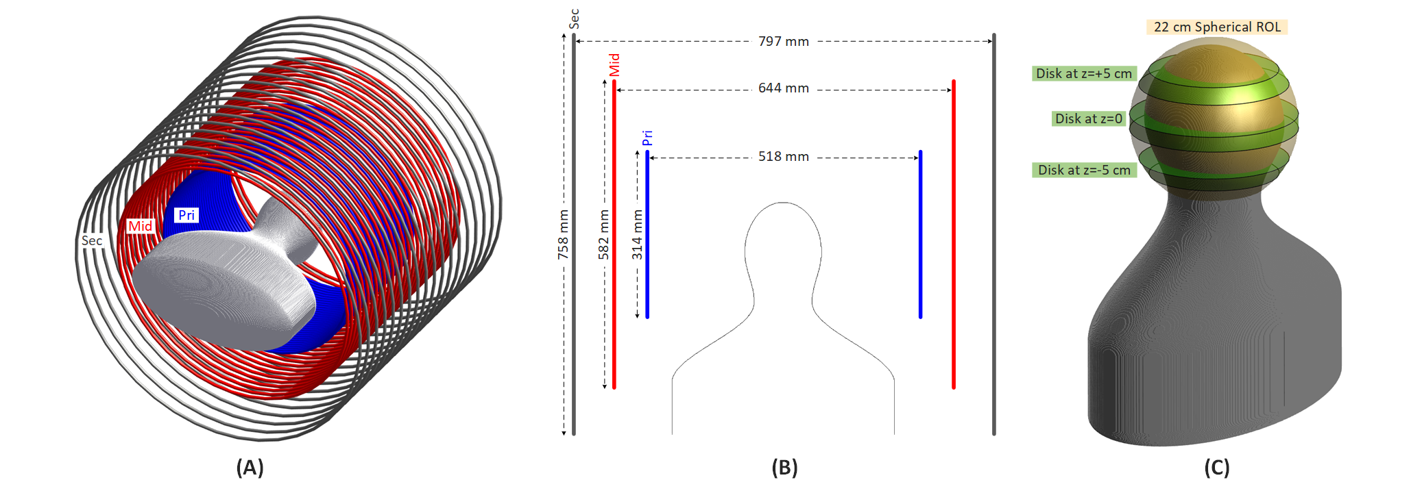
The structure of head-only Z-gradient array is shown in Fig.1. The primary and secondary layers consist of 32 and 18 channels (uniformly distributed circular loops along the z-axis), respectively. The additional mid-layer, has 28 channels. The coil dimensions are chosen to be similar to the Impulse gradient coil. In the current study, we use a simplified body model (homogeneous) representing the 50th percentile male adult population6.In the context of array configurations, the multiple number of channels are considered as basis functions with a predefined pattern but unknown current amplitudes, represented by a vector $$$I={\left[{\begin{array}{*{20}{c}}{{i_1}}&{{i_2}}&{...}&{{i_m}}\end{array}}\right]^T}$$$, where m signifies the number of channels. An optimization problem (Eq. 1) is formulated as determining current amplitudes that minimize the |E|max on the surface of the body model while satisfying a set of constraints. The constraints are placed on the gradient linearity error at specific points across the target region of linearity (ROL), the maximum tolerable magnetic field at the cryostat (a cylindrical shell in the z-direction with 92 cm diameter), the maximum current that hardware can deliver. Prior to optimization, a series of precomputations are conducted to assess the influence of each channel on design metrics. This is achieved by applying a 1 kHz sinusoidal current waveform (1 A amplitude) to a specific channel while keeping the others at zero.
$$\begin{array}{l}\,\,\,\,\,\,\,\,\,\,\,\,\,\,\,\,\,\min\limits_I\,\,\,\,\,\max({\left|E\right|})\\\\s.t.\,\,\,\,{{{\left|{{{\bf{G}}}I-{g_{target}}}\right|}}}\le\alpha\,\,\,\,\,\,\,\,\,\,\,\,\,\,\,\,\,\,\,\,\,\,\,\,\,\,\,\,\,\,\,\,\,\,\,\,\,\,\,\,\,\,\,\,\,\,\,(1)\\\,\,\,\,\,\,\,\,\,\,\,\,\,\,\left|{{{\bf{B}}_{cryostat}}I}\right|\le{B_c}\\\,\,\,\,\,\,\,\,\,\,\,\,\,\,\left|i_{k}\right|\le\,{i_{max}}\,\,\,\forall k=1,\,...\,,m\\\,\,\,\,\,\,\,\,\,\,\,\,\,\,\end{array}$$
gtarget (200mT/m) denotes the vector of desired gradients at the specified sample points, α represents the allowable peak gradient linearity error within the target ROL, Bc (0.6mT) is a threshold value that sets a limit on the magnetic field generated on the cryostat.
We investigate three different designs: 2-layer conventional mode, 2-layer array mode, and 3-layer array mode. We also explore two scenarios: 1) spherical ROL with 22cm diameter. 2) disk-shaped (slice) ROL. We consider circular disks in the z-direction (transverse slice, 2cm thickness) at three positions: $$$z=0$$$,$$$z=-6cm$$$, and $$$z=+6cm$$$ (Fig.1C).
Results
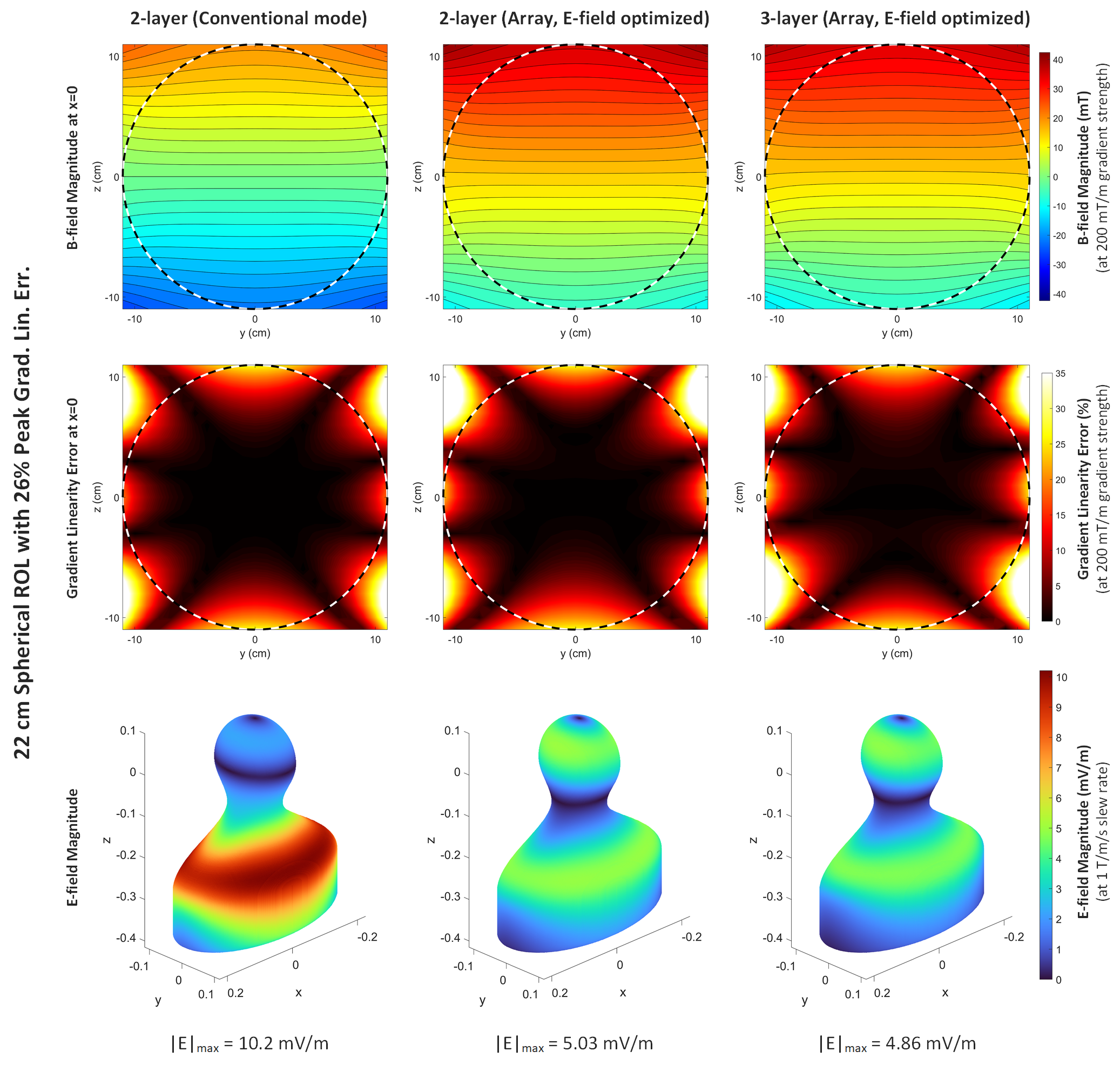
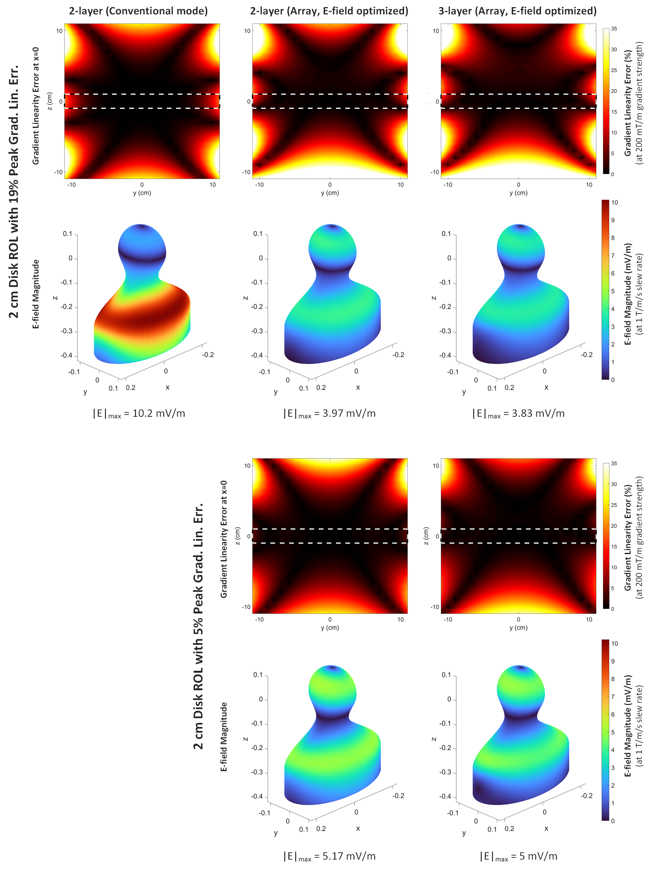
Fig.2 illustrates the magnetic fields, gradient field errors, and the magnitude of the E-fields on the surface of the body model for three different designs when the target field is generated within a 22-cm-diameter spherical ROL. The optimization procedure in the array coil design minimizes the induced E-fields by manipulating the B-field profiles (adding uniform magnetic fields) while preserving the target gradient. When comparing the 2-layer and 3-layer array modes to the 2-layer conventional mode, there are reductions in |E|max by 50.7% and 52.3%, respectively.Fig.3 demonstrates the same comparison when the target gradient field is generated within a circular disk in a transverse plane at $$$z=0$$$. By adjusting the peak gradient linearity error to 19% (linearity error of 2-layer conventional mode) the |E|max is reduced by 61% and 62.5% for the 2-layer and 3-layer array modes, respectively. In this scenario, the array configurations can also achieve lower linearity errors (for example, 5%) while minimizing the E-fields (49% and 51% reduction for 2-layer and 3-layer array mode, respectively).
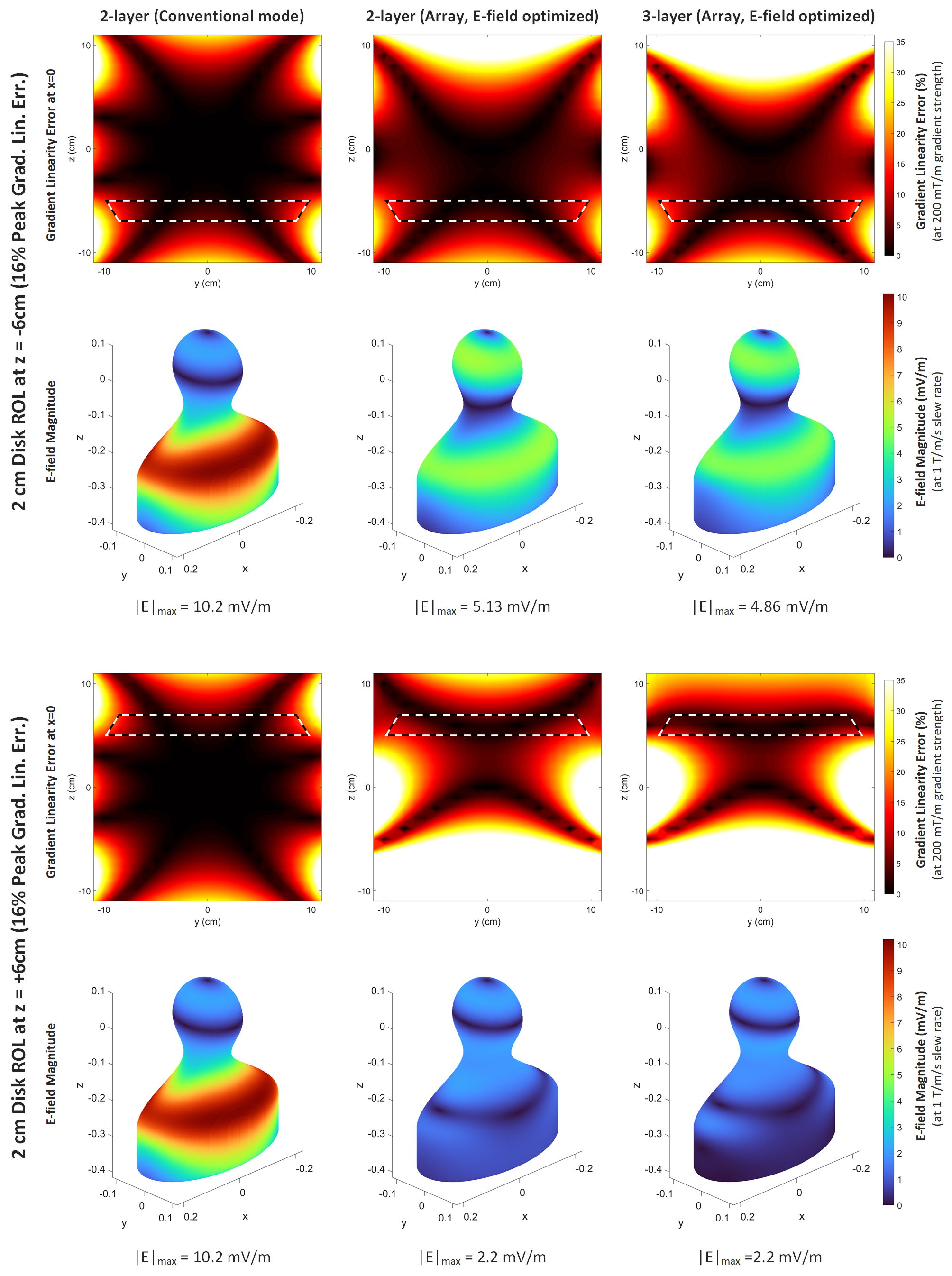
Fig.4 depicts the same comparison for the shifted disk ROLs (at $$$z=-6cm$$$ and $$$z=+6cm$$$). The array designs (2- and 3-layer) display significant reduction of E-fields, especially for the disk at $$$z=+6cm$$$ up to 78%.
Conclusion and Discussion
This study demonstrated effectiveness of a head-only Z-gradient array in reducing induced E-fields on the body model. An advantage of array design lies in its capacity to customize the ROL shape and level of linearity. Here, we have demonstrated that when a target gradient is required within a disk, the array design can attain perfect linearity (5% peak linearity error), while concurrently inducing E-fields of a magnitude comparable to those produced by a 22cm spherical ROL with peak linearity error of 26%. Our findings indicate that when utilizing the array configuration, the additional third layer does not result in a substantial change in E-fields. Nevertheless, it offers increased flexibility for improving other engineering metrics, such as coil efficiency, field linearity, and active shielding.Acknowledgements
We acknowledge “Sim4Life", where we conducted electromagnetic simulations, for providing an Academic License. "www.zurichmeditech.com”References
1. Davids M, Dietz P, Ruyters G, et al. Peripheral nerve stimulation informed design of a high-performance asymmetric head gradient coil. Magn Reson Med. 2023;90:784-801.
2. Foo TK, Laskaris E, Vermilyea M, et al. Lightweight, compact, and high‐performance 3 T MR system for imaging the brain and extremities. Magn Reson Med. 2018;80:2232-2245.
3. Foo TK, Tan ET, Vermilyea ME, et al. Highly efficient head‐only magnetic field insert gradient coil for achieving simultaneous high gradient amplitude and slew rate at 3.0 T (MAGNUS) for brain microstructure imaging. Magn Reson Med. 2020;83:2356-2369.
4. Babaloo R, Takrimi M, Atalar E, editors. Increasing Peripheral Nerve Stimulation Thresholds Using Gradient Array Coils. In Proceedings of Joint Annual Meeting of ISMRM-ESMRMB; London, UK, 2022. Abstract 580.
5. Babaloo R, Takrimi M, Atalar E, editors. Minimum Electric Field Gradient Array Body Coil with Adjustable Regions of Linearity. In Proceedings of the Annual Meeting of ISMRM; Toronto, Canada, 2023. Abstract 599.
6.Roemer PB, Wade T, Alejski A, McKenzie CA, Rutt BK. Electric field calculation and peripheral nerve stimulation prediction for head and body gradient coils. Magn Reson Med. 2021;86:2301-2315.
Figures