3930
Feasibility of motional eddy current-reduced, passive eddy current shielding of MRI gradient coils1GE HealthCare Technology and Innovation Center, Niskayuna, NY, United States
Synopsis
Keywords: Gradients, High-Field MRI
Motivation: High-performance gradient coils can induce substantial eddy current in the magnet causing heating and artifacts. Motional eddy current at high B0 exacerbates the problem.
Goal(s): To investigate the feasibility of patterned, additional passive shielding to reduce both electromagnetically-indued and motional eddy currents.
Approach: A proof-of-concept experiment was conducted in flat geometry, where shielding efficiency at 3T was compared between a solid copper and a patterned copper plate that mimicked the eddy current image of a driving coil.
Results: The leakage field of patterned copper agreed with theory and was more localized in frequency and space. The shielding efficiency was improved at high frequencies.
Impact: We demonstrated that vibration-induced motional eddy current of a passive conductive shield can be dramatically altered by eddy current cut-outs. The results can be used to build a compact, high-field scanners with reduced magnet-gradient interaction.
Introduction
The shielding efficiency of an actively shielded gradient coil1,2 is limited by current discretization as well as design tradeoffs. An additional passive shield by a continuous conductive layer can improve shielding3,4, as long as Lorentz-force vibration and motional eddy current are well contained5,6. Previous attempts to control the motional eddy current focused on structural measures4,7. Here we present a novel method to reduce the motional eddy current by cutting a pattern on the conductive shield according to the eddy current image of the leakage field8. The idea is demonstrated in a flat-geometry testbed experiment at 3T.Methods
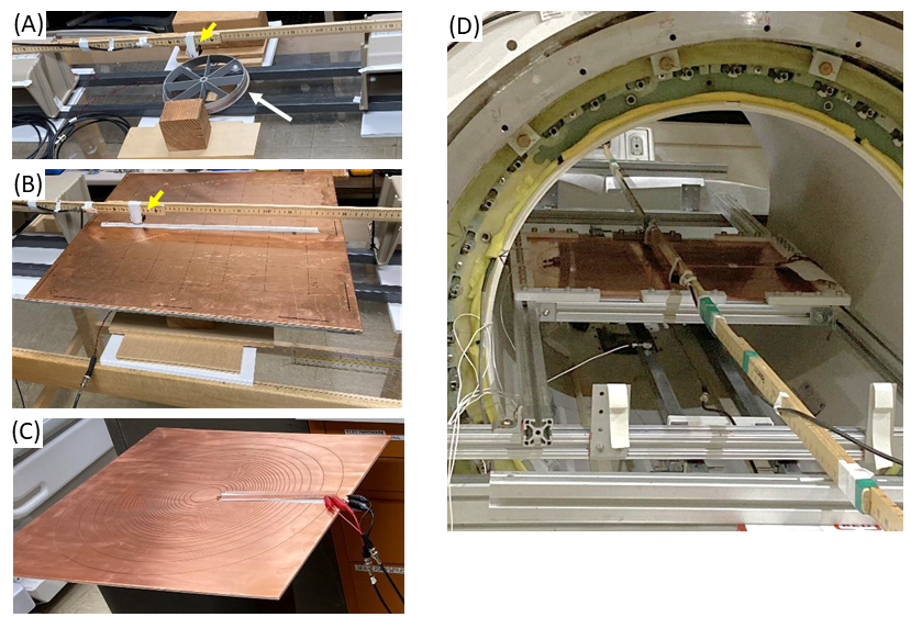
Frequency response function Figure 1 shows the experimental setup. Gradient leakage field was modeled by the magnetic field generated by a 20 cm-diameter, 10-turn circular loop coil (“driving coil”). The field was sensed by a 5 cm-diameter solenoidal pickup coil which was mounted on a wooden stick that could be translated horizontally (= z direction) above the driving coil. The experiment consisted of measuring the frequency response function (FRF), defined as the complex ratio between the pickup coil voltage and the driving coil current in the frequency domain, in the following four configurations. (1) First, the FRF was measured at 19 z locations (z = -9∆z to +9∆z, with ∆z = 2.54 cm) with no barrier between the two coils. (2) Second, a 1.6 mm-thick solid copper plate backed by 9.6 mm-thick fiberglass, both measuring 55.9 x 55.9 cm2 in plane, was inserted between the coils (Fig. 1B). (3) Third, the setup (with copper) was moved inside the bore of a 3T whole-body MRI magnet. (4) Finally, the solid copper plate was replaced by a copper plate with a spiral pattern (Fig. 1C) machined according to the simulated eddy current image of the driving coil (Fig. 1D). The spiral pattern was bridged by a copper strip to make a single closed loop that allowed current to flow in a predefined way.Impedance The complex impedance spectrum (5 < f < 50,000 Hz) of the spiral pattern was measured in the magnet, with the copper strip electrically open. This data was used to calculate theoretical leakage field of the patterned copper including any Lorentz-force effects.
Results
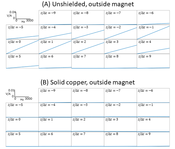
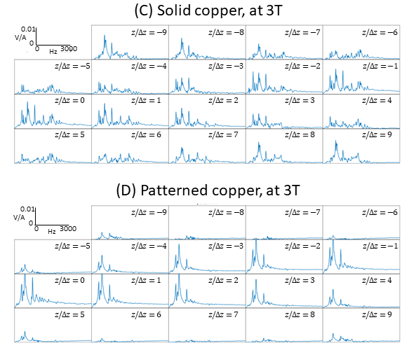
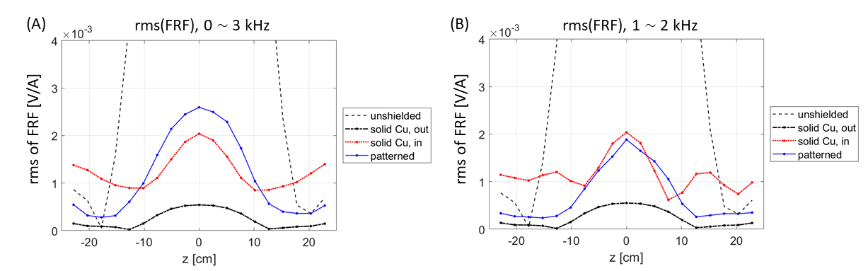
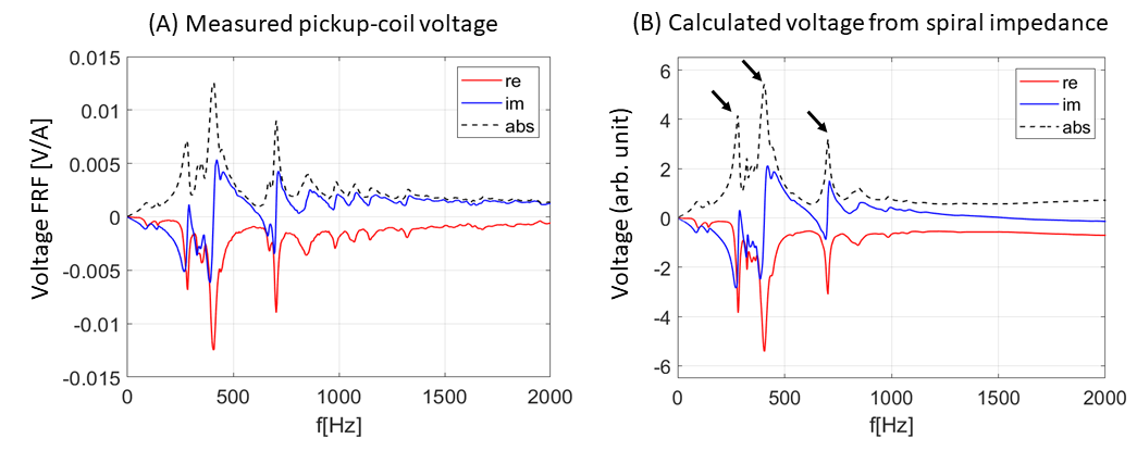
Figure 2 shows FRF at frequencies up to 3 kHz in the two configurations outside the magnet. Near complete shielding of the driving field by solid copper is evident. Figure 3(A) shows dramatic degradation of shielding performance of the copper plate at 3T, caused by Lorentz-force vibration and motional eddy current6. This effect has been associated with gradient-induced magnet heating in high-field MRI5. Figure 3(B) contains the main result of this study. It shows that eddy current pre-patterning of the passive shield substantially reduces leakage field in peripheral regions (|z/∆z| > 4) and at high frequencies (f >1 kHz). Although the leakage field was higher near z = 0 and f < 1 kHz, inspection of Fig. 3 reveals that the patterned-copper FRF is more localized in space and frequency, showing consistent spectral shapes across z. This reflects the leakage field originating from a single current mode defined by the pattern. The localization can also be appreciated in Fig. 4, where the root-mean-square of FRF as a function of z is plotted for different frequency bands. The patterned copper shield reduces FRF “energy” in the 1 ~ 2 kHz band at most z positions compared to solid copper.The spectral shape of the patterned-shield leakage field could be well predicted from impedance measurement as shown in Fig. 5. The main magneto-mechanical resonance peaks observed in Fig. 3(B) are reproduced in the calculated spectrum (Fig. 5(B)).
Discussion and Conclusion
The main idea of patterned passive shield is to preserve the desired, shielding eddy current while minimizing vibration-induced eddy currents inside the magnet. This strategy is most effective when the two eddy currents are orthogonal. Our results show that patterned passive shield fundamentally changes the spatial/spectral footprint of the motional eddy current, and can significantly reduce the leakage field in certain frequency bands and spatial regions. Leakage field peaks may further be reduced through structural reinforcements that target specific vibration modes. It should be noted that such measures as well as the exact cut-out patterns depend on the particular leakage field of a given gradient coil.In conclusion, we have demonstrated the concept of motional eddy current-reduced passive shield of an MRI gradient coil through mode-limiting cut-outs on a conductive plate. Improved leakage field suppression can reduce magnet-gradient interaction in high-field, high-gradient MRI scanners9,10.
Acknowledgements
This project was partly supported by NIH U01EB027696. The abstract does not necessarily represent the views of the funding agency.References
[1] P. Roemer et al., US 4,737,716 (1988), “Self-shielded gradient coils for nuclear magnetic resonance imaging”
[2] S-K. Lee and J. Schenck, Journal of Applied Physics 133, 174504 (2023), “Generalized magnetostatic target field method for shielded magnetic field coils in a separable coordinate system”
[3] G. Mulder et al., WO 00/25146 (2000), “MRI apparatus with a mechanically integrated eddy current shield in the gradient system”
[4] J-B. Mathieu et al., US 10,281,538 B2 (2019), “Warm bore cylinder assembly”
[5] Y. Hua et al., ISMRM 2012, Abstract 2580, “Gradient coil induced Joule heating in a MRI magnet”
[6] L. Jiang and T. Havens, IEEE Transactions on Applied Superconductivity 22(3), 4400704 (2012), “Environmental vibration induced magnetic field disturbance in MRI magnet”
[7] M. Westphal, US 7,514,928 B2 (2009), “Superconducting magnet configuration with reduced heat input in the low temperature regions”
[8] S-K. Lee and Y. Hua, US 11,774,531 B1 (2023), “Systems, assemblies, and methods of suppressing magnet-gradient interaction in magnetic resonance systems”
[9] T. K.-F. Foo et al., ISMRM 2023, Abstract 4586, “Compact 7T: Progress in construction and assembly of a low-cryogen, high-performance, head-only high-field MRI system”
[10] N. Boulant et al., Magnetic Resonance Materials in Physics, Biology, and Medicine 36, 175 (2023), “Commissioning of the Iseult CEA 11.7T whole-body MRI: current status, gradient-magnet interaction tests and first imaging experience”
Figures