3929
An Additional Gradient Axis Integrated into a Whole-Body Bore Coil for Prospective Silent MRI with Ultrasonic-encoding1Radiology, University Medical Center Utrecht, Utrecht, Netherlands, 2Spinoza Center for Neuroimaging, Amsterdam, Netherlands
Synopsis
Keywords: Gradients, Gradients
Motivation: To enable silent whole-body MRI using ultrasonic encoding, an additional low inductance gradient coil can be integrated between the RF-rods and RF-shield of a bore coil. However, the resulting effect on RF efficiency is unclear.
Goal(s): To demonstrate the feasibility of placing a gradient coil under the RF-shield without affecting RF efficiency.
Approach: A Maxwell gradient coil was integrated into a bore coil. We measured the gradient field and compared RF efficiency with and without the extra gradient.
Results: A gradient field was successfully induced without greatly affecting RF efficiency. For efficiency validations, volunteer images were obtained with and without the integrated coil.
Impact: Placing a low inductance gradient coil within the empty space in a bore coil allows an independent gradient axis to be driven at 20kHz. This may address high-voltage and PNS concerns when extending to whole-body silent MRI.
Introduction/Background
Previous work has shown that acoustic noise perception in MRI can be mitigated by very high slew rates, resulting in ultrasonic gradient coil vibrations at 20kHz1-3. This results in inaudible spatial encoding for most human subjects. Initial work on silent encoding focussed on a head gradient insert design. We aim to extend this concept to a whole-body silent gradient design. At ultrasonic frequencies, conventional whole-body gradients require high operating voltages due to the high coil inductance.Additionally, peripheral nerve stimulation is expected due to their large linear gradient field4. These limitations could be mitigated using a separate nonlinear gradient axis with a reduced diameter closer to the patient. This lowers the required voltages and reduces peak fields and the chance of PNS5. We propose an additional ultrasonic-only gradient axis in the space between the radiofrequency (RF) rods and RF-shield. The use of this space avoids further modifications to the MRI setup to accommodate an additional gradient axis and maintains the available bore space for the patient. However, the proximity to RF-hardware may affect RF efficiency, and any induced eddy currents could heat the RF-shield. This work demonstrates the feasibility of integrating a gradient coil into a whole-body bore coil with minimal effect on the RF-transmit efficiency. We also quantify the coupling to the RF-shield.
Methods
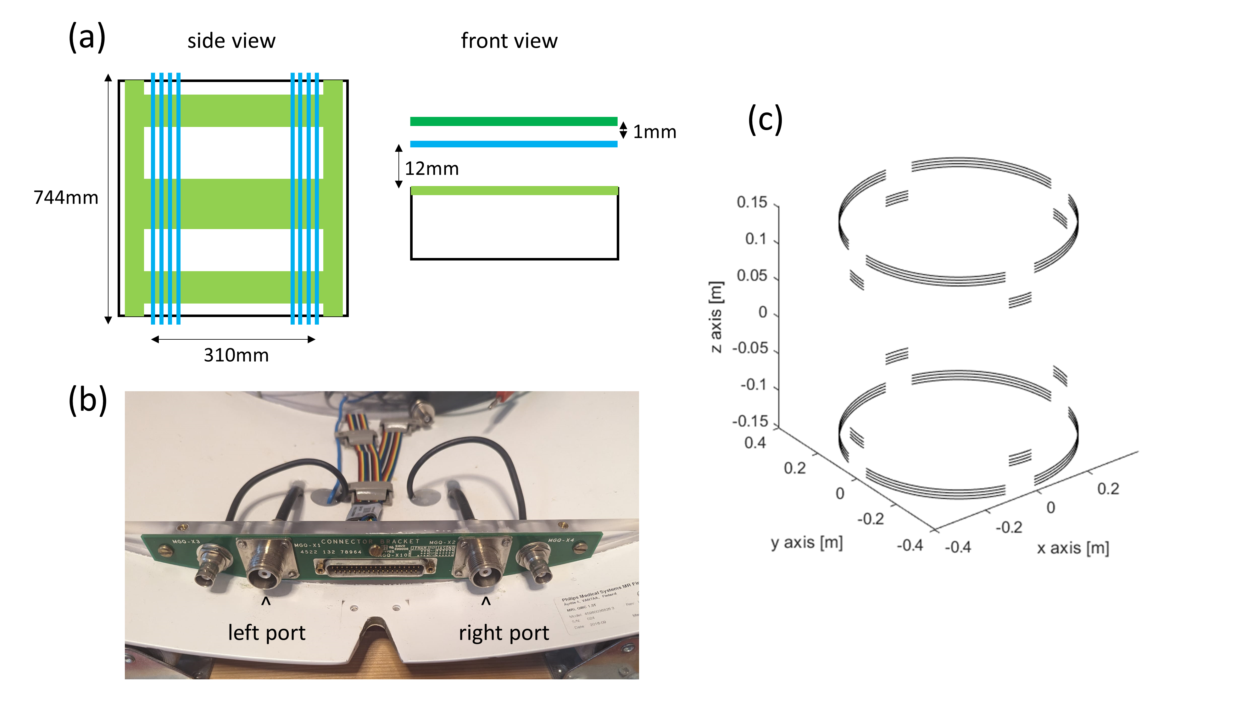
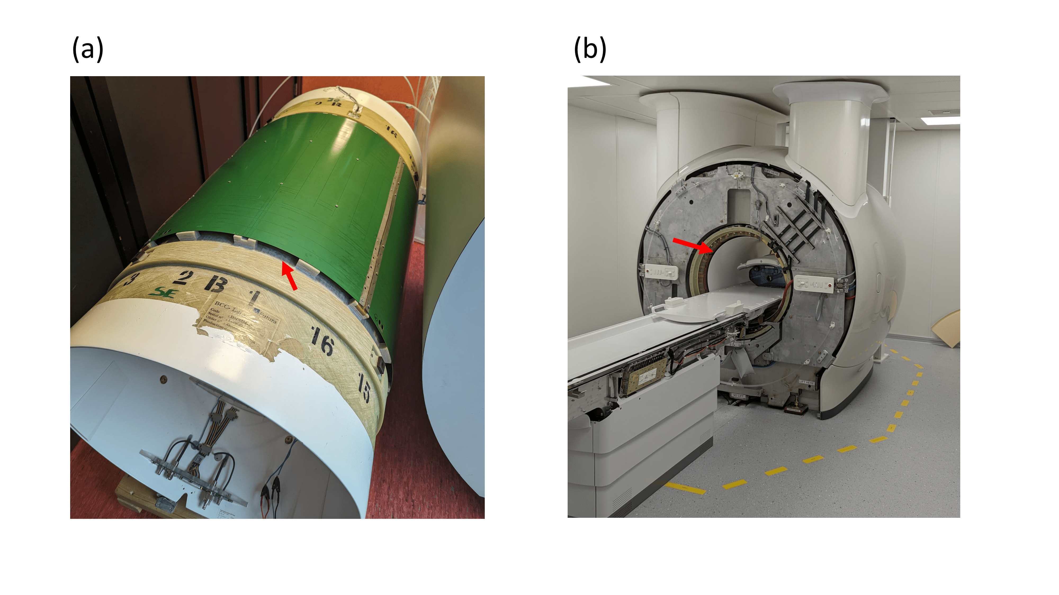
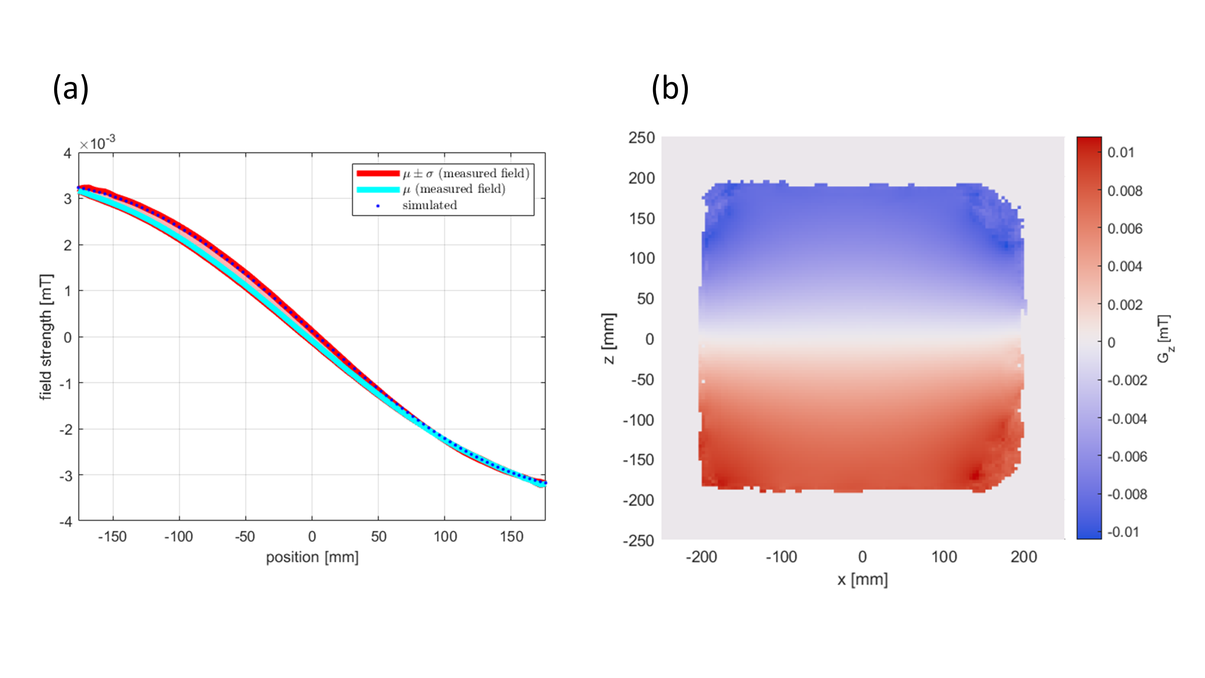
A 1.5T MRI scanner (Philips) bore coil was modified by placing a Maxwell gradient coil in the space between the RF rods of the bore coil and the RF-shield (Figure 1). The gradient coil was made of 4 copper windings of radius 37.2cm on opposite ends separated by 31cm. On one end, windings were wound clockwise and anticlockwise on the opposing end, generating a gradient field along the z-direction. We performed impedance measurements at 20kHz (for prospective ultrasonic-encoding) to estimate the power deposited by the gradient in the RF-shield.RF efficiency values were recorded before and after integrating the gradient coil into the bore coil at 64MHz for 1.5T. The B0 field was first mapped in a phantom with no current flowing in the gradient coil, then B0 mapping was done using a current of 1-3A for both polarities (Figure 2). From this, the gradient field was determined for each current value and polarity and the average field was determined and normalised to a current of 1A to obtain the gradient coil efficiency. Next, a volunteer's abdomen was scanned and the RF-power was recorded to quantify the loss in RF-transmit efficiency. We then removed the integrated gradient bore coil and installed an unmodified bore coil. Measurements were retaken to gauge the difference in image quality and RF-power depending on the presence of the gradient coil. Both measurements were completed using the same RF-receive coil.
Results
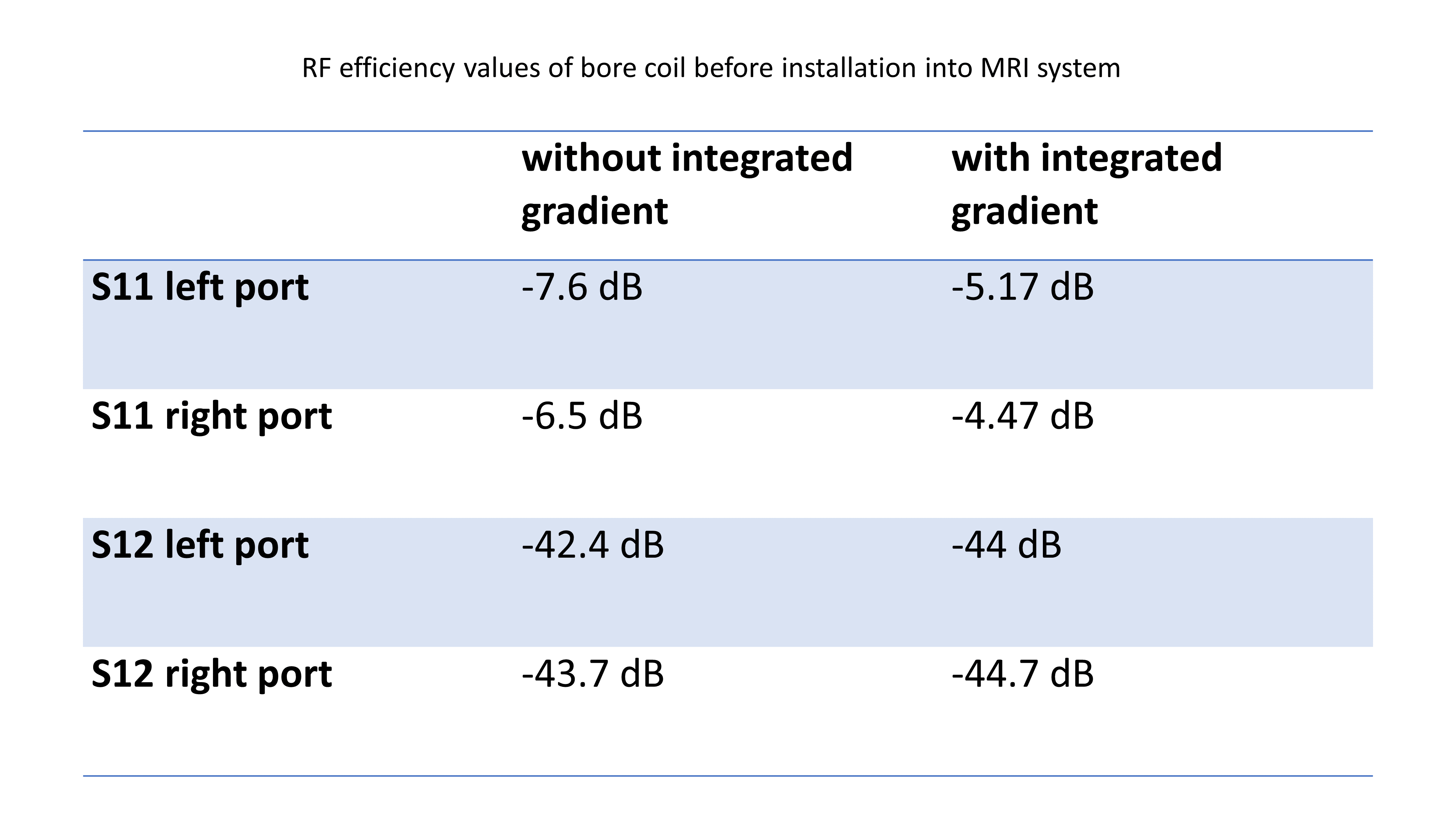
Without the RF-shield, the gradient coil had a measured inductance and resistance of 65.3µH and 288mΩ, respectively, at 20kHz. With the shield, these values were 54.2µH and 1170mΩ, respectively. Therefore, this rudimentary design dissipates a factor of ~5 in power into the shield due to resistive losses. RF efficiency measurements were unaffected or even slightly improved with the integrated gradient coil present (Table 1).Figure 3a shows a 1D profile through the centre of the induced gradient field. A 1D profile of a simulated gradient field is also shown for comparison. A 2D profile of the induced gradient field is shown in Figure 3b. The gradient field efficiency was determined to be 0.028mT/m/A. When tuning this coil to 20kHz and matching to 1Ω, using a standard 1kA gradient amplifier (Prodrive), the gradient field amplitude would be 28mT/m with a slew rate of 3519T/m/s. This projected slew rate value is more than an order of magnitude higher than conventional gradient systems.
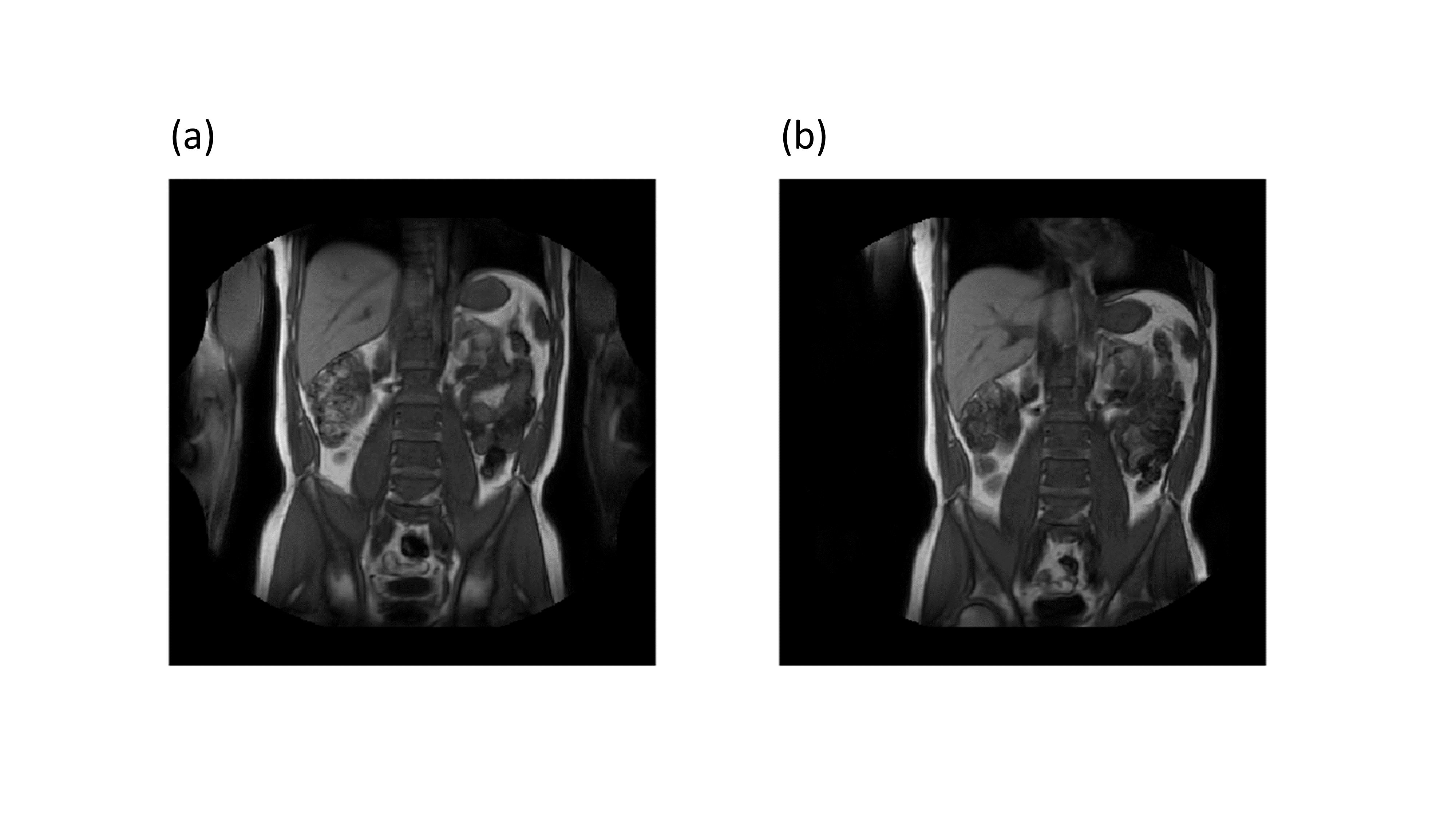
Scans of the volunteer's abdomen are shown in Figure 4. The likeness of the images indicates that similar RF-transmit efficiency was achieved. This was also predicted quantitatively, as integrating the gradient coil required only a 4.5% increase in power to achieve the same RF-transmit efficiency as the unmodified body coil.
Conclusion
We demonstrated the feasibility of integrating a gradient coil into the empty space between the RF rods and RF-shield of a whole-body bore coil. The integrated gradient had minimal effect on the RF efficiency, requiring only a 4.5% increase in power. Yet, a factor ~5 power deposited in the shield is significant. This could be mitigated by developing an actively shielded version of the integrated gradient coil or extra cooling of the RF-shield. With this, we believe the integrated coil could be driven at 20kHz to achieve an ultrasonic integrated whole-body gradient.Acknowledgements
This work has been financed by NWO grant number 18951.References
1. Versteeg E, Klomp DWJ, Siero JCW. A silent gradient axis for soundless spatial encoding to enable fast and quiet brain imaging. Magn Reson Med. 2022;87(2):1062-10732. Versteeg E, van der Velden TA, van Leeuwen CC, Borgo M, Huijing ER, Hendriks AD, Hendrikse J, Klomp DWJ, Siero JCW. A plug-and-play, lightweight, single-axis gradient insert design for increasing spatiotemporal resolution in echo planar imaging-based brain imaging. NMR Biomed. 2021;34(6):e4499
3. Versteeg E, Klomp DWJ, Siero JCW. Accelerating Brain Imaging Using aSilent Spatial Encoding Axis. Magn Reson Med. 2022;88:1785-1793
4. Ham CL, Engels JM, van de Wiel GT, Machielsen A. Peripheral nerve stimulation during MRI: effects of high gradient amplitudes and switching rates. J Magn Reson Imaging. 1997 Sep-Oct;7(5):933-937
5. Hidalgo-Tabon SS. Theory of gradient coil design methods for magnetic resonance imaging. Concepts Mag Res Part A 2001;36A:223-242.
Figures