3915
Eddy current heating of weakly conductive objects in high-performance gradient coils1GE HealthCare Technology and Innovation Center, Niskayuna, NY, United States, 2GE HealthCare, Waukesha, WI, United States
Synopsis
Keywords: Safety, Gradients
Motivation: Conductive objects such as RF shield can pose heating risk due to eddy current in fast-switching gradient fields.
Goal(s): To develop a systematic method to calculate eddy current heating when multiple gradient coils pulse simultaneously with independent waveforms. We explicitly consider interaction of different coils.
Approach: Our method was tested against experimental measurement of temperature rise in a high-performance head-only gradient coil (MAGNUS) at 3T.
Results: Predicted and measured local eddy current heating showed good qualitative agreement. Importance of coil coupling was demonstrated by the experimental data.
Impact: We present a systematic method to calculate eddy-current heating induced by multiple independent field coils. The work permits accurate prediction of RF shield heating in high-performance gradient systems to ensure patient safety.
Introduction
Gradient-induced eddy current heating of conductive objects such as RF shield1-3, passive shims4, implants5, and interventional devices6 can pose patient safety risk and degrade system performance. Most theoretical work on this subject has considered a single coil3 or a small object where the applied field was assumed uniform5. Uniform applied field is not adequate for large objects such as an RF shield or for compact gradient coils. We present a theory to calculate multi-coil eddy current heating of weakly conductive but spatially extended objects, and illustrate its application through simulation and experiments.Theory
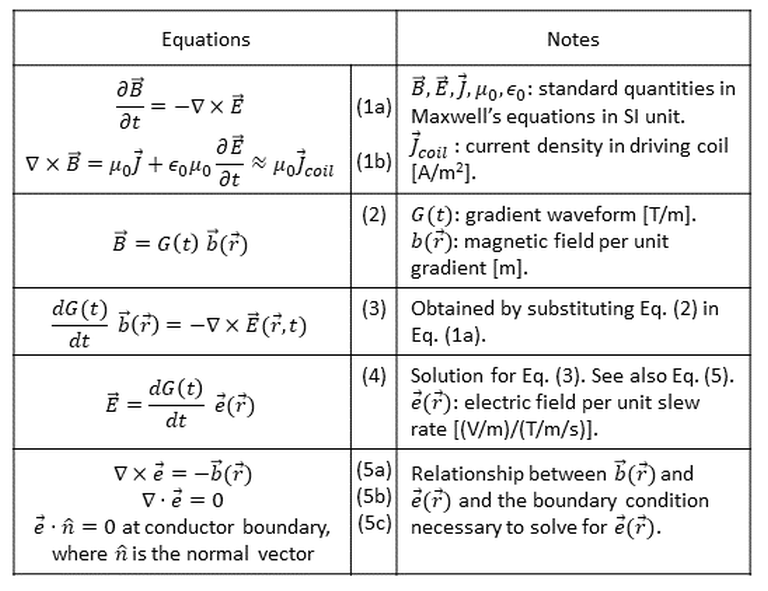
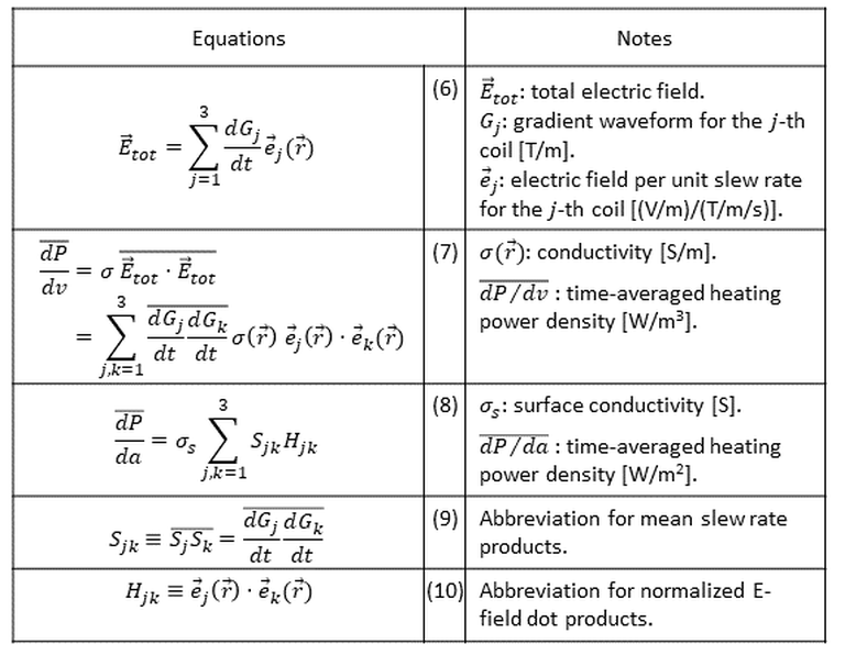
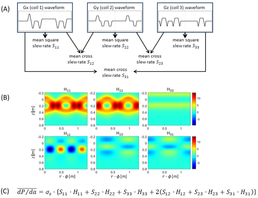
At typical gradient frequencies, eddy currents in many MR-compatible metals are magnetically weak but can cause significant Joule heating. In this low-frequency regime, the Maxwell’s equations permit time-space separation of both the magnetic and electric (E) fields (Fig. 1). For a single gradient coil, the E field in the object can be expressed as a product of the instantaneous slew rate dG/dt and a static, normalized electric field vector (Eq. (4)). The latter depends on the coil design and the object geometry, but is independent of the waveform (Eq. (5)). The E fields and eddy currents generated by different coils are additive (Eq. (6)). The Joule heating power, however, is quadratic to the eddy current and involves coupling between the coils (Eq. (7)). If the conductive object is a thin plate with surface conductivity σs , the time-averaged power density can be expressed in terms of the mean-square and mean-cross slew rates Sjk and the normalized E-field dot products Hjk (Eqs.(8-10)). Both Sjk and Hjk are symmetric with six unique elements for a 3-axis gradient set. Figure 3 illustrates calculation of Sjk and Hjk for a head-only gradient coil MAGNUS 3.0T (GE HealthCare, Waukesha, WI, USA).Methods
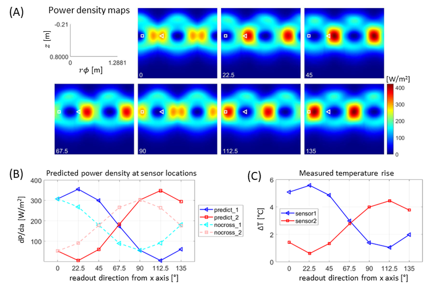
All experiments were conducted in the MAGNUS system equipped with a standard 2MVA driver delivering 300 mT/m, 750 T/m/s performance. Two thermistors were attached on the RF shield near two hot spots determined from thermal camera measurements3,7. A coronal-plane EPI sequence with readout in the right/left (RL) direction was run for 10 minutes and the temperature rise for both sensors was recorded. This was repeated while the scan plane was rotated such that the readout direction rotated in the laboratory XY (=axial) plane, every 22.5° from 0 to 135°. The RMS slew rate of the readout gradient was 241 T/m/s. The coupling S12 (between X, Y gradients) was the largest at 45° (1702 (T/m/s)2). For simulation, the Hjk maps were calculated on the RF shield from numerical solution of Eq (5) adapted for a cylindrical surface3 in Matlab. As-designed magnetic field maps for unit gradient strengths were used as an input. Eleven brain imaging pulse sequences were analyzed for the slew-rate parameters Sjk, from which the power density was computed using Eq. (8).Results
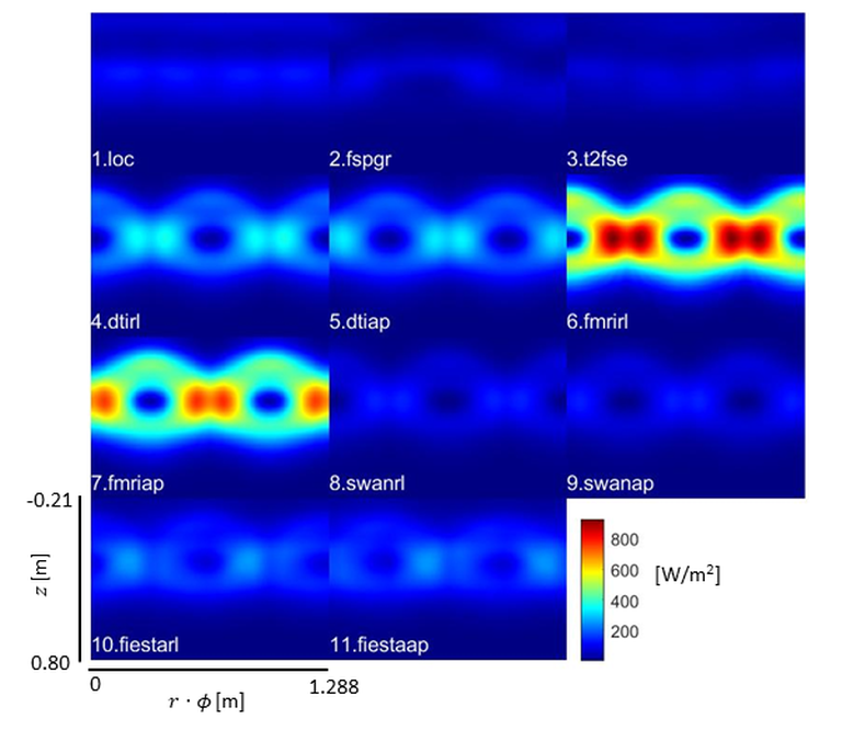
Figure 4 shows simulated power maps for all tested sequences. Apart from the overall scale and 90° shift between different readout directions, significant qualitative differences were observed between fMRI and FIESTA. This is caused by greater waveform overlap between readout and slice-selection in FIESTA compared to EPI. Figure 5 compares predicted and measured heating at two spots on the RF shield as the EPI readout direction rotated. Surprisingly, the heating maps of Fig. 5(A) did not simply shift to the right with the rotation. This is a consequence of the fact that, at the RF shield, the transverse gradient fields no longer have the cos(φ) or sin(φ) dependence. The predicted local power density at the sensor locations as a function of the readout direction (Fig. 5B) shows good qualitative agreement with experimental temperature data (Fig. 5C). The dashed lines of Fig. 5B indicate the power densities if the interaction terms (with different j, k) are ignored in Eq. (8). The lines clearly miss the data in Fig. 5C.Discussion & Conclusion
We presented theoretical analysis of eddy current heating induced by multiple, independently driven magnetic field coils and tested its validity through RF shield temperature measurement. The theoretical formalism involving quadratic forms is similar to SAR calculation in parallel transmit, where the time-space separation results from single-frequency harmonic analysis. Our analysis did not include cooling and thermal transport, which can affect the measured temperatures. This can partly account for the deviation of Fig. 5C from Fig. 5B (solid lines); sensor 2 may have been better cooled. The presented method can provide a systematic way to predict eddy current heating in high slew-rate gradient systems and help devise preventive measures through sequence modification. The method is also directly applicable to matrix gradient coils.Acknowledgements
This work was partly supported by CDMRP W81XWH-16-2-0054. This presentation does not necessarily represent the views of the funding agency.References
[1] R.W. Brown, US 9013185 B2 (2015), “Optimized RF shield design”
[2] B. Lee et al., MRM 79, 1745-1752 (2018), “Low eddy current RF shield enclosure designs for 3T MR applications”
[3] S-K. Lee et al., 31st Annual Meeting of ISMRM, Toronto, Canada, Abstract 4566 (2023), “Analytical expression for gradient eddy current-induced power dissipation in a thin conductive shell: A model for RF shield heating”
[4] El-Sharkawy et al., MAGMA 19(5), 223-236 (2006), “Monitoring and correcting spatio-temporal variations of the MR scanner’s static magnetic field”
[5] A. Arduino et al., MRM 88, 930-944 (2022), “A contribution to MRI safety testing related to gradient-induced heating of medical devices”
[6] S. Lechner-Greit et al., Journal of Therapeutic Ultrasound 4, 4 (2016), “Minimizing eddy currents induced in the ground plane of a large phased-array ultrasound applicator for echo-planar imaging-based MR thermometry”
[7] D. Kang et al., 31st Annual Meeting of ISMRM, Toronto, Canada, Abstract 4426 (2023), “Experimental and theoretical investigation of eddy current heating of RF shield in a high-performance gradient system”
Figures