3750
Combining the advantages of FDTD and FEM for MRI RF safety evaluation using the Huygens method1Cambridge Consultants, Singapore, Singapore, 2Cambridge Consultants, Cambridge, United Kingdom, 3Cambridge Consultants, Boston, MA, United States, 4Biomed-EM Group, Singapore University of Technology and Design (SUTD), Singapore, Singapore, 5Department of Radiology, Martinos Center for Biomedical Imaging, Boston, MA, United States
Synopsis
Keywords: Safety, Safety, Modelling, MRI
Motivation: MRI RF safety evaluation requires simulations of many coils and body models, which is typically done using FDTD or FEM. These have complementary weaknesses, therefore we propose to combine them.
Goal(s): We propose a simulation process that combines FEM with FDTD via the Huygens’ principle.
Approach: We first compute the incident electric field created by the coil alone using FEM. Second, we compute field perturbations created by the body model using an FDTD Huygens’ implementation.
Results: The proposed method agrees well with the all-FDTD calculation at 64 MHz, but allows more efficient and flexible modelling of RF coils.
Impact: We propose a robust and flexible simulation method combining the strengths of FEM and FDTD via the Huygens principle that expedites coil and implant (ISO/TS10974 Tier 3) RF safety evaluations.
Introduction
Active implantable medical devices (AIMD) are more and more common, which raises MRI safety and compatibility concerns. RF interactions between MRI and implants are typically characterized using one of the four-tier approach in TS/ISO 10974 1, with Tier 3 being the most used as it leads to a relatively robust and fast evaluation. A central component of Tier 3 is the tangential electric field (E-field) distribution created by the MRI coil in realistic body models along the implant path. For this analysis to be robust, many simulations must be performed for various coils, body models and landmark positions.Detailed human body models, such as the IT’IS/FDA Virtual Population 2, are naturally compatible with FDTD (Finite Difference Time Domain) solvers because the voxel discretization of the Yee cell matches the voxels imaged with CT and MRI 3. However, FDTD Yee voxels yield poor staircase geometrical representation of MRI coils composed of thin copper sheets. In addition, MRI coils have tuning and matching capacitors that are also difficult to represent with voxels. Instead of simulating capacitors within the field solver domain, it is easier to decouple the field simulation step from tuning/matching step in a process called co-simulation. Finite Element Modelling (FEM) is the ideal tool for this task as it allows calculation of the entire scattering matrix of the coil in a single simulation, whereas FDTD requires N separate simulations, where N is the number of capacitors to be optimized. Additionally, FEM excels at discretization of thin surfaces since it combines tetrahedron (for volume discretization) and triangle elements (for surfaces).
We propose a method that combines the strength of FEM in coil modelling with that of FDTD in body model simulation using the Huygens’ method 4 and report the accuracy in 1.5 T simulations.
Methods
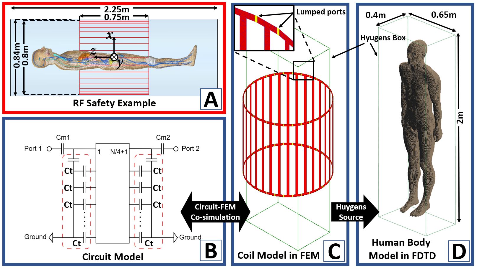
Figure 1A shows the coil modelled in this work (1.5-T 32-rung highpass birdcage), loaded with the Duke body model from the Virtual Family 2 centered with its pelvis at isocenter. The workflow is as follows (Steps 1-3: FEM co-simulation, Step 4: Huygens):Step 1: The unloaded birdcage coil (no body model) is simulated in FEM Ansys HFSS (Canonburg PA, USA). Tuning capacitors are replaced by ports.
Step 2: The resultant scattering matrix is loaded into the circuit simulator Nexxim. Tuning and matching capacitors are added in the circuit model and are optimized at this stage. Two quadrature ports are added, driven with a 90° phase difference.
Step 3: The circuit is solved and the port currents and voltages are applied to the sources of the FEM model in HFSS, thus generating the incident field 5,6.
Step 4: The inciden field is imported into FDTD as AC Huygens source, and the field perturbation by the body model (no coil model) is solved.
Results
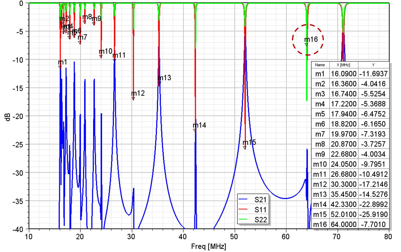
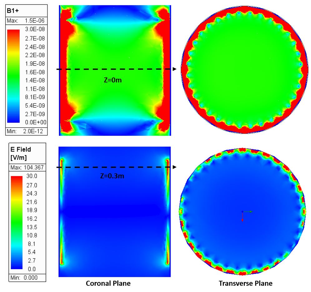
The initial value of the tuning capacitors calculated with Birdcage Builder 7 is 79.25pF, which was refined to 197.4pF after tuning using FEM and co-simulation (desired 16th mode of the coil 8, see Figure 2).The expected uniform B1+ distribution created by the coil is shown in Figure. 3, as is the electric field with the typical sinusoidal current distribution around the rungs visible in the transverse plane.
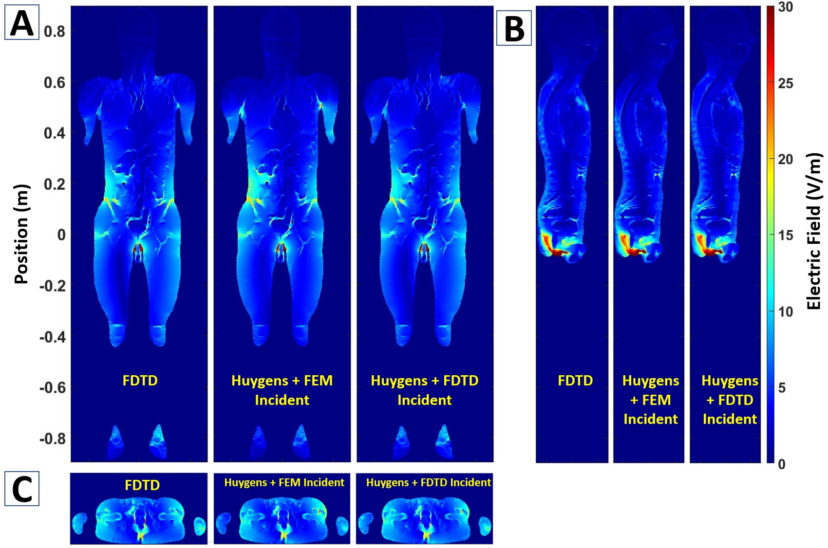
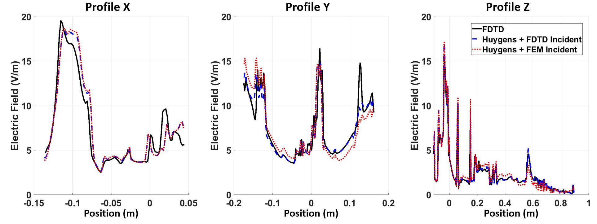
The scattered fields in the body are then computed using the FDTD method and the Huygens’ method with incident input fields from FEM. To validate our approach, the human body is simulated with an ideal birdcage coil in FDTD directly, whose rungs are replaced by ideal current sources. The incident field from this ideal coil is also employed to simulate the body using Huygens method. While the grid resolution of the body is 2mm, the grid resolution of the coil in FDTD is 20mm to reduce the total voxels. There is a good visible agreement between those E-field maps in Figure 4 and profiles in Figure 5.
Discussion and Conclusion
Our results show that the Huygens’ method reproduces accurately the electric field distribution in complex voxel body models (here, Duke). The method decouples the coil and the body model simulations, thus allowing to employ the best numerical tool for each task. The result is a robust, flexible, convenient method for RF safety evaluations in realistic body models. This approach is especially suited to the simulation of many body models in the same coils, which is needed for Tier 3 ISO/TS 10974, since the incident field is computed once and the Huygens’ FDTD solves can be run efficiently in batch mode.Acknowledgements
No acknowledgement found.References
- ISO/TS 10974 2018. Assessment of the safety of magnetic resonance imaging for patients with an active implantable medical device.
- The Virtual Population. High-resolution anatomical models for computational life sciences. SPEAG AG, Flyer, EuCAP 2016, Davos, Switzerland, Apr. 2016.
- https://en.wikipedia.org/wiki/Finite-difference_time-domain_method.
- Merewether DE, Fisher R, Smith FW. On Implementing a Numeric Huygen’s Source Scheme in a Finite Difference Program to Illuminate Scattering Bodies. IEEE Trans Nucl Sci. 1980;27(6):1829–33.
- Kozlov M, Turner R. Fast MRI coil analysis based on 3-D electromagnetic and RF circuit co-simulation. Journal of Magnetic Resonance. 2009;200(1):147–52.
- Guérin B, Gebhardt M, Serano P, Adalsteinsson E, Hamm M, Pfeuffer J, et al. Comparison of simulated parallel transmit body arrays at 3 T using excitation uniformity, global SAR, local SAR, and power efficiency metrics. Magn Reson Med. 2015 Mar;73(3):1137–50.
- Chih-Liang C, Collins CM, Li S, J. Dardzinski B, B. Smith M. BirdcageBuilder: Design of Specified-Geometry Birdcage Coils with Desired Current Pattern and Resonant Frequency. Concepts Magn Reson. 2002;15(2):156–63.
- Kim YC, Kim HD, Yun BJ, Ahmad SF. A Simple analytical solution for the designing of the birdcage RF coil used in NMR imaging applications. Applied Sciences. 2020;10(7).
Figures