3742
Study of RF-Induced Heating in Active Implantable Medical Devices with Open Impedance Leads at 1.5T MRI1ECE, University of Houston, Houston, TX, United States, 2Abbott, Plano, TX, United States
Synopsis
Keywords: Safety, Safety
Motivation: The RF-induced heating from different configurations of open impedance leads connected to a commercial Pulse Generator (IPG) was investigated. It was observed the RF-induced heating from open impedance leads can behave differently from an intact lead.
Goal(s): Heating in the distal end of open impedance leads need to be estimated.
Approach: Transfer functions and heating measurements were performed.
Results: Most open-impedance configurations led to increased electrode heating with the highest heating occurring when only a single channel of the eight-channel lead was left intact. Additionally, significant differences in heating were found depending on the location of the open impedance.
Impact: Patients with open impedance fractured leads could take MR scan with the help of this study.
Introduction
RF-induced heating poses safety risks when AIMD patients undergo MRI scans. The interaction between these metallic leads and the emitted RF signals from the scanner can create an "antenna effect" and results in the risk of thermal injury1. A typical AIMD will include multiple channels, though not all channels will be used for nerve stimulation therapy in most patients. Therefore, open channels may not necessarily be detrimental to the patient in terms of ability to receive therapy. Despite this, the open impedance channels are typically detected within the device, and MR scanning with open impedance leads is contra-indicated by most device manufacturers due to the possibility of the open impedance condition altering radiofrequency (RF) energy coupling on the leads and changing the RF-induced heating effect on electrodes.Methods
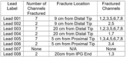
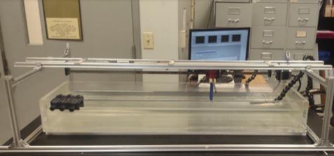
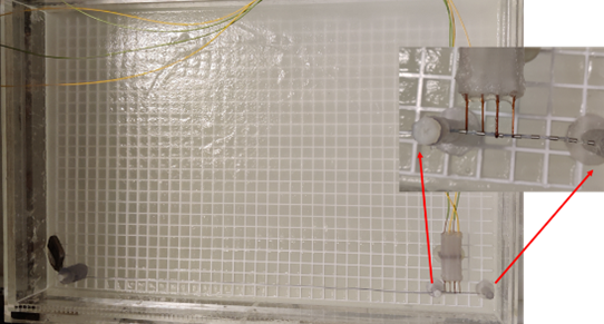
A commercially available spinal cord stimulator and eight, eight-channel 64 cm leads was used in this study. Eight configurations were examined, including an intact lead configuration, four configurations with two open impedance channels, and three configurations with seven open impedance channels (Figure 1). For open impedance configurations, the leads were modified by cutting the inner conductors of either two or seven of their channels at various points along the lead body. For each configuration, the transfer function (TF) and RF-induced heating were measured at 64 MHz. To measure the RF-induced heating, the device was placed inside the ASTM phantom (636 × 408 × 90 mm) filled with gel (σ = 0.47 S/m, εr = 81) and excited using a 1.5T birdcage coil (Figure 2). The AIMD system was placed 45 mm beneath the top surface of the 90 mm height gel. RF-induced heating was measured for 1 minute for each case with the leads routed along a straight pathway near the phantom edge as shown in Figure 3. Temperature rise was measured on each electrode using Neoptix Fiber optic probes. Electrodes were numbered P1-P8 from distal to proximal for analysis. Tangential E-field values based on simulation data was extracted for the lead pathway and were used to calculate expected temperature rise for TF scaling.Results
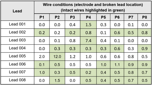
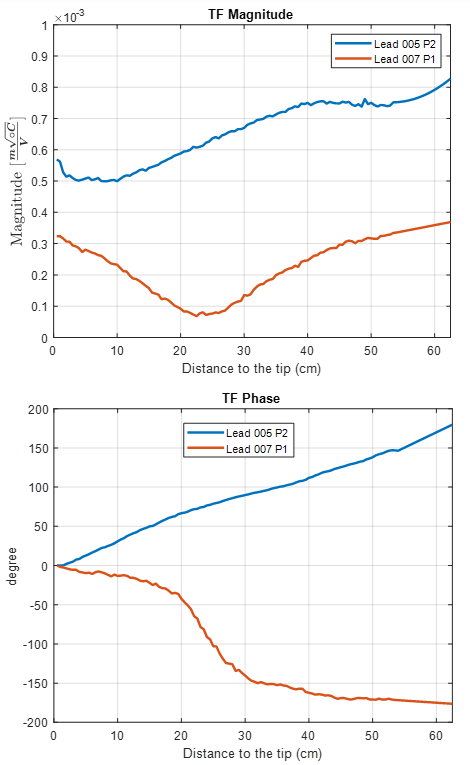
The heating results of both in-vitro heating measurement and sample of transfer function are given in Figure 4 and Figure 5.Discussion
The temperature rise on the electrodes of an open impedance lead is significantly different from that of an intact lead for configurations with higher numbers of open circuit channels. In particular, configurations 003 and 005 led to maximum temperature rises 7.0 and 12.4 times higher than seen in the intact lead configuration. In all configurations with seven open channels, the highest temperature rises were seen on the intact channel, presumably due to the RF energy redistribution from open wires into the intact wire where it is then dissipated through the electrode of the intact wire. These open impedance configurations generally led to higher TF magnitudes than for the intact lead, as shown in the example TF comparison in Figure 5. The TF phase also varies significantly from the intact lead to the open impedance lead. Notable differences were seen in heating between all seven-channel open configurations, suggesting that temperature rise is dependent not only on the number of open impedances but also their location along the lead.For leads with only two open impedance channels, temperature rises were more modest. The highest temperature rises in these configurations were comparable to those of the intact lead, suggesting that there may be potential for MR-conditionality of leads with limited numbers of open impedances in the future. Among these configurations, configurations 002 and 004 led to slightly decreased max temperature rises and configurations 006 and 008 led to slightly increased temperature rises, though all were within measurement uncertainty (σ=25%±1°C).
Conclusion
This study has demonstrated that open impedances lead can increase the RF-induced heating under MRI RF coil emission but that these changes may be only modest for configurations with limited numbers of open impedances. Based on these results, changes in RF-induced heating appear to show strong dependency on both the number of open impedance channels and the positioning of the open impedance points along the lead body. Evaluation of both factors would be crucial for MR safety testing of these leads.Acknowledgements
No acknowledgement found.References
J. Liu, J. Zheng, Q. Wang, W. Kainz and J. Chen, "A Transmission Line Model for the Evaluation of MRI RF-induced Fields on AIMDs," IEEE Transactions Microve Theory and Techniques, 2018.Figures