3734
Reducing acoustic noise in head-only scanners with padding on the RF coil1NeuroSpin, CEA, Gif sur Yvette, France, 2Advanced MRI technologies, Sebastopol, CA, United States, 3Helen Wills Neuroscience institute, University of California, Berkeley, CA, United States, 4Siemens Medical Solutions USA Inc, Berkeley, CA, United States, 5University of California, San Francisco, CA, United States, 6San Francisco VA Health Care System, San Francisco, CA, United States, 7Imaging Centre of Excellence, University of Glasgow, Glasgow, United Kingdom
Synopsis
Keywords: High-Field MRI, Safety
Motivation: Acoustic noise can be a severe physiological barrier for acquisitions at high field.
Goal(s): To isolate the main source of acoustic noise in the NexGen 7T scanner and investigate ways to reduce it.
Approach: Vibration and acoustic noise measurements were performed. Sponge window seal materials were stuck on the RF coil to attempt altering its vibrations and decrease acoustic noise.
Results: The experimental data is consistent with noise induced by eddy-currents on the RF shield. Altering its vibrations allowed decreasing sound level by up to 10 dB at some EPI echo-spacings.
Impact: Identifying the main source of acoustic noise shall open new research avenues to mitigate acoustic noise
Introduction
Higher magnetic field, gradient strength and slew rates increase vibrations and acoustic noise according to the Lorentz force. Large acoustic noise is always detrimental to volunteer’s comfort and may become in the future one of the most severe obstacles for MRI operation at higher fields. Acoustic noise in MRI is often attributed to the strong vibrations of the gradient coil and in this context, acoustic modes in the magnet bore can play a role1. Foam rings can then be placed around the boreliner to attenuate sound, beyond which very few means seem readily available to the MR users for additional soundproofing, besides usual hearing protection or sequences avoiding mechanical resonances. In this work, we investigated the origin of acoustic noise with vibration and sound pressure level (SPL) measurements on the NexGen 7T scanner, which is equipped with the investigational high performance, Impulse, head gradient coil2. We establish for this setup that most of the noise in fact originates from the eddy-currents induced in the RF shield of the RF coil. And we investigate possible ways to affect its vibrations and decrease SPLs.Methods
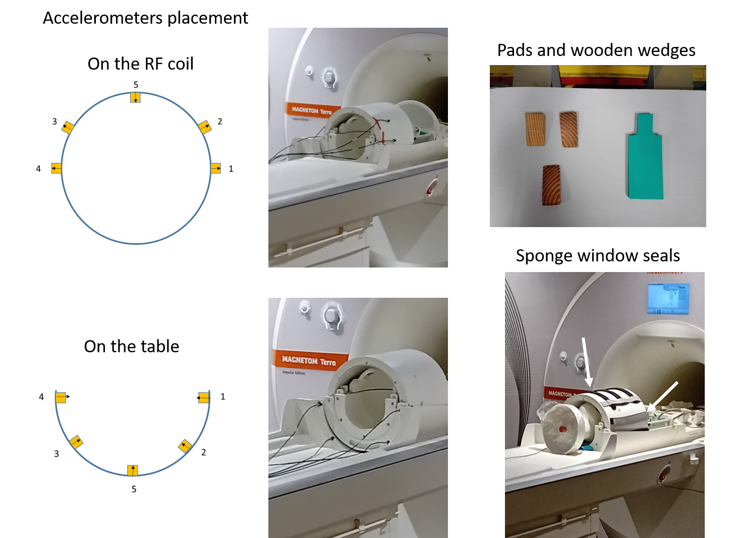
Measurements were performed on the 7T NexGen scanner equipped with the investigational Impulse head gradient (max gradient strength = 200 mT/m, max slew rate = 900 mT/m/ms) and a 8Tx-64Rx head coil2 (MRCoilTech, Glasgow, UK). SPL measurements (Optoacoustics, Mazor, Isreal) were first performed with continuous wave sinusoidal gradient waveforms at constant frequency and amplitude (5 mT/m), for each gradient axis, in 25 Hz steps, with and without the RF coil and at the right ear location of an anthropomorphic phantom. Vibration measurements were performed on the external surface of the RF coil and on the patient table using mono axial accelerometers (B&K, Naerum, Denmark) with gradient sweeps over the 0-3 kHz range in 2 min and at 5 mT/m amplitude. To ascertain the possible influence of mechanical coupling between the patient table and the RF coil, three different supporting materials between the two were tried: soft Sylodyn ND pads (Getzner, Bürs, Austria), Siemens gray foam pad and hard wooden wedges. Sponge window seals (M-D building products, Oklahoma city, OK, USA) were finally stuck around the RF coil to aim at disturbing its mechanical vibration modes by making contact with the boreliner. SPL measurements were repeated in this configuration in vivo with EPI, at several echo-spacings (ES=0.56, 0.61, 0.66, 0.71, 0.76, 0.81, 0.96, 1.01 ms), at constant gradient amplitude (76 mT/m) and bandwidth, with the acoustic sensor placed at the left or right ear of the volunteer. The different setups are illustrated in Figure 1.Results
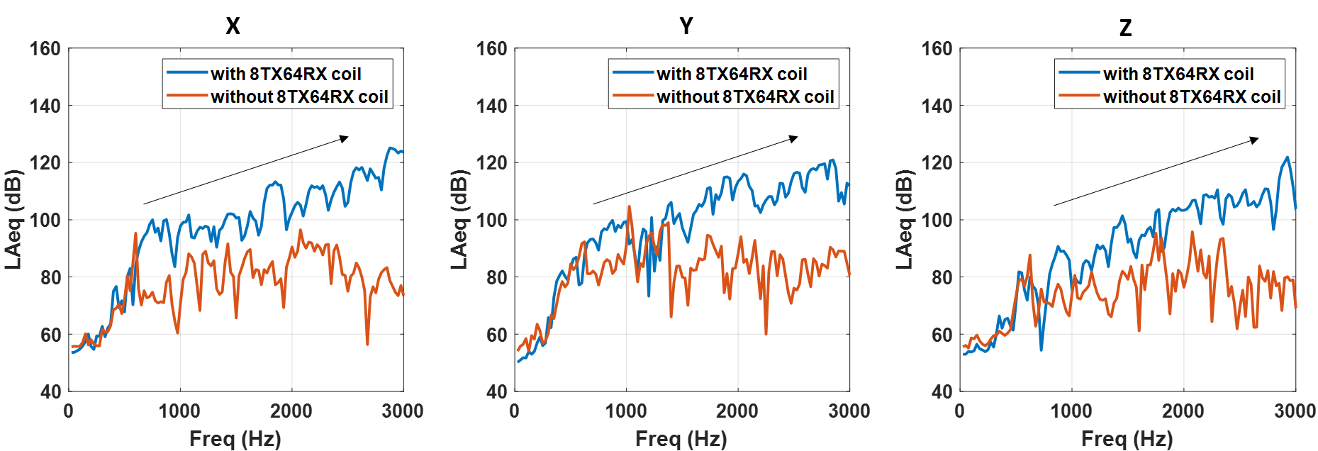
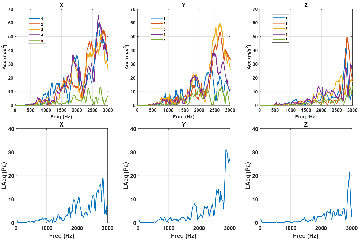
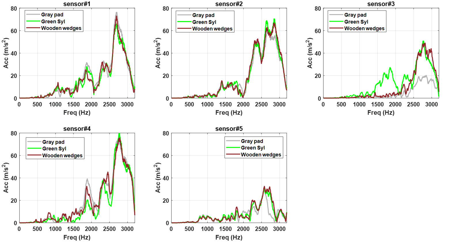
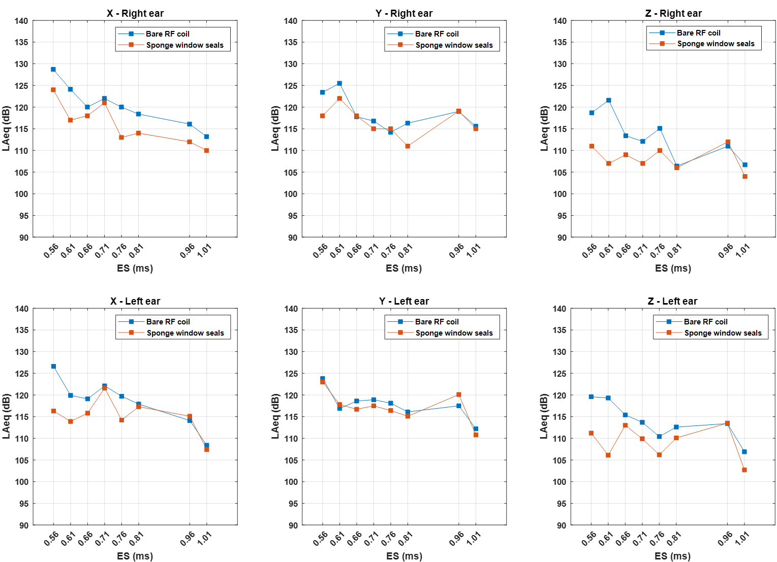
Figure 2 reports very different SPLs with and without the RF coil, with an increasing trend towards higher frequencies in the presence of the RF coil, which is consistent with eddy-currents (Faraday’s law) induced in the shield of the RF coil. Figure 3 shows the different sensor accelerations on the RF coil aligned with the sound measurements, where reasonable correlation can be observed, suggesting again that SPL originates mostly from the RF coil. The vibration of the table also was considerably lower without the RF coil than with the RF coil (data not shown). Lastly, Figure 4 shows the vibration measurements on the RF coil with the different support scenarios (pads or wooden wedges). The different configurations made little difference, indicating that mechanical coupling between the bed and the RF coil, and thus gradient coil vibration, is likely not responsible for most of the acoustic noise. The data of sensor 3 yet revealed some differences which were attributed to the corresponding contact levels between the accelerometer and the boreliner, thereby indicating that mechanical vibrations could be altered this way. Following this observation, the adhesive sponge window seals were placed to attempt establishing contact between the RF coil and the boreliner and disturb the vibrations. The acoustic measurements performed in vivo in these conditions, with EPI and at various ES are reported in Figure 5. Although there is not a systematic gain, up to 10 dB improvement could be observed at short ES.Discussion
Strong evidence was gathered to point towards eddy-current induced vibrations in the RF coil as the most important factor responsible for acoustic noise. Alterations of the mechanical vibrations of the RF coil were achieved by constraining its vibrations with the boreliner and allowed decreasing SPL by up to 10 dB.Conclusion
In our setup, acoustic noise is mostly induced by eddy-currents in the RF coil. The results pave the way for more investigations to reduce further acoustic noise in MRI.Acknowledgements
AROMA H2020 FET-Open (885876). U01-EB025162, U24-NS129949, R44-MH129278 (NIH).References
[1] Winkler et al. Magn Reson in Med 2017;78:1635-1645.
[2] Feinberg et al. In proceedings of the 2021 ISMRM and SMRT annual meeting, p 0562.
Figures