3727
Investigation of RF-induced Heating of Active Implantable Medical Device in the Vicinity of Fragmented Leads under 1.5T MRI1University of Houston, Houston, TX, United States, 2Micro Systems Engineering, Lake Oswego, OR, United States
Synopsis
Keywords: Safety, Safety
Motivation: Electrically short fragmented leads are sometimes left behind in the human body after the extraction of an active implantable medical device (AIMD). When a new AIMD is implanted near the fragmented leads, the radiofrequency (RF)-induced heating of the newly implanted AIMD could be altered.
Goal(s): Develop a method to evaluate the RF-induced heating of AIMD with fragmented leads in the vicinity.
Approach: We propose to use the electric field distribution which includes the presence of the fragmented leads with the AIMD transfer function model for RF-induced heating evaluation.
Results: The proposed method can effectively predict the RF-induced heating for AIMDs near fragmented leads.
Impact: It was observed that the RF-induced heating for AIMD system can be altered by the nearby fragmented leads.
Introduction
Some patients may require the implantation of a second AIMD after the first implanted AIMD is extracted due to either device functional failure or lead dysfunction. However, during the extraction of the original AIMD, some portion of the of the original lead may be left behind inside the human body. A functional AIMD, when implanted close to the electrically short lead fragment, may change the RF-induced heating of the functional AIMD. In this study, the impact of nearby electrically short lead fragments on the RF-induced heating of a functional AIMD was assessed using the transfer function models (TFM) of the functional AIMD developed with and without the fragmented lead in the vicinity 1.Method
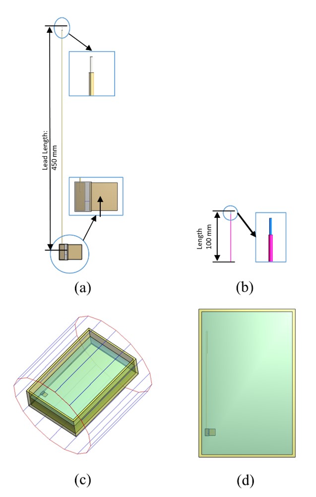
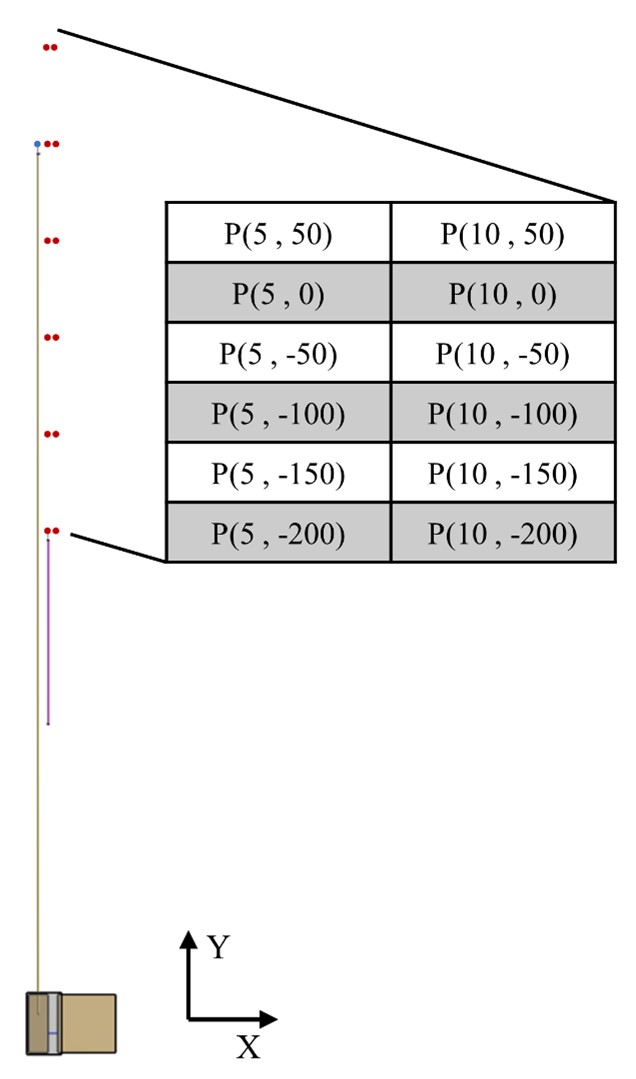
A simplified functional AIMD with 450 mm lead length and a 100 mm, electrically short fragmented lead were modeled as shown in Fig. 1(a)(b). The numerical simulations were conducted with the full-wave electromagnetic (EM) simulation software Sim4Life (SPEAG, Zurich, Switzerland). Devices were placed in the ASTM phantom filled to a depth of 9 cm with gelled saline (conductivity of 0.47 S/m, relative permittivity of 80), according to ASTM F21822. Fig. 1(c)(d) show the generic 1.5T G-32 RF birdcage coil and the placement of the devices inside the ASTM phantom. The fragmented lead was placed at various positions along the length of functional AIMD, at 2 different gap distances (5 mm, 10 mm) relative to it. The placement configurations are illustrated in Fig. 2. To evaluate the SAR near the lead tip of the AIMD by TF method, the incident E-fields (Etan(x)) along the AIMD trajectory were computed for the configurations described above with the fragmented lead removed from the phantom and functional AIMD remaining in the simulations. To numerically obtain the TF of the functional AIMD, a current edge source excitation was placed next to the tip of AIMD model, and current sensors along the lead body were used to collect the current profile, which yielded the unscaled TF. The scaling factor was obtained through the procedure described in §8.8 of ISO109743. The predicted SAR values were computed by using the numerically developed TF(x) and Etan(x) obtained from different configurations. To evaluate the accuracy of the TF method results, the EM simulations for those configurations were performed, and 1-g averaged SAR values at the lead tip were extracted under the limit of 2W/kg whole-body average SAR. Additionally, simulations of AIMD without fragmented lead were also conducted. Finally, the predicted SAR values computed with the TF method results were compared with the SAR values obtained with direct EM simulation.Results
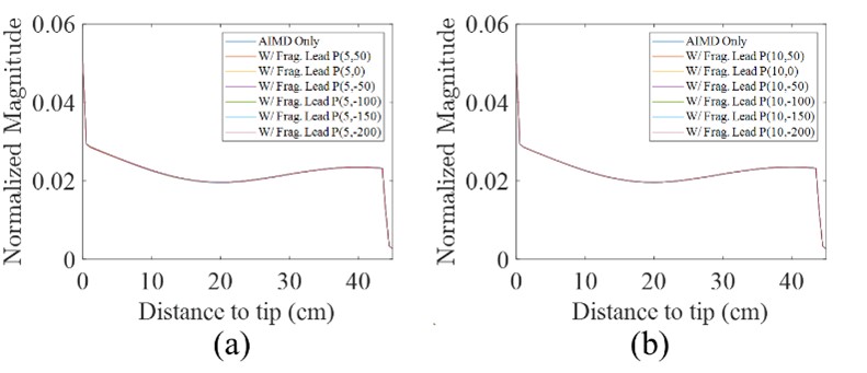
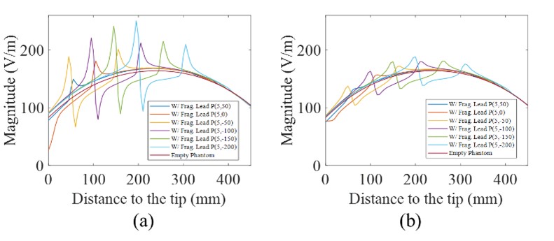
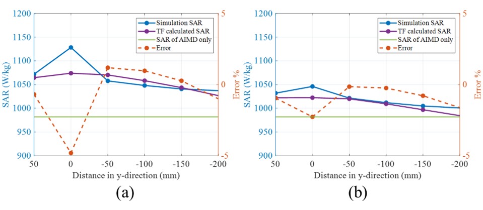
The numerically developed TFs are shown in Fig. 3. The magnitude of incident tangential E-field distributions is shown in Fig. 4. The SAR results of EM simulation and TF method and relative error are shown in Fig. 5.Discussion
From Fig. 3, the shape of the functional AIMD TFs in the presence of a nearby fragmented lead in all placement configurations are identical to the TF shape of the functional AIMD without the fragmented lead. This indicates that the TF of the AIMD is stable in the presence of the fragmented lead. However, the presence of the electrically short fragmented lead has significant influence on the incident tangential E-field as shown in Fig. 4, while its effect wanes with increasing gap distance. The SAR near the distal electrode of the functional AIMD can increase by up to 15% in the presence of even an electrically short fragmented lead. The absolute relative error between direct simulations and results obtained by the proposed approach is less than 5% for all configurations as shown in Fig. 5. The maximum absolute relative error occurs when the two tips are close to each other.Conclusion
The influence of a nearby electrically short, fragmented lead on the RF-induced heating of a functional AIMD was investigated in this study. The TFM of the lone standing functional AIMD was demonstrated to be valid even in the presence of a nearby electrically short fragmented lead. However, the predicted and simulated SAR at the electrode of the functional AIMD exhibited sensitivity to the localized perturbation of incident Etan induced by the nearby fragmented lead. SAR predictions obtained with the TF method, using perturbed Etan agreed well with the simulated SAR of the combined system for all position configurations. Hence, the TF approach may still be used to accurately predict RF-induced heating in the presence of fragmented lead.Acknowledgements
No acknowledgement found.References
1. Yang L, Mir Khadiza Akter, Guo R, Zheng J, Chen J. Evaluation of MRI RF-induced for Active Implantable Medical Implants in the vicinity of other implantable devices. IEEE/MTT-S International Microwave Symposium - IMS 2023, San Diego, CA, USA, 2023, pp. 851-854.
2. Standard test method for measurement of radio frequency-induced heating on or near passive implants during magnetic resonance imaging. ASTM F2182-19e2. (2019).
3. Assessment of the Safety of Magnetic Resonance Imaging for Patients with an Active Implantable Medical Device. International Organization for Standardization (ISO), ISO/TS 10974, 2018.
Figures