3726
Reduction of RF-heating on bilateral DBS leads using two channel RF-shimming on 3T MRI1Department of Imaging, Radboud University Medical Center, Nijmegen, Netherlands, 2Donders Institute for Brain, Cognition and Behaviour, Department of Neurosurgery, Radboud University Medical Center, Nijmegen, Netherlands, 3Magnetic Detection and Imaging group, TechMed Centre, University of Twente, Enschede, Netherlands
Synopsis
Keywords: Safety, Safety, Deep Brain Stimulation; Parallel Transmission
Motivation: Bilateral deep brain stimulation (DBS) surgery would benefit from safe intraoperative 3T MRI using conventional scanners.
Goal(s): Our goal was to develop a method to determine patient-specific safety constraints to scan a bilateral lead configuration with minimal RF-heating, by minimizing RF-induced currents at maximal B1.
Approach: We scanned a phantom with two leads in different configurations, measured local heating and determined the transimpedance.
Results: We could determine the phantom-specific safety constraints and find a low-SAR sequence meeting the constraints, after optimizing the two channel RF-shimming to minimize RF-heating by minimizing RF-induced currents at maximal B1.
Impact: The proposed method can be used to minimize heating of a bilateral lead configuration and estimate patient-specific safety constraints, but further research has to be conducted to be able to use it during deep brain stimulation surgery.
Purpose
Deep brain stimulation (DBS) is a well-established surgical treatment to relieve symptoms of many neurological disorders, including Parkinson’s disease. Accurate positioning of the leads in the subthalamic nucleus (STN) renders 3T MRI the preferred clinical modality for providing intraoperative feedback. Currently, most DBS systems are not yet labeled at 3T due to the increased risk of RF-heating, and this holds in particular for partially implanted DBS systems in the intraoperative setting. This becomes increasingly limiting on 3T protocols in DBS patients due to increasing regulatory requirements and associated costs of labelling.A potential solution to manage RF-safety in DBS configurations is parallel transmission, where two-channel RF-shimming has been shown to be able to mitigate the RF-induced current on single-lead configurations.1,2 Clinical DBS implantation typically involves bilateral lead placement, however, for which the two degrees of freedom (relative RF amplitude and phase) are known to be insufficient for complete nulling of both currents simultaneously.3,4 In this study, we explore the potential of minimizing the RF-induced currents on both leads with two-channel RF-shimming, while maximizing the available B1+, and assess the potential of performing a low-SAR protocol based on the obtained patient-specific safety constraints.
Methods
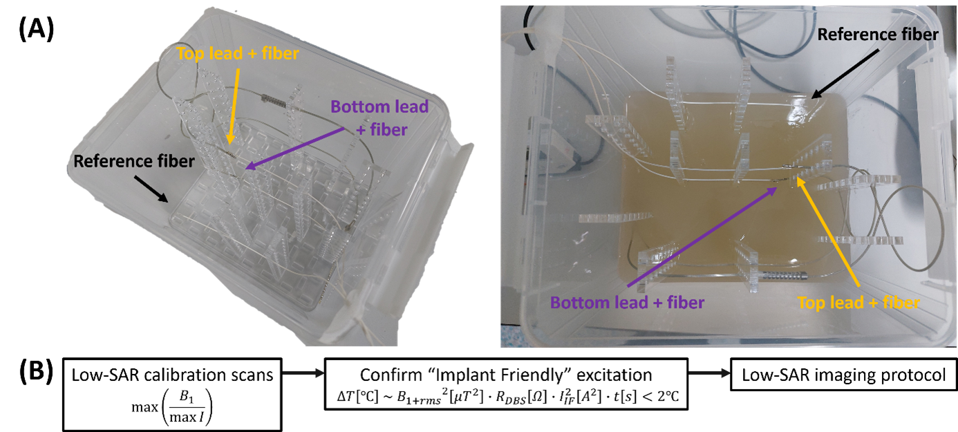
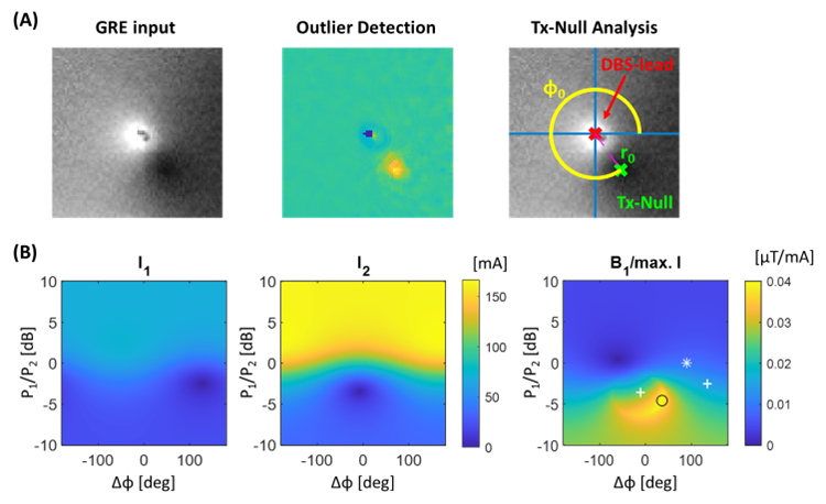
A phantom (30g/L agar powder; 2g/L NaCl; 16×13×12cm), see figure 1A, mimicking the brain, including electrical conductivity and thermodynamics, containing two parallel, centrally placed directional DBS leads (Vercise Cartesia Directional, DB-2202, Boston Scientific, Marlborough, MA) was created. To record the heating, three fiber-optic temperature probes (OTP-M series, Opsens, Quebec City, QC) were used (one at each tip, one as reference).The phantom was scanned following the workflow described in figure 1B. First, low-SAR channelwise GRE and B1+-data is acquired similarly to Eryaman, et al.2 The DBS lead position and Tx-Null artefact are characterized by an outlier detection procedure, yielding quantitative values for the channelwise induced current, as shown in figure 2A. The combined implant friendly (IF) mode was then determined by maximizing the B1+ divided by the maximum lead current I, as shown in figure 2B. An additional low-SAR GRE and B1+-dataset is acquired using these excitation settings for confirmation.
Local heating was measured using fiber-optic temperature sensors directly adjacent to the lead electrodes in each of their individual IF mode, as well as the combined (IF) mode and quadrature mode (time = 3:04, FA = 110°, TR = 2600ms, TE = 110ms, slices = 26, slice thickness = 2mm). Following the method of Sadeghi-Tarakameh, et al.5, the remaining induced current I was translated to a patient-specific safety constraints, limiting the temperature increase to 2°C, using the transimpedance RDBS.6
Results
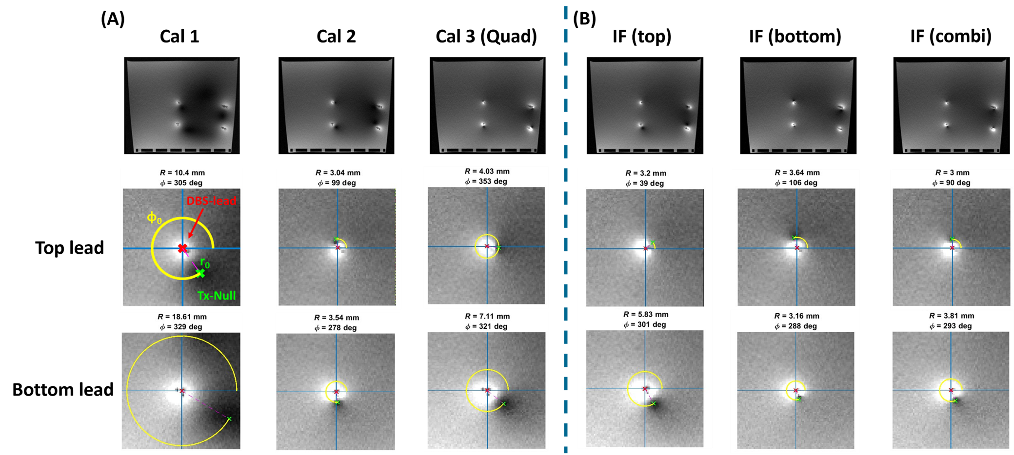
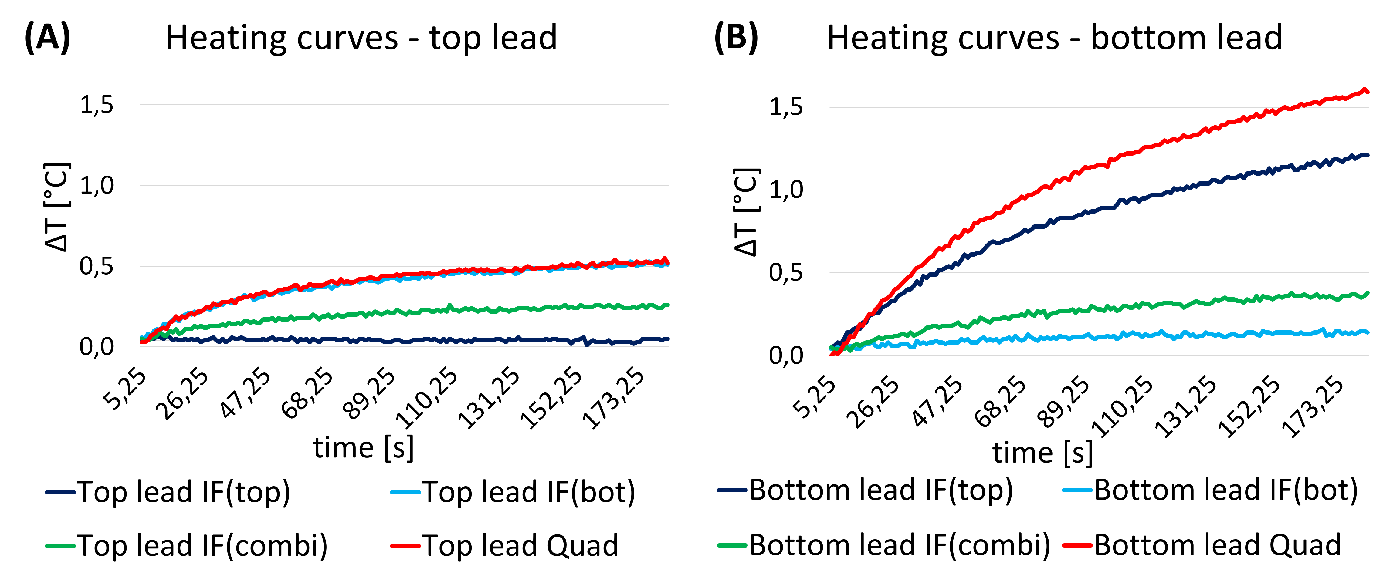
The 2D GRE calibration scans (Cal 1-3), shown in figure 3A, were used to determine the top, bottom and combined IF mode. As shown in figure 3B, the Tx-null artifacts of both leads have a similar magnitude in the IF combi mode, indicating equality of the induced current.Figure 4 shows the heating curves, induced by the TSE sequence, for the top lead (A) and the bottom lead (B) of the IF (top), IF (bottom), IF (combi) and quadrature mode, as a reference, indicating that the IF combi mode results in minimal heating in both leads. This configuration limits the temperature rise to 0.4°C in both leads.
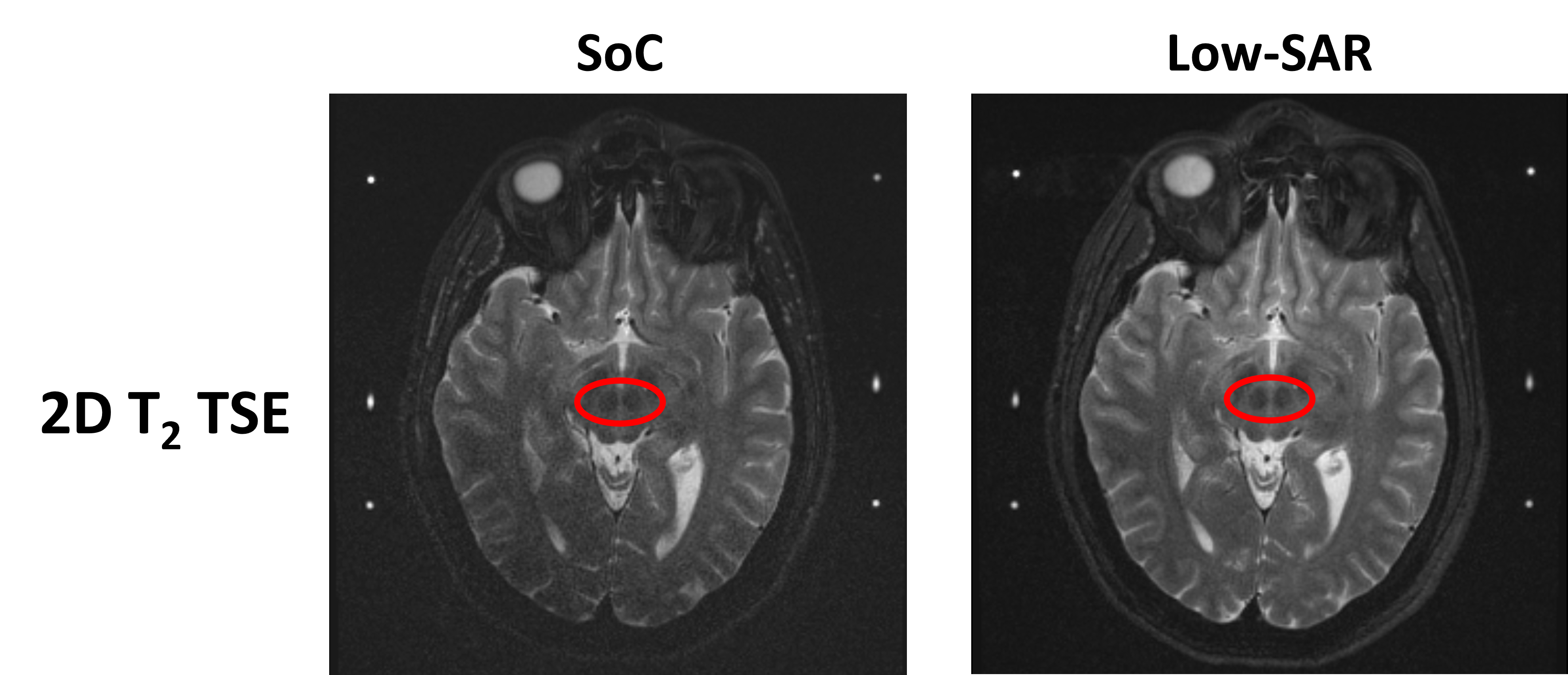
From the obtained phantom-specific transimpedance RDBS and the remaining induced currents I for both leads in IF combi mode, the B1+rms-limit of the top lead was determined to be 0.81µT and of the bottom lead 0.65µT, complying with the B1+rms = 0.60µT of the low-SAR protocol, in contrary to the Standard of Care (SoC) protocol with a B1+rms of 2.40µT. Images aquired with both protocols are shown in figure 5.
Discussion
To translate the phantom study to patients, reliability of the patient-specific safety constraints should be increased by including error margins and scanning more orientations. Also further studies should be conducted, starting with a patient-like phantom with the leads implanted in a patient-like manner (angulated and with the tips closer together), and concluding with a cadaver study, to provide the most realistic setting with correct electrical conductivity, thermodynamics and permittivity.In the end, the created low-SAR protocol will not be one-size fits all: the scan time can be reduced by increasing the TR without influencing the T2-contrast.
Conclusion
In this study, we have explored the potential of minimizing the RF-induced currents on a bilateral DBS configuration using two-channel RF-shimming. We showed that the combined IF mode produces the least heating in both leads, were able to determine the phantom-specific B1+rms-limit and create a complying low-SAR protocol showing comparable image quality to the SoC protocol.Acknowledgements
We would like to thank Kristian Overduin, Andor Veltien and Dagmar Grob from the Radboudumc for their contribution to the project, and Yigitcan Eryaman of the CMRR for helpful discussions.References
- Eryaman Y, Turk EA, Oto C, et al. Reduction of the radiofrequency heating of metallic devices using a dual-drive birdcage coil. Magn Reason Med. 2013;69(3):845-852.
- Eryaman Y, Kobayashi N, Moen S, et al. A simple geometric analysis method for measuring and mitigating RF induced currents on Deep Brain Stimulation leads by multichannel transmission/reception. NeuroImage. 2019;184:658‐668.
- Etezadi-Amoli M, Stang P, Kerr A, et al. Controlling radiofrequency-induced currents in guidewires using parallel transmit. Magn Reason Med. 2015;74(6):1790-1802.
- Sadeghi-Tarakameh A, DelaBarre L, Zulkarnain NIH, et al. Implant-friendly MRI of deep brain stimulation electrodes at 7 T. Magn Reason Med. 2023;90:2627-2642.
- Sadeghi-Tarakameh A, Zulkarnain NIH, He X, et al. A workflow for predicting temperature increase at the electrical contacts of deep brain stimulation electrodes undergoing MRI. Magn Reason Med. 2022;88:2311-2325.
- Finelli DA, Rezai AR, Ruggieri PM, et al. MR Imaging-Related Heating of Deep Brain Stimulation Electrodes: In Vitro Study. Am J Neuroradiol. 2002;23(10):1795-1802.
Figures