3725
Safety of Intraoral Coils: Accuracy of Simulations1Division of Medical Physics, Department of Diagnostic and Interventional Radiology, University Medical Center Freiburg, Faculty of Medicine, University of Freiburg, Freiburg, Germany
Synopsis
Keywords: Safety, Safety, dental MRI, RF safety, intraoral coil, simulation
Motivation: In dental applications intraoral coils (IOCs) offer higher SNR than external surface coils, but the details of RF-induced heating of an intraoral coil dependent on many factors such as coil size, shape, incident E-field, surrounding tissue, and acquisition protocol.
Goal(s): This study investigates the effect of anatomical model complexity on SAR simulations for IOCs.
Approach: Numerical simulations were compared to electric field mapping and temperature measurements to evaluate RF-induced heating of various IOCs.
Results: RF heating and SAR simulations of IOCs can be performed with limited tissue models, but the required complexity of the tissue model depends on the coil type.
Impact: The complexity of numerical simulations can be reduced to limited tissues while maintaining accuracy of SAR estimation to determine the safety of intraoral coils through hotspot detection.
Introduction
The use of dedicated radio frequency coils1-3 enables the application of MRI for dental pathologies in endodontics4,5, orthodontics6 and craniomaxillofacial surgery7. Intraoral coils (IOCs) improve the signal to noise ratio (SNR) and, thus, offer dental images with higher spatial resolution8-11. However, the electrically conducting structures in the IOCs can lead to potentially dangerous RF induced heating similar to implants12-13. Detailed computational models of the human body14 allow performing electromagnetic simulations with very high spatial resolution in and around the oral cavity. In this study, we evaluated E-field and SAR simulations in anatomical models using a reduced number of tissues (tissue clustering and averaging)15 arranged according to their electrical properties.Methods
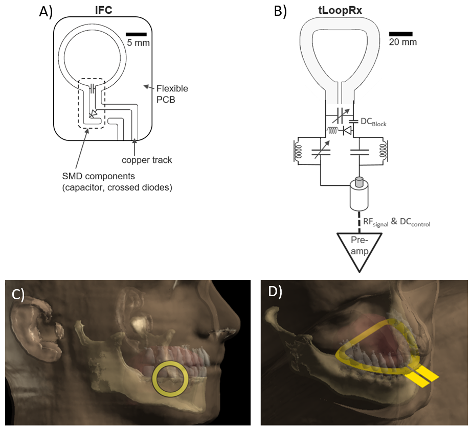
To evaluate RF-induced heating of IOCs first hotspots were detected, and then temperature measurements were performed at these hotspots.Dental coils: Two different types of intraoral coils were studied (Fig. 1): An intraoral inductively coupled flexible coil (IFC) (ø=15 mm, track width=2mm on flexible PCB with a width of 0.2mm)11 and a transverse loop coil (tLoopRx) constructed out of a 1mm-thick copper plate with a dental bite shape9-10. Both coils had a disposable and water-tight plastic cover.
Numerical simulations: FDTD simulations (Sim4Life, ZMT, Zürich) of the IOCs (Fig. 1C-D) and the Tx body coil were performed to obtain tangential electric fields and SAR distributions at 3T (123.2 MHz). Different anatomical models were used to compare E-field and SAR distribution. First, simulations were performed for a homogenous head with an average tissue conductivity (σ=0.61 S/m) and permittivity (εr=79.2). Then, a detailed head model (Virtual Population, Duke, It’Is, Zürich) with 37 tissue types was utilized with individual conductivities and dielectric properties14. From this, a model with reduced complexity was calculated by tissue clustering15 resulting in 4 different tissue types: soft tissue (σ=0.95 S/m, εr=54), bone (σ=0.05 S/m, εr=12), fat (σ=0.11 S/m, εr=11) and fluid (σ=2.1 S/m, εr=80). In the simulations, the intraoral coils were placed in the anatomical model, and the mandible was centered at the isocenter of the body coil.
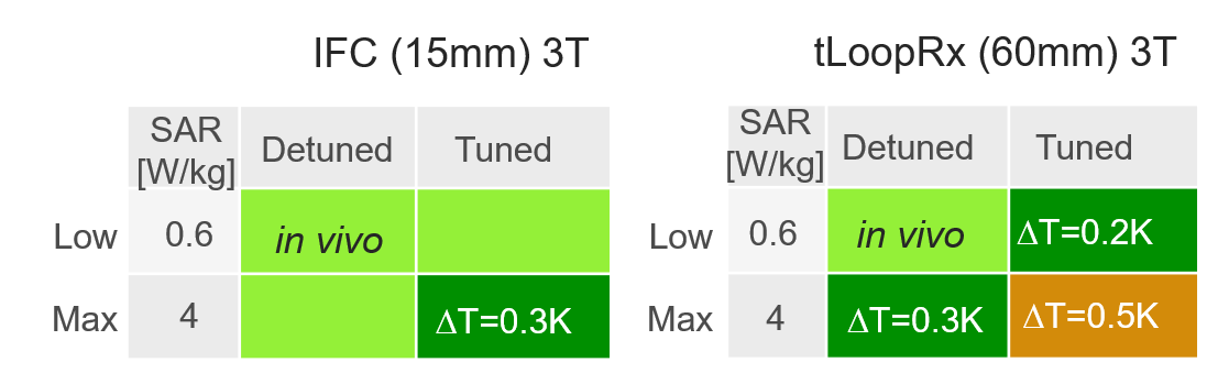
Measurements: E-field maps were measured over the IFC and tLoopRx surface with an electro-optic sensor (EOS) for hotspot detection during RF excitation at 123.2 MHz16. Temperature measurements were performed with both coils at a clinical 3T system (PrismaFit, Siemens) using 4 fiber optical temperature sensors (FOTEMP, Optocon AG) at the hotspots inside a HEC-gel phantom17 with (σ=0.61 S/m, εr=79.2). Two pulse sequences were applied with whole-body SAR of 0.6 W/kg (3D T2-weighted SPACE sequence) and 4 W/kg (RF only) over 360s for tuned and detuned coils11.
Results
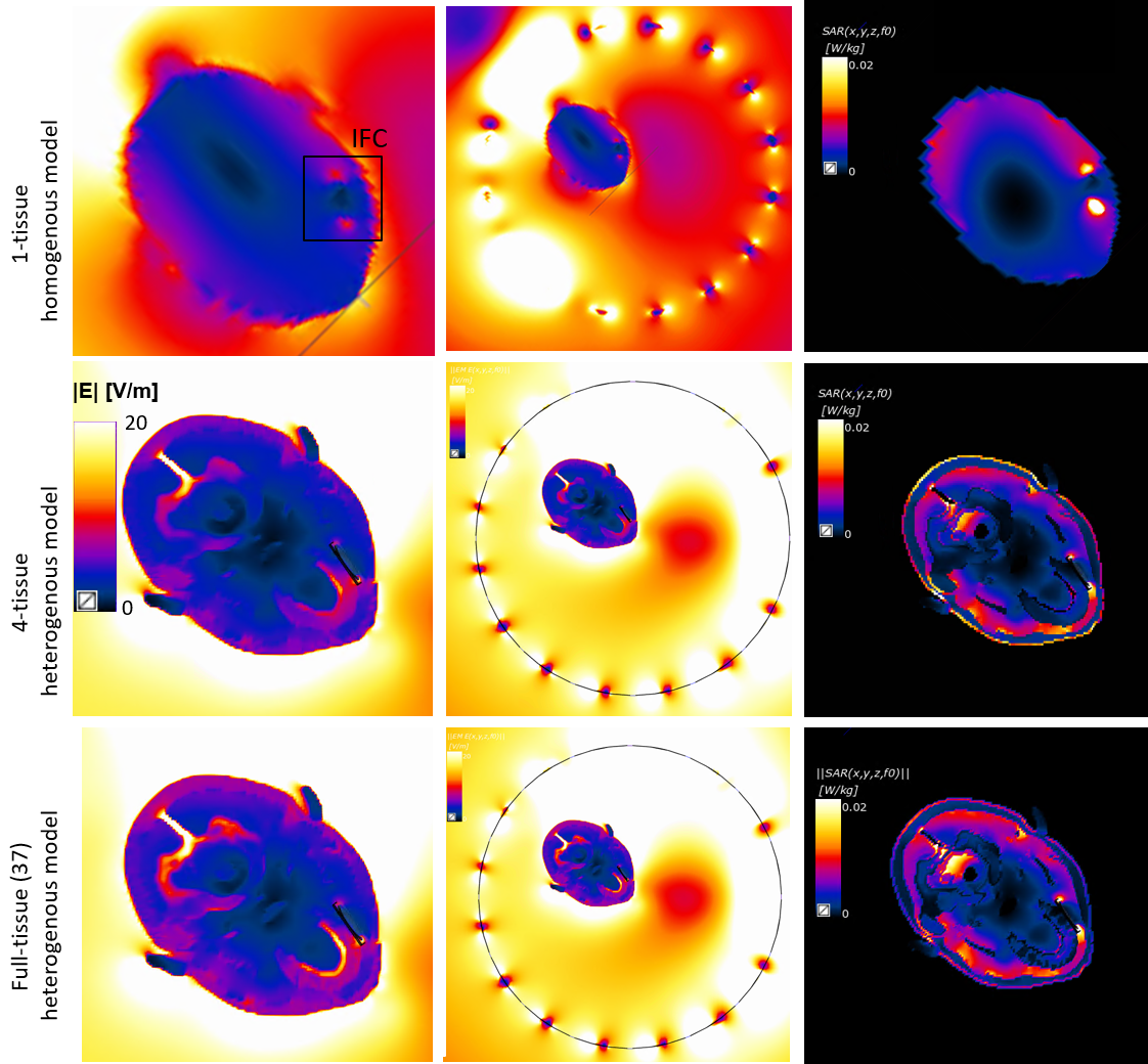
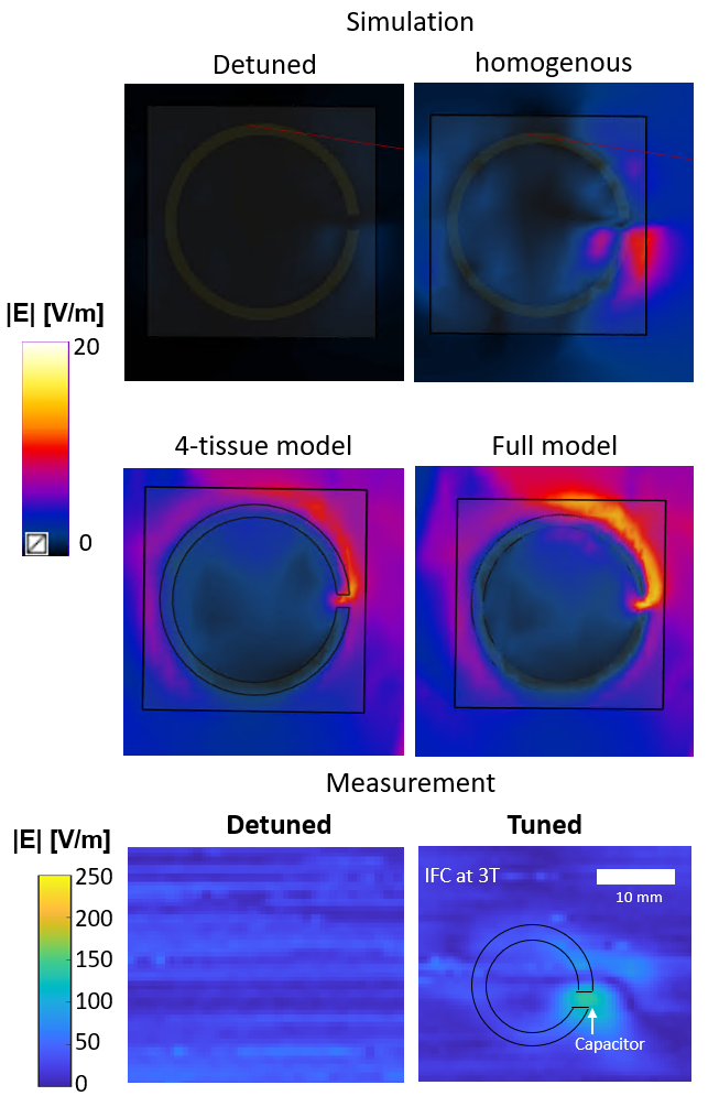
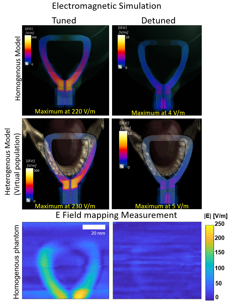
Hotspot locations can be seen for all model types adjacent to IFC (Fig. 2 first column). E-field amplitudes differ between the homogenous and the heterogenous model. 1-tissue model has a maximum value of 12 V/m in the vicinity of the lumped elements, which increases to 17.5 V/m for the 4-tissue model and is highest (20 V/m) for the full-tissue model. Additional hotspots are visible around the maxilla arch and the falx cerebri (posterior brain). Higher local SAR of 0.02 W/kg is concentrated around the coil (1-tissue model), while the heterogeneous models display a more distributed SAR of 0.05 to 0.18 W/kg in the coil vicinity and at the hotspots around coil and brainstem. Fig. 3 shows a close-up simulation of the coil surface with the electric field distribution for tuned and detuned states.The simulation of the tuned tLoopRx in the homogenous model has a peak E-field magnitude of 220 V/m at the feed port comparable to 4-tissue and full-model (Fig. 4). The E-field amplitude decreases symmetrically along the coil conductor with increasing distance to the feed port. This coincides with the measured electric field for spatial distribution and magnitude. Detuned coils show no relevant SAR increase. Temperature measurements (Fig. 5) yield a maximum temperature increase for tuned tLoopRx with 0.5K for the maximum SAR sequence which is in line with the simulations.
Discussion
Simulations with the homogeneous model give comparable hotspot locations as the measurements. IFC simulations showed a 30% difference between homogenous and heterogenous simulations, and additional hotspot locations were found. The simplified 4-tissue model has an error below 10% to estimate E-field and SAR magnitude while spatial mapping remains the same as the full model. Overall, this study demonstrated the feasibility to assess the RF-induced heating risk of IOCs through E-field and SAR simulations in anatomical models using a reduced number of tissues that coincide with measurement results.Acknowledgements
No acknowledgement found.References
1. Prager M et al. Dental MRI using a dedicated RF-coil at 3 Tesla. J. Cranio-Maxillofacial Surg. 2015;43:2175–2182
2. Sedlacik J et al. Optimized 14+1 receive coil array and position system for 3D high-resolution MRI of dental and maxillomandibular structures. Dentomaxillofacial Radiol. 2015;45:2–7
3. Gradl J et al. Application of a Dedicated Surface Coil in Dental MRI Provides Superior Image Quality in Comparison with a Standard Coil. Clin. Neuroradiol. 2017;27:371–378
4. Ariji Y, Ariji E, Nakashima M, Iohara K. Magnetic resonance imaging in endodontics: a literature review. Oral Radiol. 2018;34:10–16
5. Leontiev W, Bieri O, Madörin P, et al. Suitability of Magnetic Resonance Imaging for Guided Endodontics: Proof of Principle. J. Endod. 2021;47:954–960
6. Juerchott A et al. In vivo comparison of MRI- and CBCT-based 3D cephalometric analysis: beginning of a non-ionizing diagnostic era in craniomaxillofacial imaging? Eur. Radiol. 2020;30:1488–1497
7. Juerchott A et al. In vivo reliability of 3D cephalometric landmark determination on magnetic resonance imaging: a feasibility study. Clin. Oral Investig. 2020;24:1339–1349
8. Ludwig U, et al. "Dental MRI using wireless intraoral coils." Scientific reports 6.1 (2016): 1-11
9. Ozen AC, et al. "Design of an Intraoral Dipole Antenna for Dental Applications." IEEE Transactions on Biomedical Engineering (2021).
10. Idiyatullin D et al. Intraoral approach for imaging teeth using the transverse B1 field components of an occlusally oriented loop coil. Magn Reson Med. 2014;72:160–165.
11. Tesfai AS, et al. "Inductively Coupled Intraoral Flexible Coil for Increased Visibility of Dental Root Canals in Magnetic Resonance Imaging." Investigative Radiology (2021).
12. Shellock F. G. et al. Radiofrequency Energy-Induced Heating During MR Procedures: A Review, J. Magn. Reson. Imaging, vol. 12, no. 1, pp. 30–36, Jul. 2000
13. Yeung C. J. et al. RF heating due to conductive wires during MRI depends on the phase distribution of the transmit field,” Magn. Reson. Med., vol. 48, no. 6, pp. 1096–1098, 2002
14. Gosselin, M.-C. et al. Development of a new generation of high-resolution anatomical models for medical device evaluation: the Virtual Population 3.0. Phys. Med. Biol. 59(18), 5287 (2014)
15. de Buck et al. "An investigation into the minimum number of tissue groups required for 7T in‐silico parallel transmit electromagnetic safety simulations in the human head." Magnetic Resonance in Medicine 85.2 (2021): 1114-1122.
16. Reiss S.,Bitzer A., and Bock M. An optical setup for electric field measurements in MRI with high spatial resolution, Phys. Med. Biol., vol. 60, no. 11, pp. 4355–4370, Jun. 2015.
17. American Society for Testing and Materials International, “Designation: ASTM F2182-19, Standard Test Method for Measurement of Radio Frequency Induced Heating On or Near Passive Implants During Magnetic Resonance Imaging,” West Conshohocken, PA, 2019.
Figures