3723
Influence of Body Coil Drive Mode on the MR Safety of Interventional Devices1Division of Medical Physics, Department of Radiology, Medical Center - University of Freiburg, University of Freiburg, Freiburg, Germany, 2Interventional MR Clinical R&D Institute, Ankara University, Ankara, Turkey, 3National MR Research Center (UMRAM), Bilkent University, Ankara, Turkey
Synopsis
Keywords: Safety, Safety, Low Field, RF-induced heating, Interventional
Motivation: RF-induced heating of interventional devices is reduced at lower magnetic fields, but dangerous heating conditions can still occur during MR-guided interventions.
Goal(s): To investigate the effect of body coil drive mode on RF-induced heating of interventional devices at 0.55T and 1.5T.
Approach: Numerical simulations, E-field, transfer function and temperature measurements are used to evaluate the dependency of RF-induced heating of commonly used interventional devices on the phase and amplitude settings of body coil ports.
Results: RF-induced heating can be reduced using individually adapted body coil drive modes.
Impact: Dual-drive body coil technology can be used to generate implant-friendly electromagnetic fields, which can enable safe use of clinical intravascular devices during MR-guided interventions at 0.55T and 1.5T.
Introduction
RF-induced heating of implants and devices in the MRI is a result of the coupling of external electromagnetic (EM) transmit fields with elongated metallic structures[1], [2]. The heating depends on the incident E field[3], EM properties of device and surrounding tissue, input impedance[4], [5] and insertion length[6], [7]. Low-field MRI systems (e.g., at 0.55T) are expected to cause less heating than 1.5T or 3T systems[8]; however, since the heating depends on the target organ and patient size[7], additional measures are needed to reduce heating of devices during interventions. To use existing interventional devices, the MRI must be modified to be ‘device-safe’. Device-safe MRI methods are mostly based on modification of the transmit (Tx) coil’s EM fields[9]–[16] or RF pulses[17] using parallel Tx or create a zero-E field plane of a linearly polarized birdcage coil[9], [18]–[20]. Other methods include design of low-specific-absorption-rate (SAR) protocols[21] and low field systems [8]. A numerical analysis of RF exposure on implant heating was also investigated in[22]. As 2-channel parallel transmit technologies have become available even for the birdcage body coils in conventional MR systems at 1.5T and 3T, in this study we investigate their effect on RF-induced heating of interventional devices at 0.55T and 1.5T.Methods
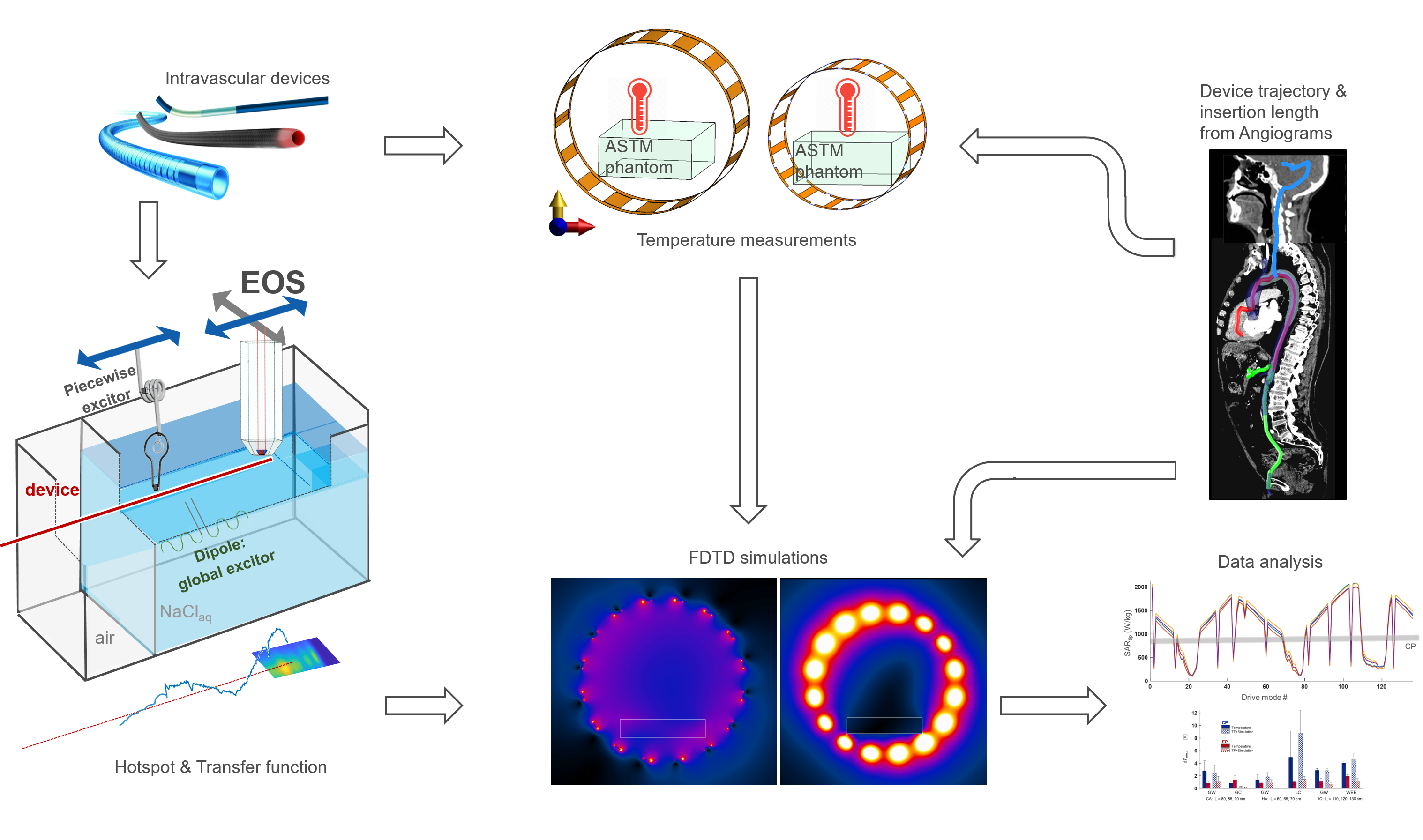
General workflow for the numerical simulation and measurements is presented in Fig. 1.Test setup: A modified Tier-3 approach was applied [7], [23], where high resolution E-field maps were measured for hot-spot detection during RF excitation at fLarmor(0.55T)=23.66MHz, fLarmor(1.5T)=63.85MHz, and TF measurements were performed with an electro-optic sensor (EOS) [24] at the hot spot [6]. TFs were calibrated using various dipole excitation patterns [23]. An RF test-bench was constructed for temperature measurements in 0.55T (Ø=790mm, Length=500mm) and 1.5T (Ø=790mm, Length=500mm) quadrature body coils. In addition to the circularly polarized (CP) mode, two elliptically polarized (EP) modes were generated by a variable phase shift between the feed ports.
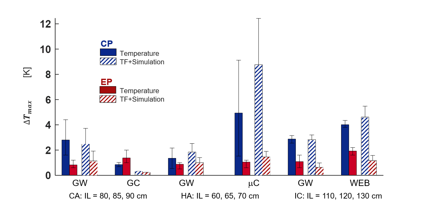
Device selection: Realistic device trajectories for coronary artery (CA), hepatic artery (HA), and intracranial (IC) catheterizations were obtained [7]. Temperature measurements were performed using a fiber-optic temperature sensor (FOTEMP, Optocon) in a gel phantom (30g/L-HEC&1.55g/L-NaCl[25], εr = 82.5/81.1, σ = 0.63/0.64 S/m @23.7/63.9MHz). For CA, HA, and IC devices, insertion lengths of [80,85,90]cm, [60,65,70]cm, and [110,120,130]cm were tested. For CA and HA engagement, two guidewires(GW), a guiding-catheter(GC), and a microcatheter-(uC) were selected. In addition to a GW, an intrasaccular flow disruptor for aneurysm cavities was evaluated [26], [27].
Numerical simulations: Body coils were simulated using FDTD (Sim4Life, ZMT, Zürich), and tangential E fields along the trajectories were extracted for various relative amplitude&phase settings of the body coil feed ports. EP modes with minimum B1+ homogeneity (i.e., maximum deviation of 20%) were identified. The RF input power was scaled to achieve mean B1+ of 11.75µT within the center of the phantom.
Results
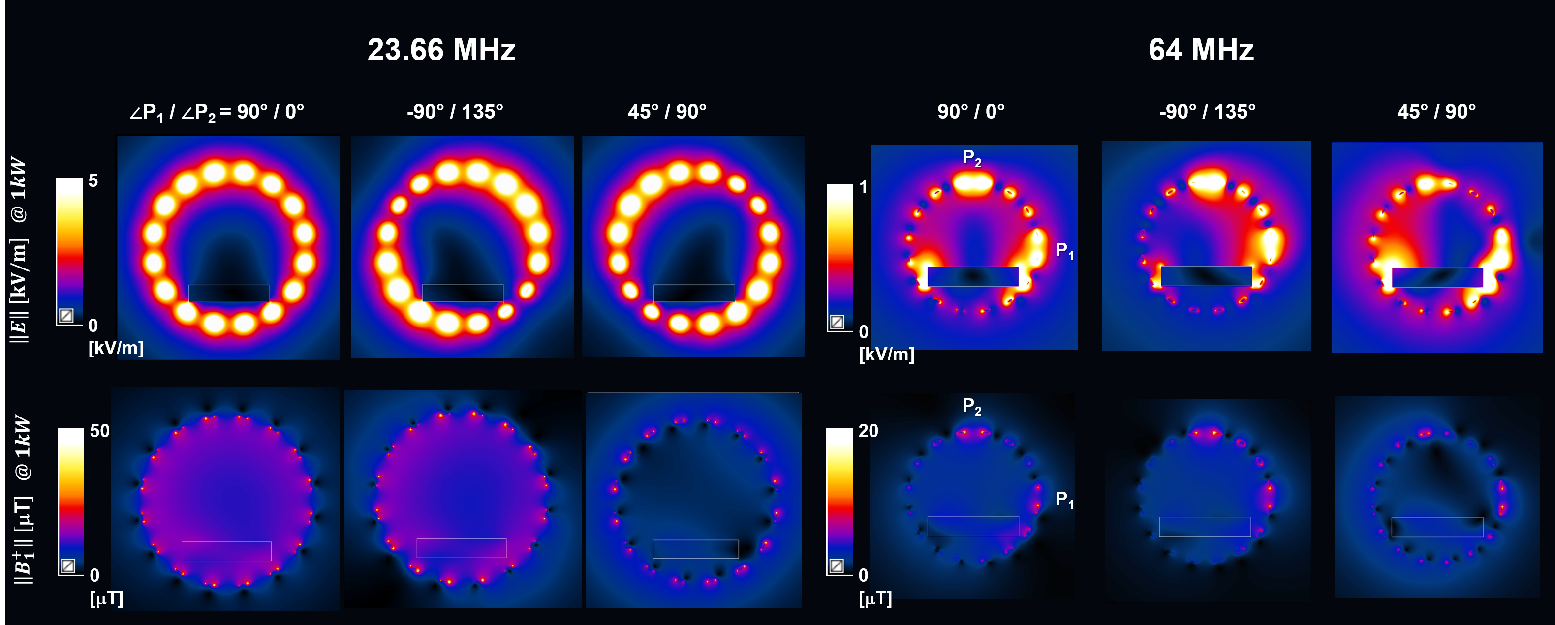
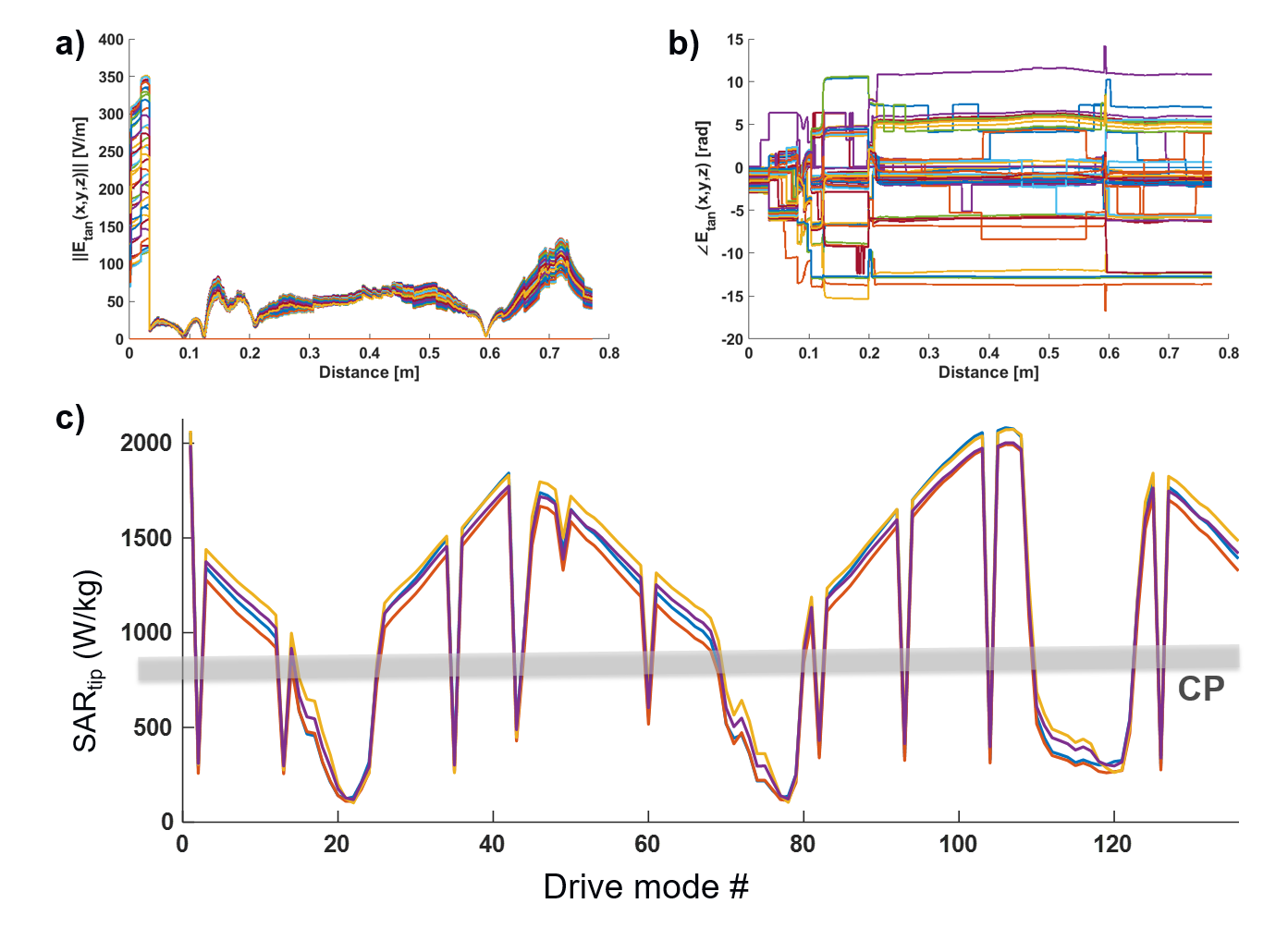
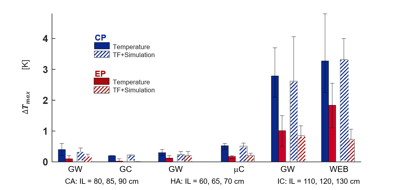
Consistent with previous findings [23], hotspot locations were identical at 0.55T and 1.5T. Simulated E fields are shown in Fig. 2 for the CP and two EP modes for 0.55T & 1.5T. E field phases and amplitudes along the device trajectories are plotted for the drive modes with minimum B1+ homogeneity in Fig. 3 together with estimated SAR in comparison to the CP mode. Although EP modes exists with an up to 4-fold lower SAR than the CP mode, also modes with 2.5-fold higher SAR have been observed (Fig. 3c). Temperature measurements and TF-based temperature estimations at 0.55T (Fig. 4) and at 1.5T (Fig. 5) show a strong dependency on the insertion length of the device. IC catheterization has higher average temperature increases (ΔTmax = 4.4K) than CA (ΔTmax = 0.8K) and HA (ΔTmax = 0.7K) at 0.55T, as during an IC the IL approaches the resonant length. At 0.55T, temperature rises were consistently lower than 1.5T except for the HA case. TF-based temperature rise and RF-induced heating measurements were comparable, except for 1.5T, where up to 100% differences are observed. Differences between CP and EP modes were higher in simulations than in the measurements, as only the phase difference was adjusted in the measurements.Discussion
Using optimized drive modes, RF-induced device heating can be significantly reduced during an intervention. Parallel transmit options for body coils are valuable also at low fields, where B1 shimming is usually not required. Note, that EP modes selected in FDTD simulations were not identical, since EP mode for temperature measurements were empirically selected by adjusting the phase of one port using different cable lengths. Inconsistencies between simulation and measurement at 1.5T are due to inaccuracies in our model, which will be improved in future versions.Acknowledgements
Technical support by M. Malzacher, J. Nistler, M. Leghissa, B. Kraus of Siemens Healthineers; and grant support by BMBF (13GW0356B), and DFG under CRC 1425 (Project P15) are gratefully acknowledged.
The mention of commercial products, their sources, or their use in connection with material reported herein is not to be construed as either an actual or implied endorsement of such products by the authors or their institutions.
References
[1] F. G. Shellock, “Radiofrequency Energy-Induced Heating During MR Procedures: A Review,” J. Magn. Reson. Imaging, vol. 12, no. 1, pp. 30–36, Jul. 2000, doi: 10.1002/1522-2586(200007)12:1<30::AID-JMRI4>3.0.CO;2-S.
[2] C. J. Yeung, R. C. Susil, and E. Atalar, “RF heating due to conductive wires during MRI depends on the phase distribution of the transmit field,” Magn. Reson. Med., vol. 48, no. 6, pp. 1096–1098, 2002, doi: 10.1002/mrm.10310.
[3] S.-M. Park, R. Kamondetdacha, and J. A. Nyenhuis, “Calculation of MRI-induced heating of an implanted medical lead wire with an electric field transfer function,” J. Magn. Reson. Imaging, vol. 26, no. 5, pp. 1278–1285, Nov. 2007, doi: 10.1002/jmri.21159.
[4] A. C. Özen, T. Lottner, and M. Bock, “Safety of active catheters in MRI: Termination impedance versus RF‐induced heating,” Magn. Reson. Med., vol. 81, no. 2, pp. 1412–1423, Feb. 2019, doi: 10.1002/mrm.27481.
[5] A. C. Özen, B. Silemek, T. Lottner, E. Atalar, and M. Bock, “MR safety watchdog for active catheters: Wireless impedance control with real‐time feedback,” Magn. Reson. Med., vol. 84, no. 2, pp. 1048–1060, Aug. 2020, doi: 10.1002/mrm.28153.
[6] T. Lottner, S. Reiss, A. Bitzer, M. Bock, and A. Caglar Ozen, “A Transfer Function Measurement Setup With an Electro-Optic Sensor for MR Safety Assessment in Cascaded Media,” IEEE Trans. Electromagn. Compat., vol. 63, no. 3, pp. 662–672, Jun. 2021, doi: 10.1109/TEMC.2020.3040756.
[7] A. C. Özen et al., “RF-induced heating of interventional devices at 23.66 MHz,” Magn. Reson. Mater. Physics, Biol. Med., vol. 36, no. 3, pp. 439–449, May 2023, doi: 10.1007/s10334-023-01099-7.
[8] A. E. Campbell-Washburn et al., “Opportunities in Interventional and Diagnostic Imaging by Using High-Performance Low-Field-Strength MRI,” Radiology, vol. 293, no. 2, pp. 384–393, Nov. 2019, doi: 10.1148/radiol.2019190452.
[9] Y. Eryaman, B. Akin, and E. Atalar, “Reduction of implant RF heating through modification of transmit coil electric field,” Magn. Reson. Med., vol. 65, no. 5, pp. 1305–1313, May 2011, doi: 10.1002/mrm.22724.
[10] Y. Eryaman, E. A. Turk, C. Oto, O. Algin, and E. Atalar, “Reduction of the radiofrequency heating of metallic devices using a dual-drive birdcage coil,” Magn. Reson. Med., vol. 69, no. 3, pp. 845–852, Mar. 2013, doi: 10.1002/mrm.24316.
[11] N. Gudino et al., “Parallel transmit excitation at 1.5 T based on the minimization of a driving function for device heating,” Med. Phys., vol. 42, no. 1, pp. 359–371, Jan. 2015, doi: 10.1118/1.4903894.
[12] M. Etezadi-Amoli, P. Stang, A. Kerr, J. Pauly, and G. Scott, “Controlling radiofrequency-induced currents in guidewires using parallel transmit,” Magn. Reson. Med., vol. 74, no. 6, pp. 1790–1802, Dec. 2015, doi: 10.1002/mrm.25543.
[13] L. Winter et al., “Parallel transmission medical implant safety testbed: Real‐time mitigation of RF induced tip heating using time‐domain E‐field sensors,” Magn. Reson. Med., vol. 84, no. 6, pp. 3468–3484, Dec. 2020, doi: 10.1002/mrm.28379.
[14] Y. Eryaman et al., “SAR reduction in 7T C‐spine imaging using a ‘dark modes’ transmit array strategy,” Magn. Reson. Med., vol. 73, no. 4, pp. 1533–1539, Apr. 2015, doi: 10.1002/mrm.25246.
[15] C. E. McElcheran, B. Yang, K. J. T. Anderson, L. Golenstani-Rad, and S. J. Graham, “Investigation of Parallel Radiofrequency Transmission for the Reduction of Heating in Long Conductive Leads in 3 Tesla Magnetic Resonance Imaging.,” PLoS One, vol. 10, no. 8, p. e0134379, 2015, doi: 10.1371/journal.pone.0134379.
[16] N. A. Farshad-Amacker, D. Nanz, A. Thanbanbalasingam, G. Andreisek, M. Nittka, and R. Luechinger, “3-T MRI implant safety: heat induction with new dual-channel radiofrequency transmission technology.,” Eur. Radiol. Exp., vol. 2, no. 1, p. 7, 2018, doi: 10.1186/s41747-018-0040-y.
[17] Y. Eryaman et al., “Parallel transmit pulse design for patients with deep brain stimulation implants,” Magn. Reson. Med., vol. 73, no. 5, pp. 1896–1903, May 2015, doi: 10.1002/mrm.25324.
[18] L. Golestanirad et al., “Construction and modeling of a reconfigurable MRI coil for lowering SAR in patients with deep brain stimulation implants.,” Neuroimage, vol. 147, pp. 577–588, Feb. 2017, doi: 10.1016/j.neuroimage.2016.12.056.
[19] E. Kazemivalipour et al., “Reconfigurable MRI technology for low-SAR imaging of deep brain stimulation at 3T: Application in bilateral leads, fully-implanted systems, and surgically modified lead trajectories.,” Neuroimage, vol. 199, pp. 18–29, Oct. 2019, doi: 10.1016/j.neuroimage.2019.05.015.
[20] A. C. Özen, M. Bock, and E. Atalar, “Active decoupling of RF coils using a transmit array system,” Magn. Reson. Mater. Physics, Biol. Med., vol. 28, no. 6, pp. 565–576, Dec. 2015, doi: 10.1007/s10334-015-0497-0.
[21] A. E. Campbell-Washburn et al., “Right heart catheterization using metallic guidewires and low SAR cardiovascular magnetic resonance fluoroscopy at 1.5 Tesla: first in human experience,” J. Cardiovasc. Magn. Reson., vol. 20, no. 1, p. 41, Dec. 2018, doi: 10.1186/s12968-018-0458-7.
[22] A. Yao, P. Yang, M. Ma, and Y. Pei, “Exposure Optimization Trial for Patients With Medical Implants During MRI Exposure: Balance Between the Completeness and Efficiency,” Front. Public Heal., vol. 9, Dec. 2021, doi: 10.3389/fpubh.2021.793418.
[23] A. C. Özen, S. Reiss, O. Lottner, Thomas Yildirim, Dursun Korel Kocaturk, and M. Bock, “MR Safety Assessments of Active Implantable and Interventional Devices in a Single Measurement Setup,” in Proc. Intl. Soc. Mag. Reson. Med. 29, 2021, p. 364, [Online]. Available: https://cds.ismrm.org/protected/21MPresentations/abstracts/0364.html.
[24] S. Reiss, A. Bitzer, and M. Bock, “An optical setup for electric field measurements in MRI with high spatial resolution,” Phys. Med. Biol., vol. 60, no. 11, pp. 4355–4370, Jun. 2015, doi: 10.1088/0031-9155/60/11/4355.
[25] American Society for Testing and Materials International, “Designation: ASTM F2182-19, Standard Test Method for Measurement of Radio Frequency Induced Heating On or Near Passive Implants During Magnetic Resonance Imaging,” West Conshohocken, PA, 2019.
[26] O. Algin, G. Yuce, U. Koc, and G. Ayberk, “A comparison between the CS-TOF and the CTA/DSA for WEB device management,” Interv. Neuroradiol., vol. 28, no. 1, pp. 29–42, Feb. 2022, doi: 10.1177/15910199211014708.
[27] U. Kutbay and O. Algin, “Quantitative radial force measurements of Woven EndoBridge devices,” Interv. Neuroradiol., Oct. 2023, doi: 10.1177/15910199231209072.
Figures