3722
Reduction of the RF-Induced Heating for the Partially-In and Partially-Out Medical Electrodes at 1.5T MRI1Dept. of Electrical and Computer Engineering, University of Houston, Houston, TX, United States, 2CDRH, U.S. Food and Drug Administration, Silver Spring, MD, United States
Synopsis
Keywords: Safety, Safety
Motivation: RF-induced heating for the partially-in and partially-out (PIPO) medical implants is the primary concern for patient’s safety under MRI.
Goal(s): Winding the external portion of the PIPO medical electrodes is proposed to reduce the RF heating under 1.5T MRI.
Approach: One commercial PIPO medical electrode and an insulated solid wire were used to demonstrate this concept. RF heating is measured inside the ASTM phantom under a 1.5T RF birdcage coil and evaluated from the in-vivo simulations using the transfer function (TF) approach.
Results: The results showed a significant reduction of RF heating in the commercial lead and simplified wire.
Impact: The proposed method can reduce RF-induced heating significantly, mitigating the risk of tissue damage and improving the quality of care for patients with partially-in and partially-out (PIPO) medical devices under 1.5T MRI.
Introduction
Magnetic Resonance Imaging (MRI) is a non-invasive medical imaging technology that employs strong static and radio frequency (RF) magnetic fields to produce detailed images of internal body structures. However, due to antenna effects during MRI scans of patients with partially implanted medical devices, RF-induced heating is the primary safety concern[1]–[3]. To avoid this safety concern, we proposed a strategy involving winding the external portion of the partially-in and partially-out (PIPO) medical electrodes [4], [5].Methods
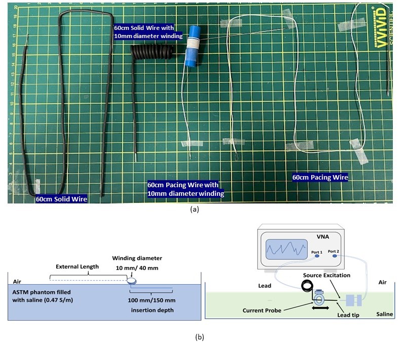
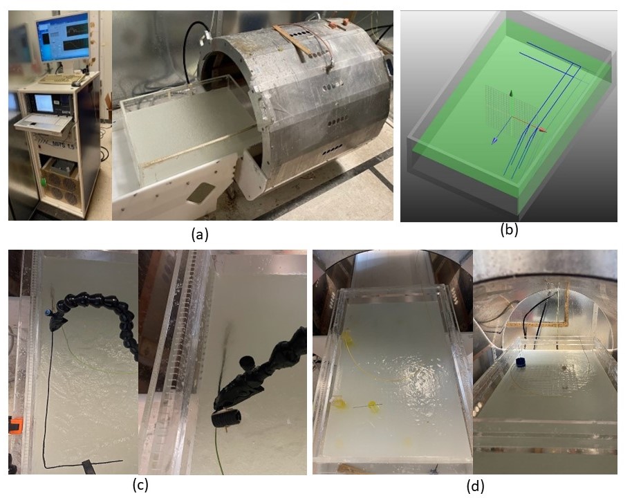
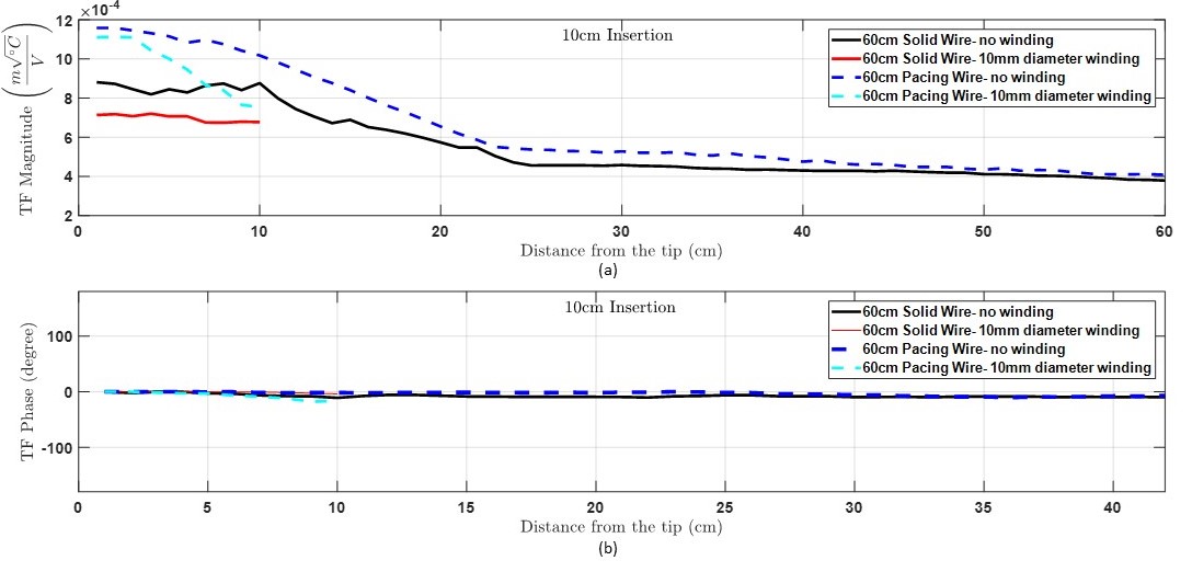
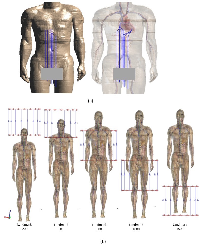
Experiment: A technique of lead trajectory modification is proposed by winding the external portion of the PIPO devices outside the human body. The RF heating is evaluated using the transfer function approach following the methodology described in the ISO TS 10974:2018 [6]. Commercially available temporary cardiac pacing wires and general-purpose insulated solid wires of 60 cm in length were used in this study. During MRI scans, these devices are disconnected from the external pacing devices and terminated as open circuits. Thus, it is possible to make any trajectory modification for the outer portion under MRI. An illustration of the winding of the outer portion and transfer function measurement for modified trajectories is shown in Fig 1. The PIPO devices were placed partially inside the gel (conductivity 0.47 S/m) under a 1.5T RF birdcage coil (MITS 1.5, Zürich MedTech, Switzerland) to measure the RF-induced heating inside the ASTM phantom. Trajectories used for device model scaling and validation are shown in Fig 2. Fiber optical probes were used to record temperatures at the tip of the PIPO devices. The transfer function was measured, scaled, and validated inside the ASTM phantom for 10 mm diameter winding and straight configurations with 10 cm insertions depth, and the scaled TF is shown in Fig 3.Simulation: A Duke model (34yrs, BMI 21.6) [7] was used for the numerical simulations using the full-wave electromagnetic simulation platform SEMCAD X (version 14.8.6.1) based on the Finite Difference Time Domain method. In total, 112 clinically relevant lead trajectories were developed for each device by varying the original 16 trajectories +2 or -2 mm in the x, y, and z-directions, as shown in Fig 4. Then, the RF heating was evaluated for 75 imaging landmarks (-200 mm to 1650 mm; see Fig 4(b)) using three RF transmit body coil sizes in diameter (D) and length (L) in mm (D700, L500; D700, L600; D600, L600) to estimate the effectiveness of our study in mitigating the RF-induced heating.
Results and Discussion
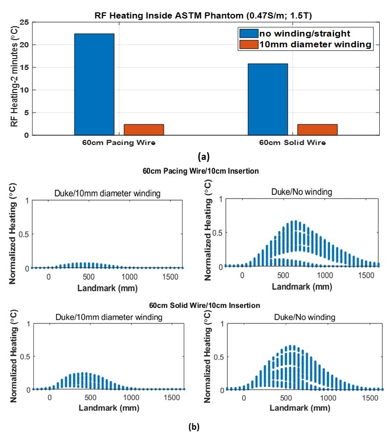
The results of numerical modeling, simulations, and experimental studies are in Figures 3 and 5 below. With the winding of the external portion of PIPO electrodes, we can see up to a 9-fold reduction of the RF heating from the measured results inside the ASTM phantom shown in Fig 5(a). The in-vivo RF heating results from the simulations for the devices with winding and original straight trajectories as a function of imaging landmarks are shown in Fig 5(b). Each landmark contains 672 heating data points, including all clinically relevant trajectories and variations of RF coil sizes. The amount of RF heating mitigation by winding the external portion of the devices resulted in over a 10-fold reduction for the temporary cardiac pacing wire and a 3-fold reduction for the solid wire connected to the ventricles and atrium. The wound portion of the PIPO device behaves as a lumped element rather than a long receiving “antenna” in this condition (i.e., winding diameter:10 mm), so that the induced energy on the entire PIPO system is reduced. Hence, the RF-induced heating contributed by the wound section of PIPO becomes much lower than that from the original straight lead configurations inside the ASTM phantom and human body models.Conclusion
The RF-induced heating for the PIPO devices is evaluated using the transfer function approach. The results show that winding the external portion of a PIPO system can result in up to a 10-fold RF heating reduction compared to the straight configuration of the device lead. Thus, this approach can reduce RF heating significantly, mitigating the risk of tissue damage from RF-induced heating and improving the quality of care for patients with PIPO medical devices under 1.5T MRI. However, the heating profile can be different for different devices and applications. Thus, safety studies and specific protocols are necessary for patients with PIPO medical devices undergoing MRI.Disclaimer
The mention of commercial products, their sources, or their use in connection with material reported herein is not to be construed as either an actual or suggested endorsement of such products by the Department of Health and Human Services.Acknowledgements
No acknowledgement found.References
- J. Liu, J. Zheng, Q. Wang, W. Kainz, and J. Chen, “A Transmission Line Model for the Evaluation of MRI RF-Induced Fields on Active Implantable Medical Devices,” IEEE Trans Microw Theory Tech, vol. 66, no. 9, pp. 4271–4281, Sep. 2018, doi: 10.1109/TMTT.2018.2851975.
- R. Guo, J. Zheng, and J. Chen, “MRI RF-Induced Heating in Heterogeneous Human Body with Implantable Medical Device,” in High-Resolution Neuroimaging - Basic Physical Principles and Clinical Applications, InTech, 2018. doi: 10.5772/intechopen.71384.
- S. Feng, R. Qiang, W. Kainz, and J. Chen, “A technique to evaluate MRI-induced electric fields at the ends of practical implanted lead,” IEEE Trans Microw Theory Tech, vol. 63, no. 1, pp. 305–313, Jan. 2015, doi: 10.1109/TMTT.2014.2376523.
- R. Guo, M. Z. Islam, W. Kainz, and J. Chen, “MRI‐Induced RF Heating Considerations for Devices and Accessories that are Partially in and Partially Out of the Human Body,” in The Application of Heat in Oncology, Wiley, 2023, pp. 533–543. doi: 10.1002/9781119799627.ch32.
- M. Z. Islam, W. Hu, R. Guo, and J. Chen, “Factors Affecting the RF-Induced Heating for the Electrodes Partially Inserted Inside Human Body at 1.5T MRI,” in 2023 IEEE International Symposium on Antennas and Propagation and USNC-URSI Radio Science Meeting (USNC-URSI), IEEE, Jul. 2023, pp. 789–790. doi: 10.1109/USNC-URSI52151.2023.10238180.
- ISO/TS 10974:2018, “Assessment of the safety of magnetic resonance imaging for patients with an active implantable medical device”.
- A. Christ et al., “The Virtual Family - Development of surface-based anatomical models of two adults and two children for dosimetric simulations,” Phys Med Biol, vol. 55, no. 2, 2010, doi: 10.1088/0031-9155/55/2/N01.
Figures