3557
Spinor-EPG: an improved EPG algorithm for fast simulation of the non-ideal slice-profile effect in MRF1Tsinghua University, Beijing, China
Synopsis
Keywords: MR Fingerprinting, MR Fingerprinting, simulation, slice-profile
Motivation: Non-ideal RF slice-profile can affect the accuracy of MRF. However, correcting this effect in dictionary simulation is time-consuming.
Goal(s): To propose an improved simulation algorithm which can correct the RF slice-profile effect in MRF simulation accurately and efficiently.
Approach: We propose an improved MRF simulation method which combines the spinor rotation representation and the extended-phase-graph(EPG) algorithm. The proposed method is validated by retrospective experiments on brain T1 and T2 maps, compared with the EPG algorithm.
Results: The proposed method can correct the non-ideal slice profile effect in MRF dictionary simulation with much faster computational speed.
Impact: We propose an improved simulation algorithm for MRF simulation, which is able to correct non-ideal slice-profile and is as efficient as the EPG algorithm. The proposed method may be helpful for all kinds of MRF imaging applications.
Introduction
Magnetic resonance fingerprinting(MRF)[1] is a quantitative MR imaging technique based on signal simulation and pattern matching. The accuracy of the physical signal model is critical for the quantitative accuracy of MRF. Previous study has shown that the non-ideal slice-profile of the RF pulse can influence the MRF accuracy[2]. Multiple Bloch-simulations can be performed along the slice direction to alleviate this problem[3][4], but this method is time-consuming. At present, most MRF imaging techniques either choose to ignore this issue or reduce the impact of the non-ideal slice-profile by using small flip angles in the MRF pattern.In this work, we propose an improved algorithm for MRF simulation, named "Spinor-EPG", which is inspired by the "Shinnar-Le Roux" algorithm[5]. The proposed method incorporates the spinor rotation representation[6] and the Extended-Phase-Graph(EPG) algorithm[7] into one framework, which is capable to simulate the non-uniform rotation response caused by the RF slice-profile effect. The accuracy and efficiency of the proposed method is validated by retrospective experiments on quantitative brain MRI data.
Method
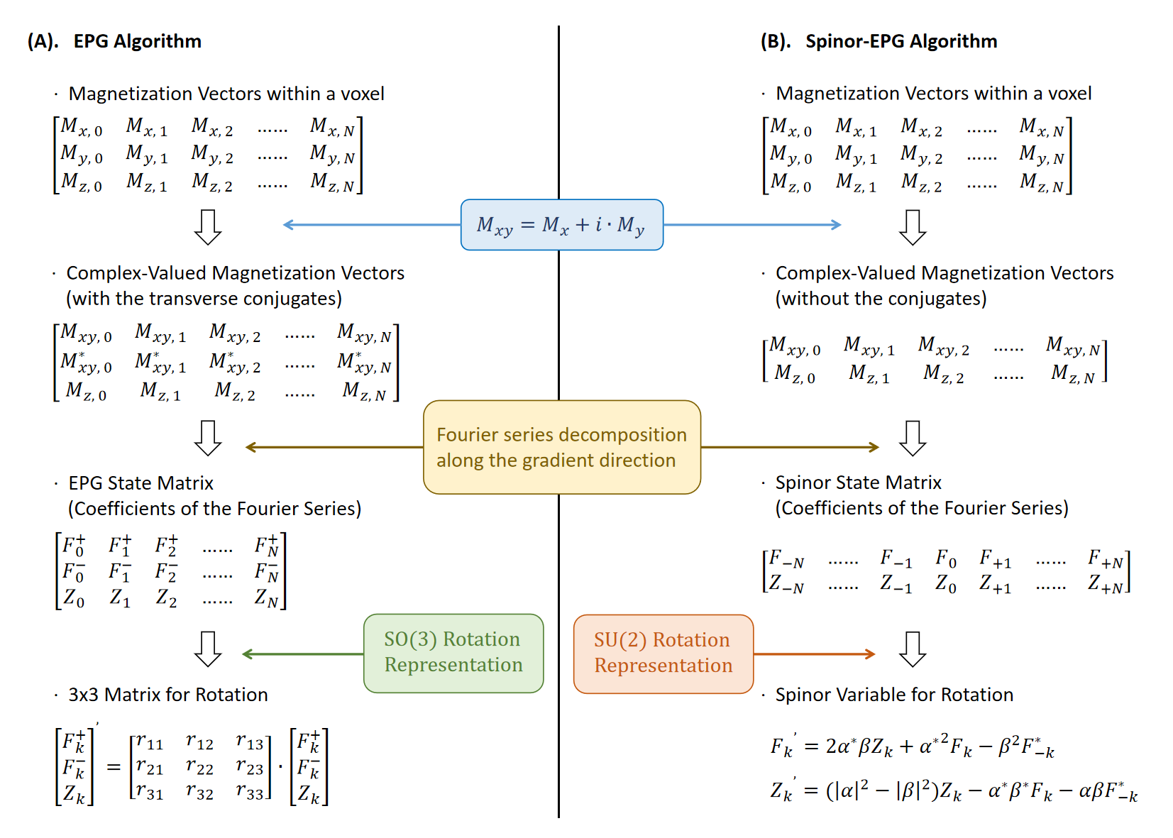
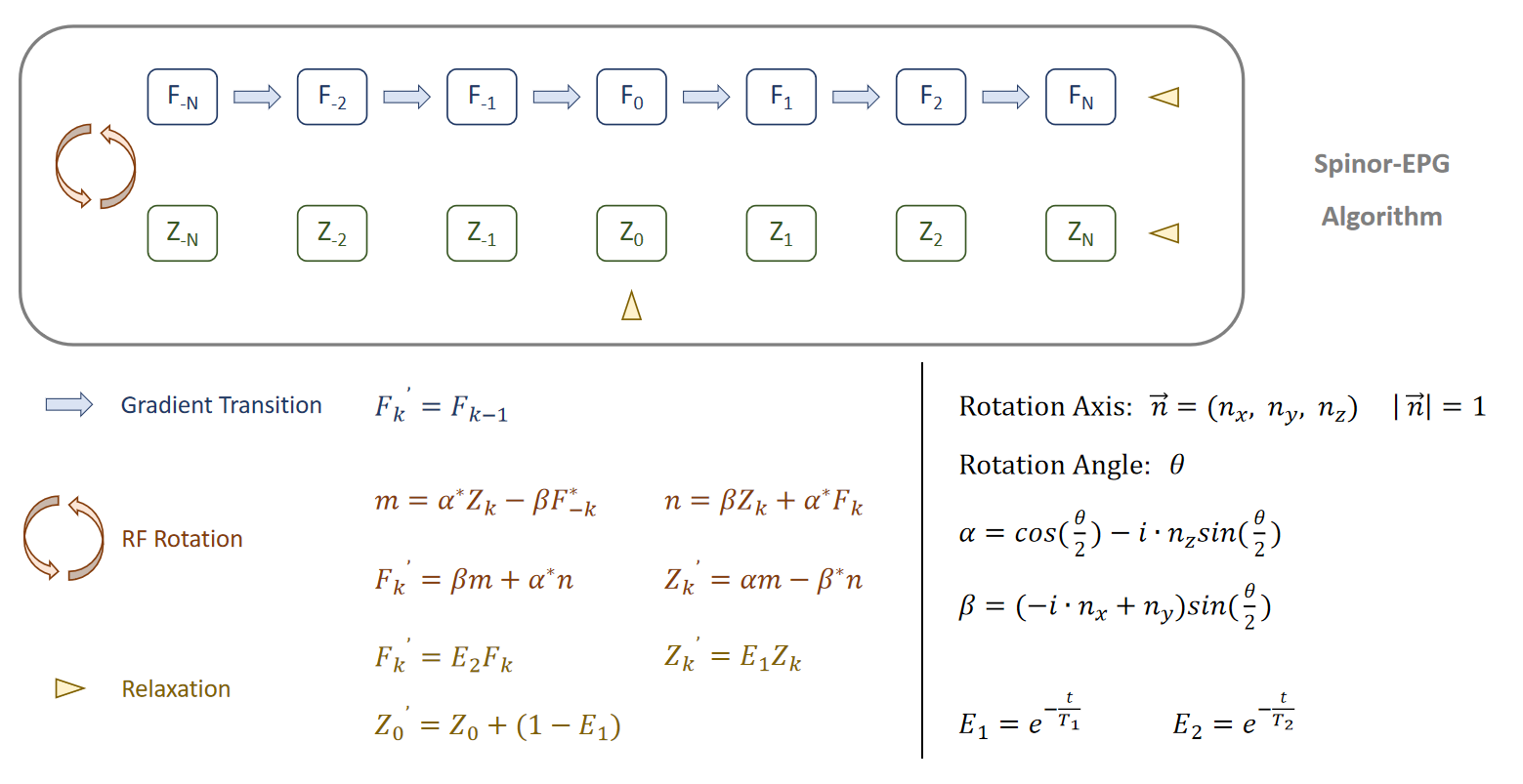
The essence of the proposed Spinor-EPG algorithm is actually rewriting the EPG algorithm with SU(2) rotation representation. As shown in Fig1A, the EPG algorithm uses the complex-valued magnetization vector format, and takes Fourier series decomposition along the gradient direction to obtain the EPG state matrix[8]. The RF pulse is expressed as a 3x3 rotation matrix. However, the 3x3 matrix is a redundant representation for rotation in the 3D space. SU(2) is a more compact rotation format which can represent arbitrary 3D rotation with only two complex numbers $$$\alpha$$$ and $$$\beta$$$ (given $$$\left|\alpha\right|^2+\left|\beta\right|^2=1$$$), which are called spinors[6]. The rotation in 3D space can be rewritten by the following equations:\begin{aligned}Spin\,\,Magnetization&:\,\,\,\,\overrightarrow{M}=\left[\begin{matrix}M_x&M_y&M_z\end{matrix}\right]^T\,\,\,\,\to\,\,\,\,\left\{\begin{matrix}X=M_x+i\cdot M_y\\Z=M_z\end{matrix}\right.\,\,\,\,\,\,\,\,(1)\\\\Rotation\,\,in\,\,3D\,\,space&:\,\,\,\,R_{3\times3}(\overrightarrow{n},\,\theta)\,\,\,\,\to\,\,\,\,\left\{\begin{matrix}\alpha=cos(\frac{\theta}{2})-i\cdot n_z\cdot sin(\frac{\theta}{2})\\\beta=(-i\cdot n_x+n_y)\cdot sin(\frac{\theta}{2})\end{matrix}\right.\,\,\,\,\,\,\,\,(2)\\\\Rotation\,\,Operation&:\,\,\,\,R_{3\times3}(\overrightarrow{n},\,\theta)\cdot\overrightarrow{M}\,\,\,\,\to\,\,\,\,\left\{\begin{matrix}X^{'}=2\alpha^*\beta Z+\alpha^{*^2}X-\beta^2X^*\\Z^{'}=(\left|\alpha\right|^2-\left|\beta\right|^2)Z-\alpha^*\beta^*X-\alpha\beta X^*\end{matrix}\right.\,\,\,\,\,\,\,\,(3)\end{aligned}, where $$$\overrightarrow{n}=(n_x,n_y,n_z)$$$ is the rotation axis which fulfills $$$\left|n\right|^2=1$$$.Note that the SU(2) representation uses the complex-valued magnetization $$$X$$$ and $$$Z$$$. Therefore, we can also consider a group of spin magnetizations within a voxel, and take Fourier series decomposition along the gradient direction(z-direction here) just like in the EPG algorithm:$$\begin{aligned}F_k&=\int_{0}^{1}X(z)\cdot e^{-2\pi ikz}dz\\Z_k&=\int_{0}^{1}Z(z)\cdot e^{-2\pi ikz}dz\end{aligned}\,\,\,\,\,\,\,\,(4)$$Take the Fourier series decomposition along both side of equation(3), and utilize the conjugate property of the Fourier transform $$$F_k(x^*(t))=F_{-k}^*(x(t))$$$, we can get the RF pulse operation in the Spinor-EPG algorithm:$$\left\{\begin{matrix}F_k^{'}=2\alpha^*\beta Z_k+\alpha^{*^2}F_k-\beta^2F_{-k}^*\\Z_k^{'}=(\left|\alpha\right|^2-\left|\beta\right|^2)Z_k-\alpha^*\beta^*F_k-\alpha\beta F_{-k}^*\end{matrix}\right.\,\,\,\,\,\,\,\,(5)$$The gradient-dephasing and relaxation in the Spinor-EPG algorithm are exactly the same as the EPG algorithm. The gradient operation is state-transition between the F states:$$F^{'}_k=F_{k-1}\,\,\,\,\,\,\,\,(6)$$The relaxation operation is decay-multiplication and longitudinal-recovery:$$\left\{\begin{matrix}F_k^{'}=E_2F_k\\Z_k^{'}=E_1Z_k\\Z_0^{'}=Z_0+(1-E_1)\end{matrix}\right.\,\,\,\,\,\,\,\,(7)$$, where $$$E_1=e^{-\frac{t}{T_1}}$$$ and $$$E_2=e^{-\frac{t}{T_2}}$$$. The simulated echo signal can be retrieved from $$$F_0$$$.
The similarity and differences between the EPG and the Spinor-EPG algorithm are shown in Fig1. The details of the Spinor-EPG algorithm are illustrated in Fig2. Note that in Fig2, the equation(5) is further rewritten to have the minimum number of multiplications and additions.
Experiment and Result
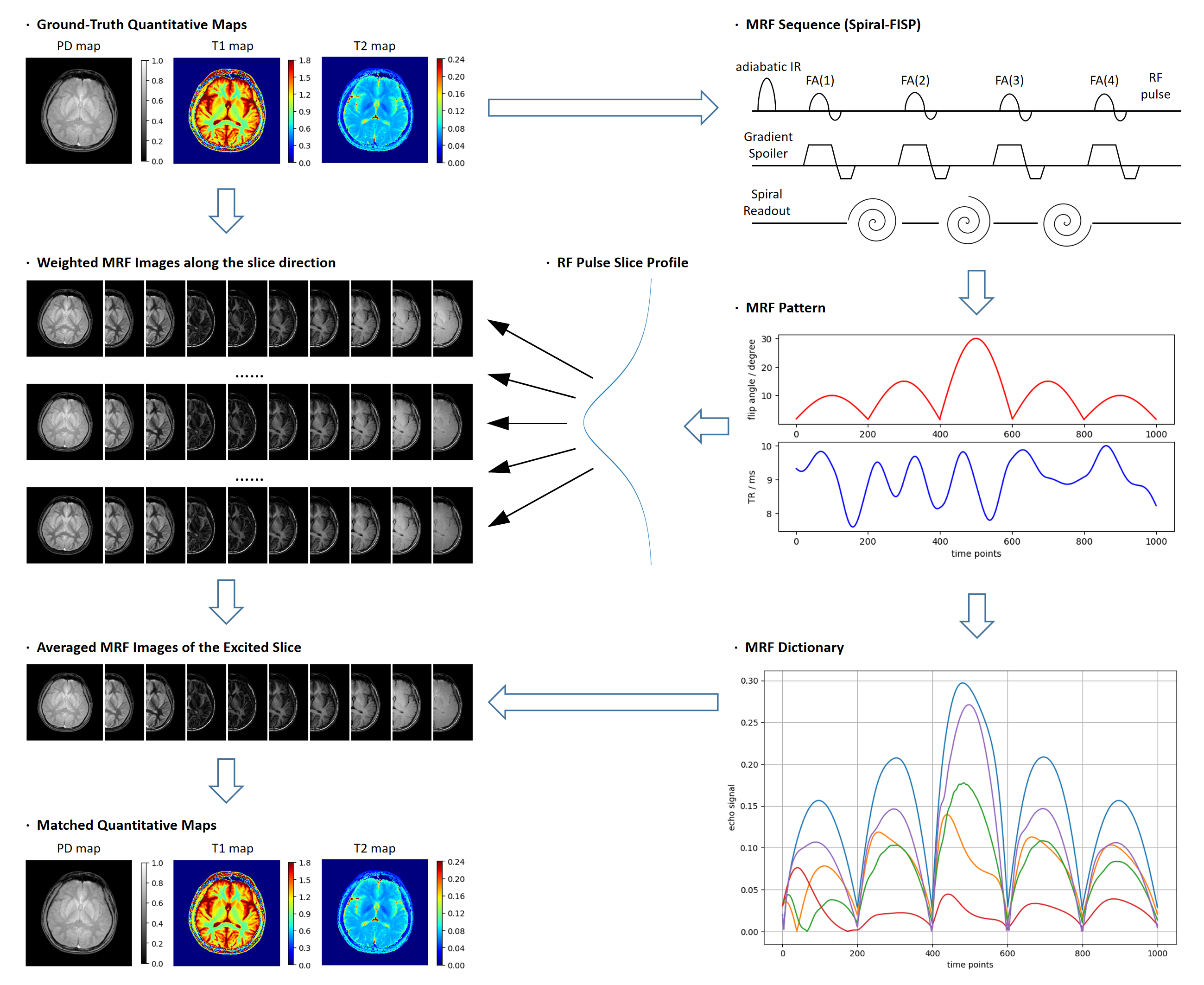
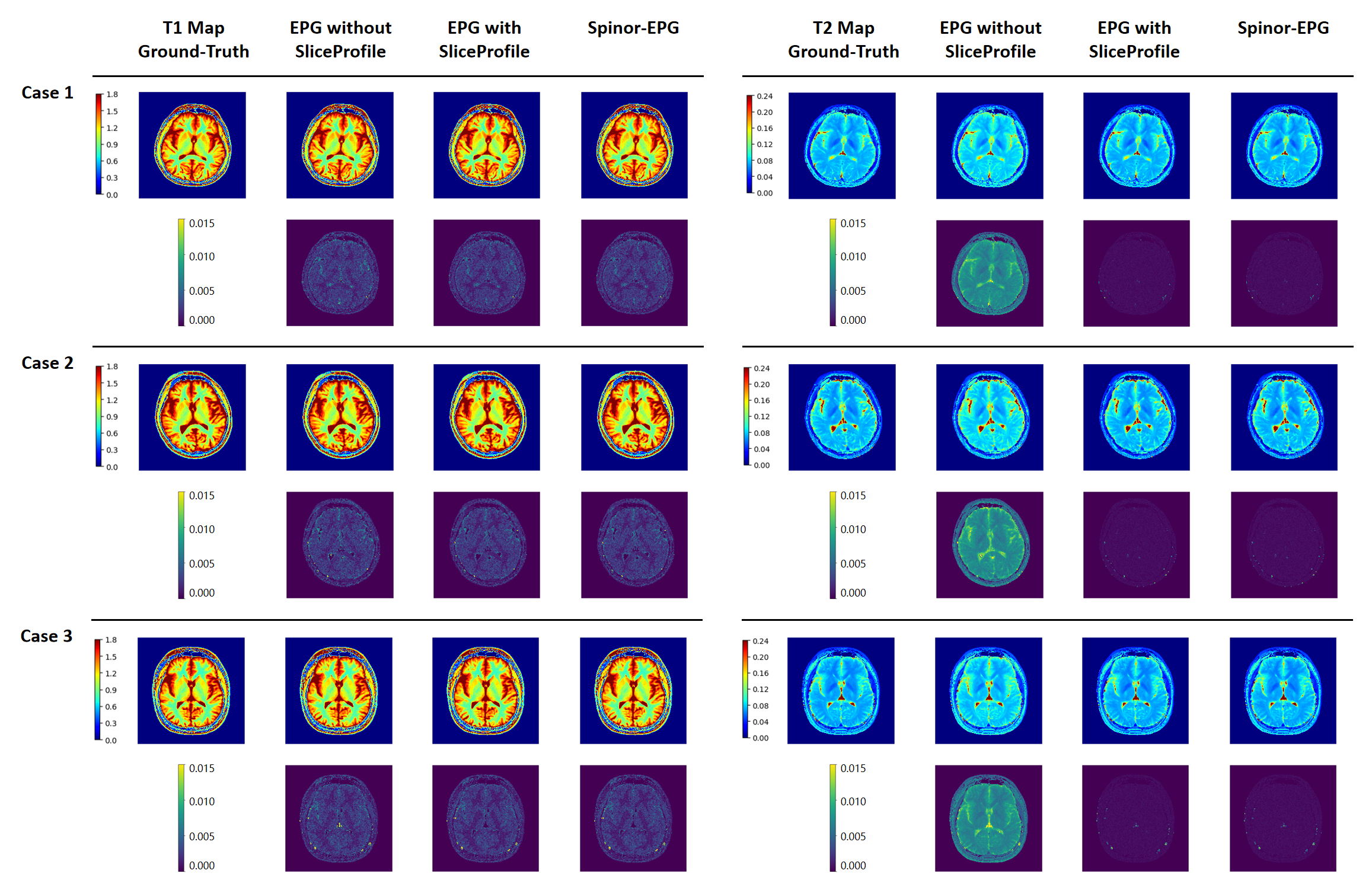
We use the acquired brain T1 and T2 map data to conduct the retrospective experiment, the procedure is illustrated in Fig3. We adopt the widely-used Spiral-FISP MRF sequence[9] in this study. Contrast-weighted MRF images are simulated at different locations, according to the RF pulse slice-profile. The apparent MRF images are calculated by averaging over the locations. Besides, the MRF dictionary is also generated and used for dictionary matching. In order to directly compare the simulation algorithms, we use fully-sampled images for matching in this study to exclude the undersampling effect. Quantification errors are evaluated by comparing with the ground-truth maps. Five data cases are simulated and evaluated in total.The quantification results are displayed in Fig4, where three cases are shown. "EPG without SliceProfile" indicates using EPG for simulation without considering the non-ideal slice-profile. "EPG with SliceProfile" indicates directly using EPG to simulate the non-uniform signals across the slice. "Spinor-EPG" indicates the proposed method. The results demonstrate that the slice-profile effect can cause a significant system bias on the quantification results, especially on the matched T2 maps. The T1 quantification accuracy is relatively robust to the non-uniform excitation within the slice.
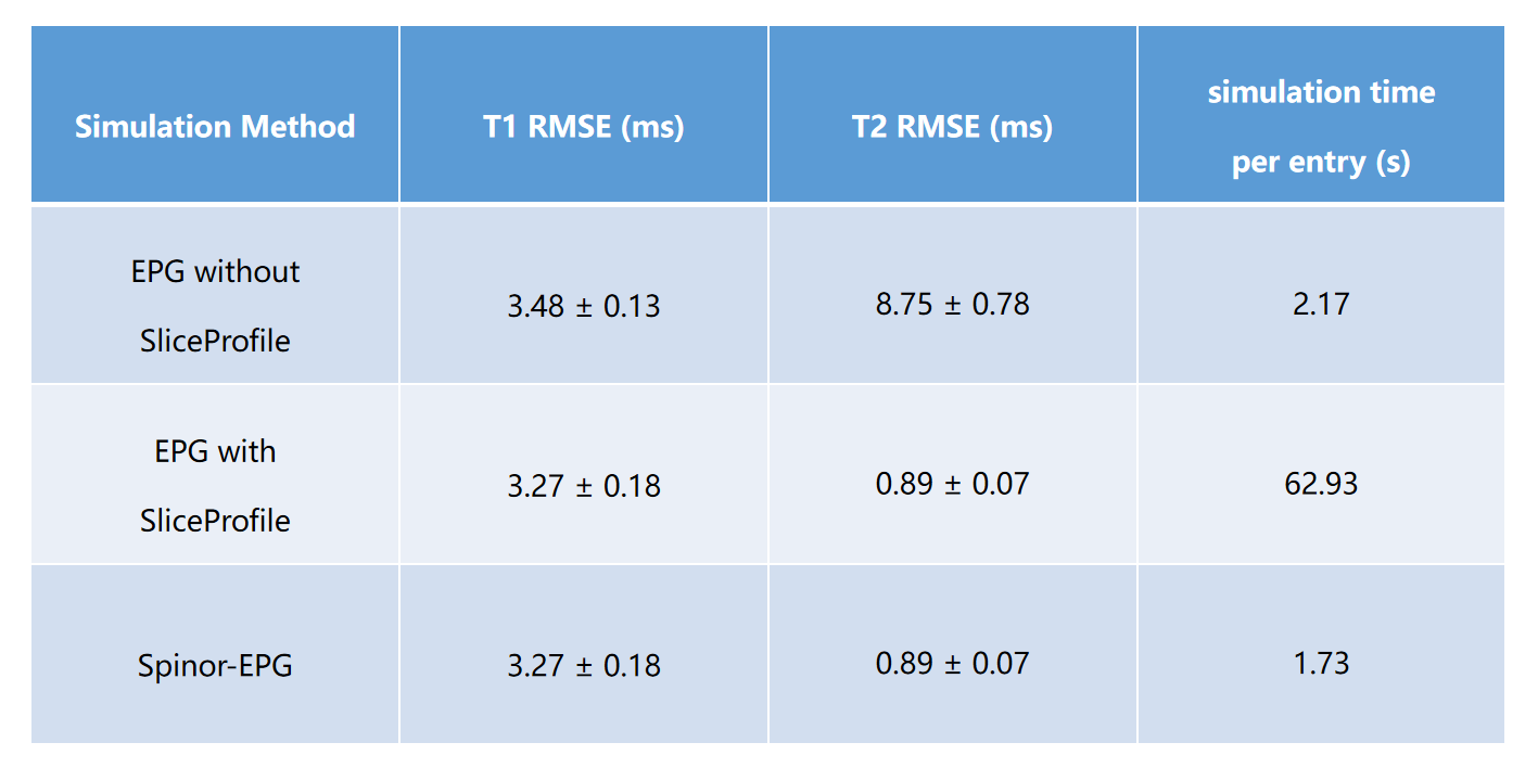
Qunatitative comparisons of different simulation algorithms are summarized in Fig5. Without considering the slice-profile effect, the EPG algorithm will introduce a system bias to the quantification results. Simulate the non-uniform signals directly using the EPG algorithm can correct this system error, at the cost of prolonged simulation time. The proposed Spinor-EPG algorithm can correct this error with even the fastest computational speed, achieving high quanfication accuracy and efficiency simultaneously.
Conclusion
In this work, we propose the Spinor-EPG algorithm to correct the non-ideal slice-profile effect in MRF dictionary simulation. Retrospective experiments demonstrate that the proposed method can improve the quantification accuracy with high computational efficiency.Acknowledgements
No acknowledgement found.References
[1]. Ma, D., Gulani, V., Seiberlich, N., Liu, K., Sunshine, J. L., Duerk, J. L., & Griswold, M. A. (2013). Magnetic resonance fingerprinting. Nature, 495(7440), 187-192.
[2]. Ma, D., Coppo, S., Chen, Y., McGivney, D. F., Jiang, Y., Pahwa, S., ... & Griswold, M. A. (2017). Slice profile and B1 corrections in 2D magnetic resonance fingerprinting. Magnetic resonance in medicine, 78(5), 1781-1789.
[3]. Hamilton, J. I., Jiang, Y., Ma, D., Lo, W. C., Gulani, V., Griswold, M., & Seiberlich, N. (2018). Investigating and reducing the effects of confounding factors for robust T1 and T2 mapping with cardiac MR fingerprinting. Magnetic resonance imaging, 53, 40-51.
[4]. Hong, T., Han, D., Kim, M. O., & Kim, D. H. (2017). RF slice profile effects in magnetic resonance fingerprinting. Magnetic resonance imaging, 41, 73-79.
[5]. Pauly, J., Le Roux, P., Nishimura, D., & Macovski, A. (1991). Parameter relations for the Shinnar-Le Roux selective excitation pulse design algorithm (NMR imaging). IEEE transactions on medical imaging, 10(1), 53-65.
[6]. Le Roux, Patrick. (1995). Introduction to the Shinnar-Le Roux algorithm. 10.13140/RG.2.2.34523.49448.
[7]. Weigel, M. (2015). Extended phase graphs: dephasing, RF pulses, and echoes‐pure and simple. Journal of Magnetic Resonance Imaging, 41(2), 266-295.
[8]. Hargreaves, B. A., & Miller, K. L. (2013). Using extended phase graphs: review and examples. In Proceedings of the 21st Annual Meeting of ISMRM, Salt Lake City, Utah (p. 3718).
[9]. Jiang, Y., Ma, D., Seiberlich, N., Gulani, V., & Griswold, M. A.
(2015). MR fingerprinting using fast imaging with steady state
precession (FISP) with spiral readout. Magnetic resonance in medicine, 74(6), 1621-1631.
Figures