3303
On z-shimming: settings maximizing the signal amplitude may not be derivable from the linear field component and may depend on the echo time1Systems Neuroscience, University Medical Center Hamburg-Eppendorf, Hamburg, Germany
Synopsis
Keywords: fMRI Acquisition, fMRI, z-shim
Motivation: Z-shimming ameliorates through-slice dephasing in T2*-weighted functional neuroimaging but, surprisingly, a linear fit to the field in slice direction may not provide z-shim settings yielding the maximum signal.
Goal(s): To demonstrate that optimum z-shim settings should be obtained from a reference acquisition stepping through a range of z-shims at the desired echo time.
Approach: Numerical simulations of the MR signal were performed for different through-slice field distributions, echo times, and z-shims.
Results: Z-shims derived from the linear fit minimize the dephasing but this is not equivalent to maximizing the signal. Furthermore, optimum z-shim settings may depend on the echo time.
Impact: The results could help to optimize z-shim settings in T2*-weighted acquisitions used for BOLD-based functional neuroimaging by using a reference acquisition stepping through a range of z-shims at the desired echo time rather than a fit to the field distribution.
Introduction
Single, slice-specific z-shim gradient pulses1,2 can ameliorate signal losses caused by through-slice dephasing in T2*-weighted acquisitions for BOLD-based functional neuroimaging without affecting the temporal resolution as has been demonstrated for the human spinal cord3. Because the applied z-shim gradient pulses have a linear field variation, it seems to be reasonable to determine the z-shim settings from the linear component of a measured field distribution in the slice direction4 . However, a recent in vivo study found that this approach may not provide the maximum signal amplitude4 as expected and desired.In order to evaluate and comprehend this finding, numerical simulations of the T2*-weighted signal amplitude were performed for different through-slice field variations, echo times (TEs), and z-shim settings.
Methods
An IDL (Harris Geospatial Solution, Inc.; version 8.8.0) algorithm was implemented to simulate the signal amplitude (ignoring T2 relaxation) for a range of z-shim settings (1001 equidistant values compensating field gradients of up to ±1.0 mT m-1) and TEs (0 ms to 50 ms with a temporal resolution of 0.5 ms) considering different field distributions in the slice direction.For 501 data points across a slice (thickness 5 mm, spatial resolution 10 µm) the phase of the magnetization was calculated. The signal amplitudes across the full slice thickness and sections of it were then obtained by taking the magnitude of the complex sum over the corresponding spatial positions. For each TE, the maximum signal amplitude and the z-shim setting providing it were determined. Furthermore, a linear fit to the field distribution was performed and the nearest z-shim setting determined that has been covered in the simulation.
For simplification, z-shim settings will be considered in gradient units in the following (z-shim gradient moment divided by corresponding TE).
Results
Figure 1 shows simulation results for a linear field variation across the slice: the field distribution (Fig. 1a), the signal amplitude vs. z-shim setting for different TEs(Fig. 1b), and the phase evolution(Fig. 1c) and signal amplitude vs. TE (Fig. 1d) without z-shim and with the z-shim settings (cf. Fig. 1d) determined from the field fit and the signal simulations.Without z-shim, the phase distribution increases linearly with TE (Fig. 1c/left), the corresponding signal amplitude is a sinc centered at TE=0 (lFig. 1d/left): while the signal initially decreases with increasing TE due to increased dephasing and is 0 when the phases are uniformly distributed between ±π, it increases for a range of larger TEs, i.e. despite a further pronounced dephasing, the signal is increased. Thus, reducing/minimizing the phase distribution is not equivalent to enhancing/maximizing the signal.
With z-shimming, the dephasing caused by the linear field variation can be fully compensated for any TE recovering the full signal intensity (Fig. 1c and d/middle and right). The required z-shim setting (i.e. moment divided by TE) yielding the maximum signal amplitude is constant for all TEs (cf. Fig. 1b), the negative of the field gradient, and, thus, can be determined from a linear fit to the field distribution.
However, this can be different for non-linear field variations as demonstrated in Fig. 2 for two constant field sections with a step in-between. Without z-shim, the signal amplitude oscillates with TE and even for certain long TEs the full signal amplitude is obtained (Fig. 2d/left) when the phase difference between the two constant sections is a multiple of 2π (cf. Fig. 2c/left).
Using a z-shim settings based on a field map fit gives a better signal amplitude for small TEs but performs worse for longer TEs (Fig. 2c and d/middle). For short TEs, the z-shim broadens the phase distribution in each section moderately but also reduces the mean phase difference between them yielding a slightly larger signal. But for longer TEs, the broadening increases and decreases the signal of each section considerably yielding a smaller overall signal.
Figure 2b reveals that the optimum z-shim setting changes considerably with TE. For moderate and long TEs,, the signal amplitude obtained with it (Fig. 2c and d/right) is considerably larger than that obtained for the z-shim determined from the fit.
Also for other field variations, z-shim setting from the fit may be non-optimal and the optimum z-shim settings depends on TE as demonstrated in Fig. 3.
Conclusion
For non-linear field variations in the slice direction, the z-shim setting providing the maximum signal amplitude (i) may depend on TE and (ii) cannot be obtained from a fit to the field distribution. Thus, it should be derived from a T2*-weighted reference acquisition stepping through a range of z-shim settings and performed with the TE of the fMRI experimentAcknowledgements
The author is grateful to Falk Eippert and Merve Kaptan for making him aware of the issue and to Toralf Mildner and Johanna Vannesjö for discussion on potential sources for it.References
1. Constable RT. Functional MRI using gradient echo EPI in the presence of large field inhomogeneities.
J Magn Reson Imaging 1995; 5: 746-752.
2. Glover GH. 3D z-shim method for reduction of susceptibility effects in BOLD fMRI.
Magn Reson Med 1999; 42: 290-299.
3. Finsterbusch J, Eippert F, Büchel C. Single, slice-specific z-shim gradient pulses improve T2*-weighted imaging of the spinal cord. Neuroimage 2012; 59: 2307-2315.
4. Kaptan M, Vannesjo SJ, Mildner T, et al. Automated slice-specific z-shimming for functional magnetic resonance imaging of the human spinal cord. Hum Brain Mapp 2022; 43: 5389-5407.
Figures
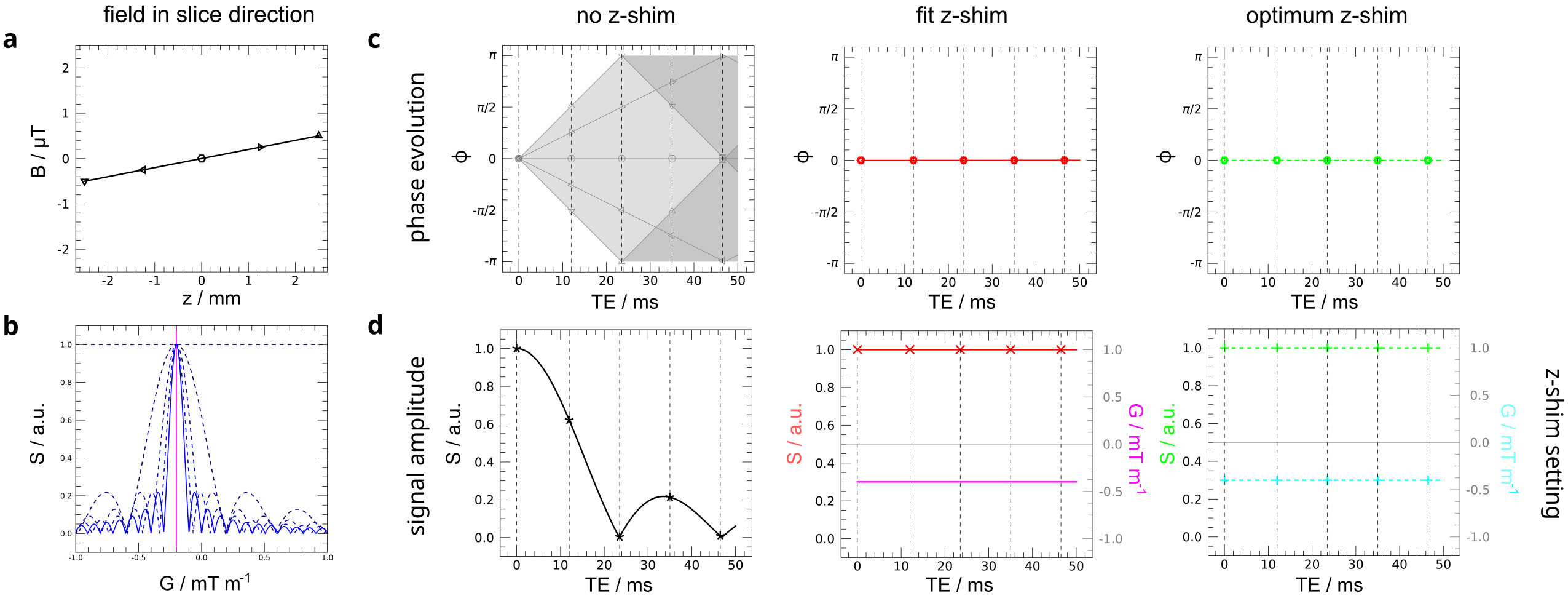
Fig. 1: Results for a (a) linear field variation across the slice thickness: (b) signal amplitude vs. the z-shim setting for different TEs (pink vertical line corresponds to the setting determined from a fit to the field in (a)), (c) phase evolution and (d) signal amplitude (red/green) with corresponding z-shim setting (pink/cyan)) vs. TE without z-shim (left), with z-shim determined from the fit (middle) and optimal z-shim providing the maximum signal (right). In both cases, the signal can be fully recovered and fit and optimum z-shim settings are identical in this example.
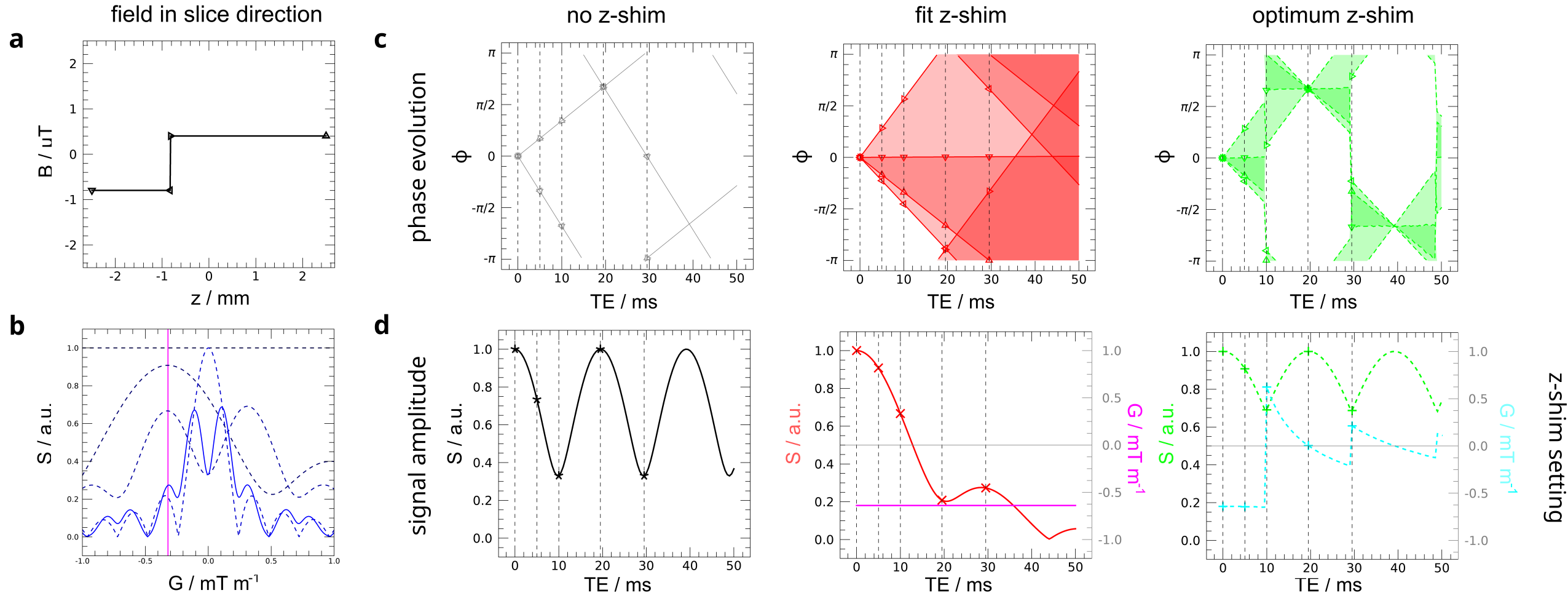
Fig. 2: Plots of the field distribution, signal amplitudes vs. z-shim, and phase evolution and signal amplitude with z-shim setting vs. TE as in Fig. 1 for a field following a step function. The z-shim setting for which the maximum signal amplitude is obtained, depends on TE and is shifted to more positive values for moderate and longer TEs compared to the z-shim setting obtained from the fit (pink). With optimum z-shim settings (cyan), the phase distribution is much narrower in this TE range and the signal amplitude considerably larger.
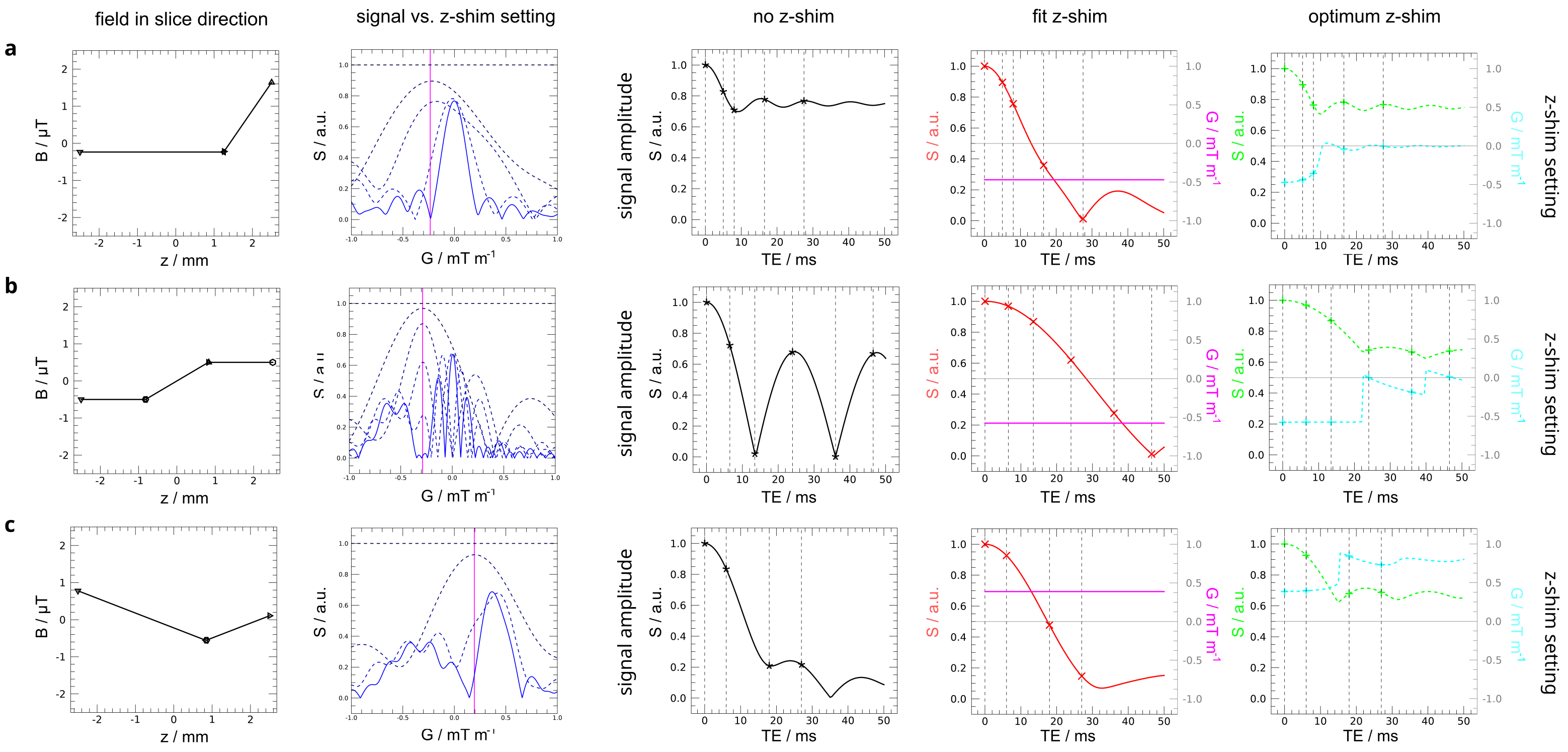
Fig. 3: Plots of the field distribution, signal amplitudes vs. z-shim, and signal amplitude with z-shim setting vs. TE as in Fig. 1 and 2 but for (a) a constant-linear, (b) a constant-linear-constant, and (c) a linear-linear field variation. In all cases, the optimum z-shim setting depends on the echo time and using it can outperform the z-shim setting determined from the fit considerably, in particular for longer TEs.