2848
Characterisation of a new, commercial, partially open-source RF amplifier for low field applications1Leiden University Medical Center, Leiden, Netherlands
Synopsis
Keywords: Low-Field MRI, Low-Field MRI
Motivation: Commercially available open source electronics will help lower the cost and increase accessibility of MRI scanners.
Goal(s): Here we characterise the performance of a commercially available, partially open source RF amplifier designed for low field (<100 mT) MRI
Approach: We examine the gain linearity and frequency stability of the RF amplifier and examine the behaviour of the RF amplifier when transmitting in to a 50 ohm load and RF coil.
Results: The RF amplifier performs well and has sufficient power for low field applications, making it an attractive open source option for low field MRI systems.
Impact: Commercially available open-source electronics will help fundamentally address the cost and access issues hampering the wide step adoption of MRI in low resource settings. In this work we characterise a commercial, partially open-source RF amplifier for low field MRI.
Introduction
There has been renewed interest in low field MRI [1–4] as a way of scaling back both the bulk and cost of MRI systems with the hope that these smaller and potentially cheaper systems will be able to increase accessibility to MRI globally. Unfortunately there has been a lag in the availability in commercial electronics tailor-made for the system characteristics of these modern low field systems.The power requirement for RF coils are substantially lower than at higher field due to much smaller loading effects, leading to very high coil efficiencies in excess of 50uT/√W [5]. RF powers are typically a few tens of Watts, much lower than on conventional MRI systems. As such, RF amplifiers can be made much smaller and lighter, aiding in the goal of increasing mobility of low field MRI scanners.
In this work we characterise a newly developed, partially open-source, small footprint amplifier.
Method
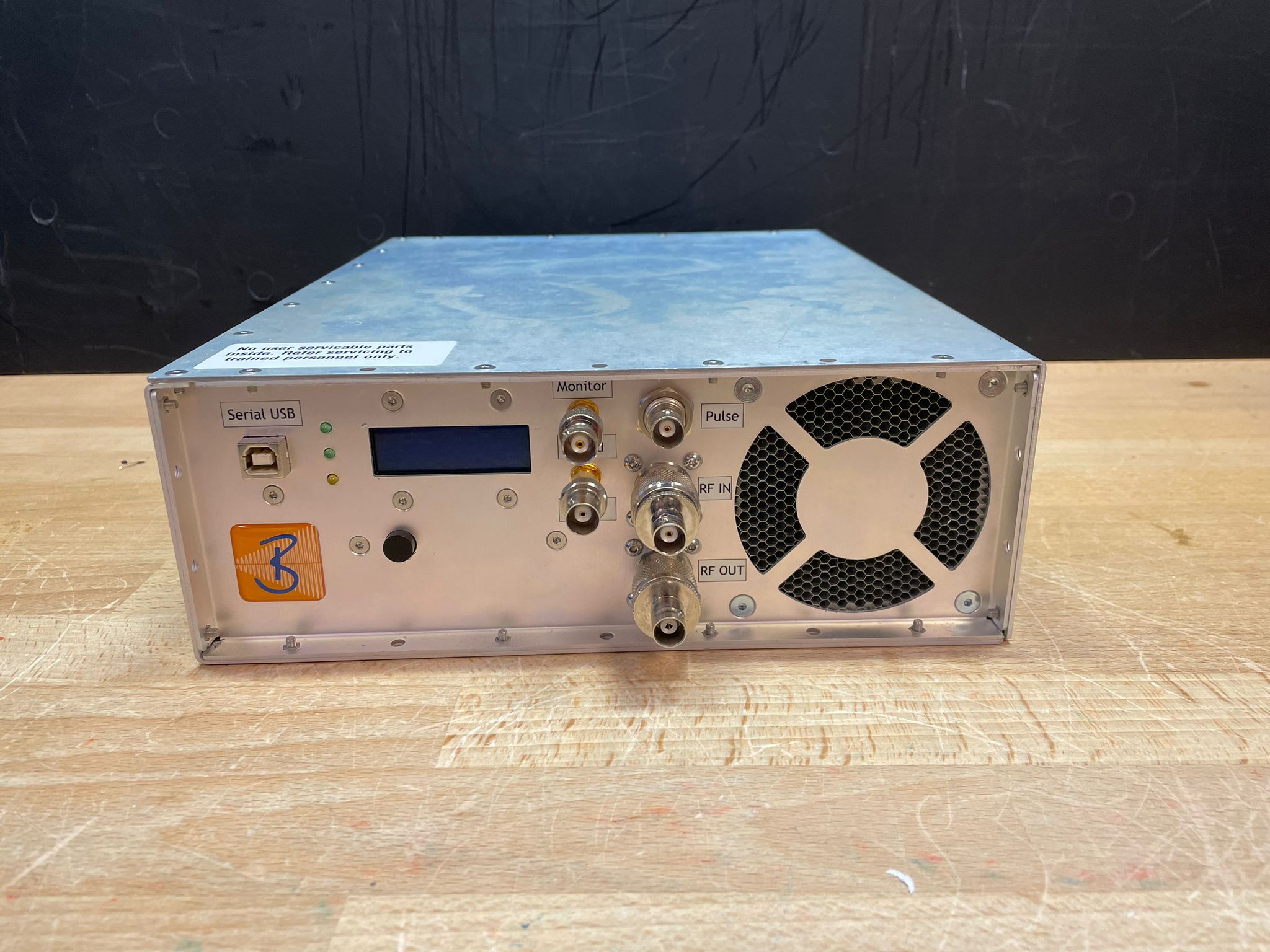
The RF amplifier is a 100 Watt pulsed RF amplifier with a maximum duty cycle of 10%, operating over a frequency range of 1 to 5 MHz developed by Barthel HF-Technik GmBH (Aachen, Germany). Nominal gain is between 50 and 52dB with a gain non-linearity of less than 0.5dB. An enable/error recovery button is provided with optional remote control via USB. Forward and reflected powers can be monitored with connectors on the front. The size of the amplifier is 253x92x391mm3 and weighs 8kg. The internal power and control units will be open sourced, the RF module of the amplifier will remain closed source. Expected retail price of the RF amplifier is around 4000 euros.All tests were performed on a four-channel digital oscilloscope a 100 µs pulse and a deblanking delay of10 µs. The output of the RF amplifier was passed through a 50 dB attenuator to the oscilloscope. For noise characterisation and switching transients the input was terminated with 50 ohms and no attenuator was used. Gain linearity was measured at 2 MHz with an input power range from -50 to 0dBm in 5dB steps. A variable attenuator was placed on the output and varied in equal increments as the input power.
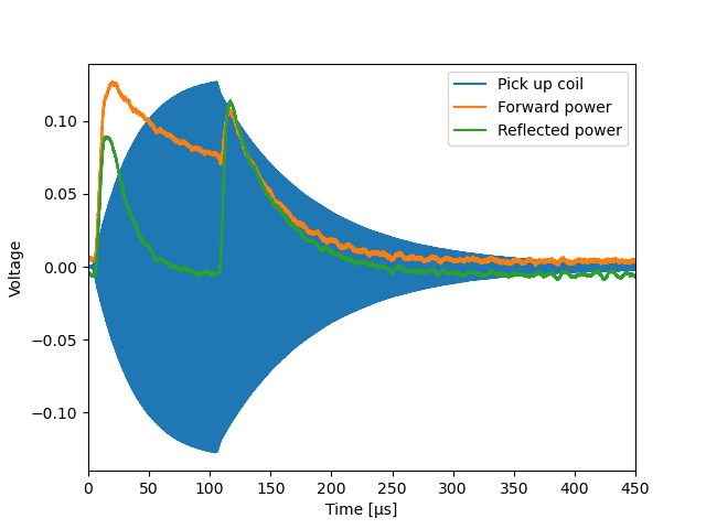
RF pulse shape and the forward and reflected power were measured with a input power of -10dBm. The output was connected directly to a coil tuned to 1.964 MHz with a Q-factor of 320. The signal in the coil was detected using an un-tuned pickup coil.
Results
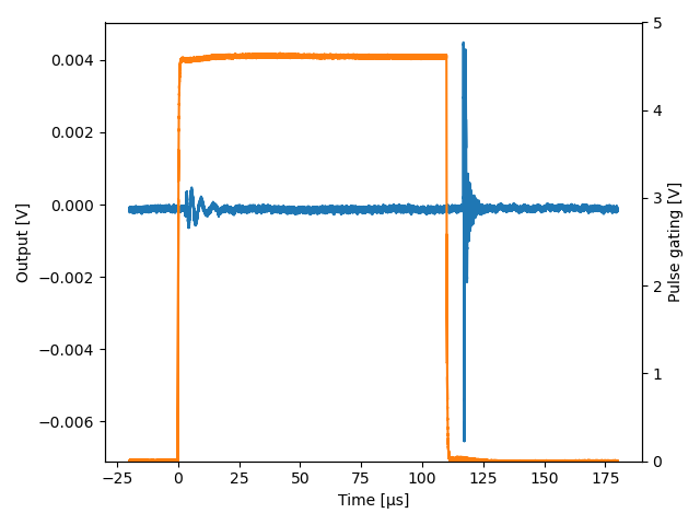
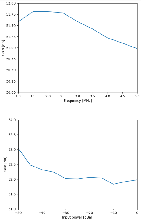
Figure 2 shows the RF amplifier output with a 50 ohm load connected to the input. A small switching transient is visible approximately 3µs after the gating is switched to high and lasts approximately 20µs with a maximum amplitude of 1mVpp. A larger transient is seen around 6µs after the gating is switched to low, lasting around 10 µs with an amplitude of around 12mVpp. Noise levels when the RF amplifier is enabled are indistinguishable from thermal noise on our oscilloscope.The gain of the amplifier showed 0.83dB variance between 1 and 5 MHz. The gain linearity shows larger than expected variation at very low power but this is likely due to relatively high noise vs. RF waveform at the input for low signal voltages. Between -35dBm and 0dBm input power the gain varied 0.26 dB.
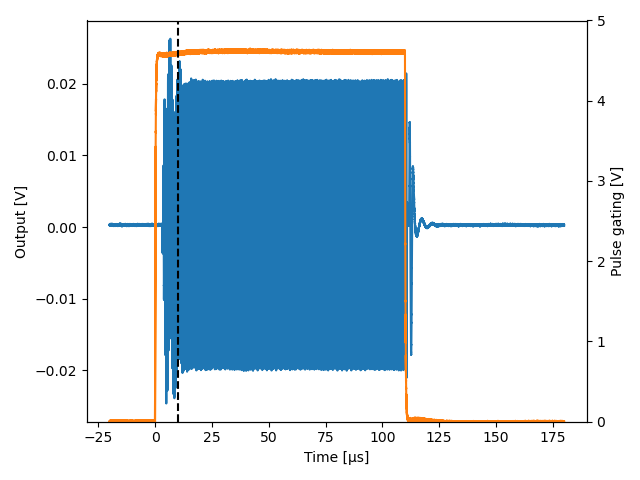
Figure 4 shows the output of the RF amplifier into a 50 ohm load. Similar switching transients as in figure 2 are present and overlap with the start of the RF pulse (marked by the black dashed line) causing a slight distortion to the pulse shape. Figure 5 shows the same RF pulse transmitted into the RF coil. The pulse shape is heavily distorted by the ringing of the high Q RF coil, the ramping and the ring down are visible in the reflected power, and to a lesser extent in the forward power.
Discussion
In this work we characterised the performance of a partially open-source commercial RF amplifier for low field (<100 mT) MRI. The stability of the gain with frequency and input power fall well within acceptable figures and the ripple caused by the enabling of the amplifier doesn’t form a significant problem and will typically be rejected by the T/R switch or the coil itself. Due to the high reflected power caused by the substantially coil ringing in coils with a high Q factor the reflected power monitor can cause the RF amplifier to disable despite not exceeding the maximum duty cycle, this may be managed by changing the integration time of the reflected power monitor.Acknowledgements
This work was funded by a Horizon 2020 ERC Advanced Grant (670629) and the European Partnership on Metrology, co-financed by the European Union’s Horizon Europe Research and Innovation Program (22HLT02 A4IM).References
1. O’Reilly T, Teeuwisse WM, Webb AG. Three-dimensional MRI in a homogenous 27 cm diameter bore Halbach array magnet. J Magn Reson. 2019;307:106578. doi:10.1016/j.jmr.2019.106578
2. Cooley CZ, McDaniel PC, Stockmann JP, et al. A portable scanner for magnetic resonance imaging of the brain. Nature Biomedical Engineering. 2021;5(3):229-239. doi:10.1038/s41551-020-00641-5
3. Liu Y, Leong ATL, Zhao Y, et al. A low-cost and shielding-free ultra-low-field brain MRI scanner. Nat Commun. 2021;12(1):7238. doi:10.1038/s41467-021-27317-1
4. He Y, He W, Tan L, et al. Use of 2.1 MHz MRI scanner for brain imaging and its preliminary results in stroke. Journal of Magnetic Resonance. 2020;319:106829. doi:10.1016/j.jmr.2020.106829
5. Webb A, O’Reilly T. Tackling SNR at low-field: a review of hardware approaches for point-of-care systems. Magn Reson Mater Phy. 2023;36(3):375-393. doi:10.1007/s10334-023-01100-3
Figures