2836
Self Shielding Multi-turn RF Surface Coil Planar Arrays for Low-field MRI at 2MHz1Physics, Case Western Reserve University, Cleveland, OH, United States, 2Biomedical Engineering, Case Western Reserve University, Cleveland, OH, United States, 3Radiology, Case Western Reserve University, Cleveland, OH, United States
Synopsis
Keywords: Low-Field MRI, RF Arrays & Systems
Motivation: Low field MRI using RF based gradients can reduce both its cost and bulk. Multi-channel RF arrays can enable this. Effective methods to decouple these coils and mitigate EMI are necessary for building efficient RF encoding based systems.
Goal(s): To improve multi-channel RF array performance for low field MRI and automatically reject EMI.
Approach: Develop an array of multi-turn surface coils with concentric shields. These are verified with an EMI rejection test and geometric decoupling tests.
Results: These coils automatically reject environmental noise and add two additional geometric coupling modes when used in an array, allowing for more array configurations.
Impact: RF array decoupling and EMI mitigation are challenging at low-field. We develop a method to decouple RF coil arrays by leveraging counter-wound multiturn surface coils allowing for additional decoupling modes. These coils are also self-shielded, providing added EMI mitigation.
Introduction
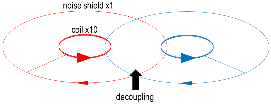
RF coil arrays provide several advantages for speed and SNR gain. Low field MRI may benefit from RF coil arrays, but large arrays have not been achieved yet in part due to the lack of decoupling strategies that are suitable for low-field. We propose a method for coil decoupling that leverages the use of counter-wound concentric multi-loop coils that create multiple geometric decoupling methods. In a given multi-turn surface coil, one coil having fewer turns and a larger radius is similarly sensitive to a large homogeneous field, but less sensitive to the imaging volume. When these counter-wound loops with different radii are joined in series and placed coaxially, much of the EMI received by the imaging coil is canceled by the EMI received by the shielding (counter-wound) coil, and the coil field magnitude the imaging volume is minimally impacted (fig2).This shield coil in turn introduces new geometric decoupling modes for maintaining channel independence in an array. Methods have been described in the past for decoupling at higher field1 and EMI rejection with a single channel,2 but these also used a 2:1 imaging and shield coil ratio, which is more detrimental to coil field strength in the imaging volume. This coil design is particularly useful at frequencies below 10 MHz, since adding turns that increase coil inductance leads to higher B1+ efficiency and allows for better shield ratios.
Methods
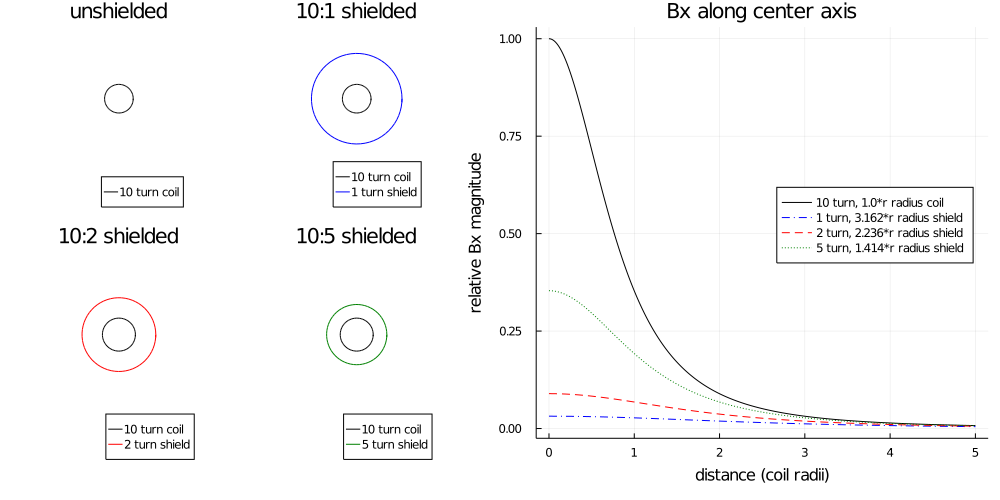
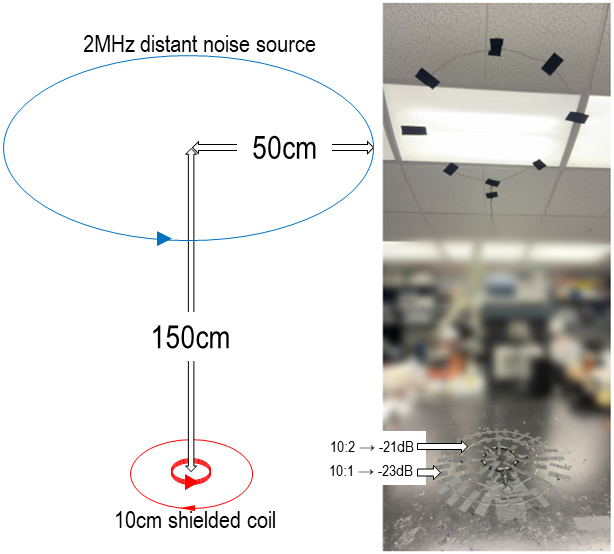
Theory: For a given multiturn surface coil with ns turns and radius (rs), a counter loop with ns<nc turns to remove EMI will have a radius: $$rc=sqrt(nc/ns)*rs.$$This gives a counter loop with approximately the same total sensitivity to a homogenous field, which when reversed cancels EMI. If rc and rs are close, coil field strength is reduced in the imaging volume due to the close proximity of the shield (Fig2). This is remedied by increasing nc with rc>rs.EMI mitigation : A coil with rs = 4.55 cm with ns = 10 turns is used as the imaging loop. Two configurations are tested for the counter loops: 1) nc = 1 and rc = 15.81cm from Eq 1 for a 10:1 self shielded coil. 2) nc = 2 and rc = 11.18cm from Eq 1 for a 10:2 self shielded coil. Both of these configurations are tuned to 2MHz and matched. Both of these configurations were tested for EMI mitigation by transmitting 2MHz from a 50 cm radius coil at a distance of 150cm from the test setup.
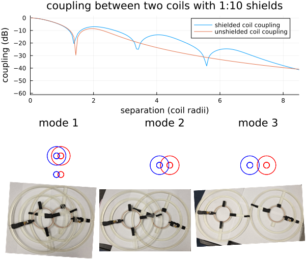
Coil decoupling: Simulations were performed to test for decoupling using two 10:1 self shielded coils by varying the distance between their centers. Three geometric decoupling modes are predicted (fig4). This includes the decoupling mode of unshielded surface coils. The new modes are shields overlapping each other, and shields overlapping each other and the coils. This is further validated experimentally by creating 3D printed formers and winding both coils. These are tuned to 2MHz for testing. An S21 measurement into a pair of decoupled pickup-loops coupled through one shielded coil showed when the other coil was fully decoupled by independence of the first coil’s tune.
Results
Noise rejection testing showed good performance with the 10:2 shielded coil and improved performance with the 10:1 shielded coil, 21dB and 23dB reductions in noise magnitude respectively relative to the unshielded 10 turn 10 cm coil.For 10:1 coils we verified the decoupling modes, positions where the coil tunes were independent are pictured in fig4.
Discussion
The tradeoff between loss of coil field in the imaging volume and shielded coil size is an important consideration, likely to depend on the specific application. In scenarios where EMI noise dominates, losing coil field strength may be worth it, otherwise it may adversely impact SNR. Having a primary coil with as many turns as possible is key to limiting the impact of the shield on imaging performance.The important feature of these shielded coils is performance in an array. While arrays are not often necessary at low field, for methods such as SENF they are essential.1 Adding these methods for decoupling will likely ease array construction.
For EMI mitigation, the best case shield is a single turn. For a 10 turn coil, this radius is large, so we also compare performance to a more compact 10:2 shielded coil and show shielding is mildly reduced.
Conclusion
For low field imaging methods which rely on RF gradients for spatial information such as SENF, adding concentric shields to multi-turn surface coil arrays is likely beneficial. This not only cancels some environmental noise automatically, but adds additional geometric decoupling modes.Acknowledgements
No acknowledgement found.References
1 Lanz, T., and M. Griswold. "Concentrically shielded surface coils-a new method for decoupling phased array elements." Proc Intl Soc Mag Reson Med. Vol. 14. 2006.
2 Johns, Michael L, Fridjonsson, Einar O, Vogt, Sarah J & Haber, Agnes. “Mobile NMR and MRI: Developments and Applications”. 978-1-84973-915-3 (2016)
3 Christopher Elliot Vaughn, N Reid Bolding, Mark A Griswold, and William A Grissom. “Selective Encoding through Nutation and Fingerprinting (SENF) using Quadratic RF Phase Modulation and the Bloch-Siegert Shift” Proceedings of the 32nd Annual Meeting of ISMRM, Toronto, ON, 2023. Abstract 1101.
Figures