2835
A LOW-COST AND OPEN-SOURCE MAGNET TEST STATION TO IMPROVE THE ASSEMBLY PROCESS OF LOW-FIELD SCANNER MAGNETS1Istituto Nazionale di Ricerca Metrologica (INRiM), Torino, Italy, 2Physikalisch-Technische Bundesanstalt (PTB), Berlin, Germany
Synopsis
Keywords: Low-Field MRI, Low-Field MRI, Permanent Magnets
Motivation: The building process of low-field scanners magnets, when composed of a large number of small permanent magnets, is time-consuming and error-prone due to the highly repetitive task.
Goal(s): To design a low-cost and open-source solution making the magnet building process faster and more reliable.
Approach: To use a Hall sensor to distinguish between working and defective permanent magnets. Furthermore, to take advantage of the attractive force between two permanent magnets to identify the polarization direction.
Results: A magnetic test station is designed. CAD drawings and scripts are made available on the GitHub repository.
Impact: A magnet test station allowing for an easy and straightforward testing of small permanent magnets is proposed. The test station makes the construction process of low-field scanner magnets, composed of a large number of permanent magnets, faster and more reliable.
Introduction
One common strategy to design low-field MRI scanners is to generate the B0 static field by means of permanent magnets (PMs). The use of a large number of small PMs offers the significant advantage of decreasing the magnet enclosure weight and increasing safety during the assembly process.1-5 However, this comes at the cost of a time consuming construction process, where each magnet has to be singularly positioned in dedicated slots on a designed frame.1,2 Furthermore, most of the time the polarization of the magnets is not marked by the manufacturer and for large batches it is likely to come across defective samples that have to be excluded to avoid compromising the eventual magnet performance.In this abstract we propose a station for testing the PMs. The magnet test station (MTS) allows for testing each magnet in a simple and straightforward way, reducing the chance of errors due to the performance of a repetitive task and significantly accelerating the magnet building procedure.
Methods
The MTS complies with the following requirements:1. To provide an easy and straightforward way to identify the polarization of each PM;2. To identify defective PMs;
3. To keep trace of the results;
4. To be low-cost, easy-to-reproduce and open-source.
To accomplish the first requirement we take advantage of the attractive magnetic force applied by a reference magnet (RM) on the magnet under test (MUT). Once the polarization of the RM is known, the attractive force defines the polarization of the MUT.
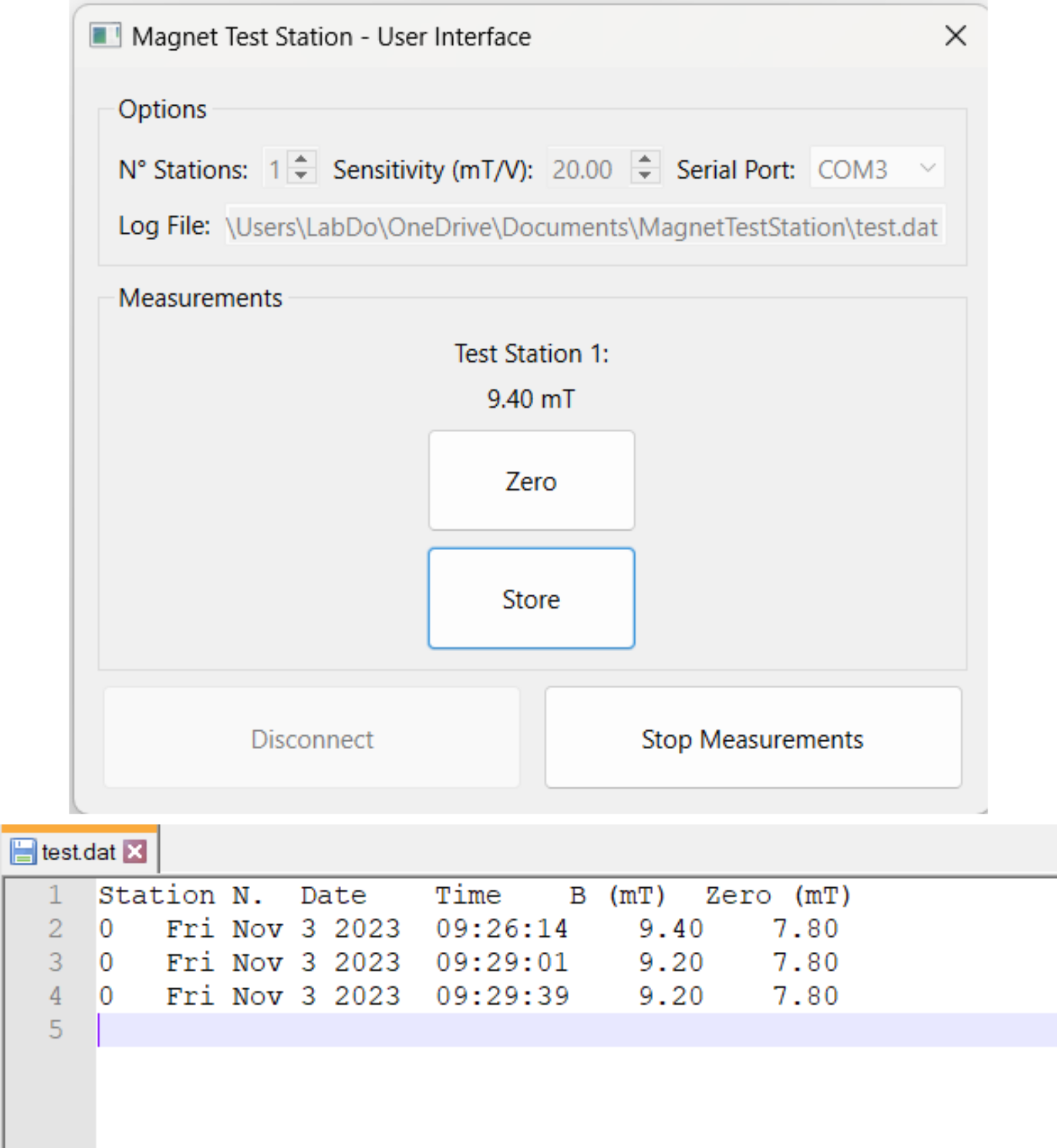
The second requirements is satisfied by a Hall effect sensor placed at the midpoint between the RM and the MUT to measure the resultant magnetic field amplitude B(0). A defective magnet corresponds to a lower magnetic field amplitude and can be safely excluded. The signal from the Hall sensor (A1324LUA-T) is measured by means of an Arduino board interfaced to the PC through a serial communication protocol. A User Interface is therefore designed in Python to print the measured values and to store them in a log file.
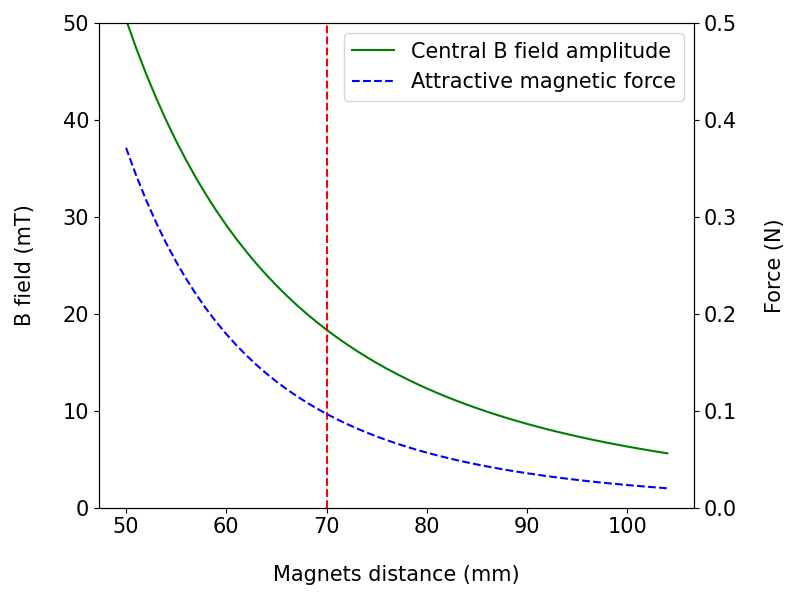
The reciprocal distance d between the RM and the MUT should be short enough to result in a sufficient attractive force but not excessively short to saturate the dynamic range of the Hall sensor. In this regard, the following represent the design equations:
$$B(0)=\frac{\mu_0}{2\pi}\frac{m_1+m_2}{(d/2)^3}$$
$$F=\frac{3\mu_0}{(2\pi)} \frac{m_1m_2}{d^4}$$
where the dipole approximation is applied, $$$m_1$$$ and $$$m_2$$$ are the magnetic moments of the RM and MUT.
Results
The MTS is optimized to test NdFeB (N52) 12x12x12 mm3 cubic PMs. For the sake of practicality, the same kind of PM is used as RM.Figure 1 shows the attractive magnetic force and the magnetic field amplitude at the central point between the RM and MUT as a function of their distance. For a 70 mm distance, the expected magnetic field amplitude in the center is about 18 mT and the attractive force is about 0.1 N.
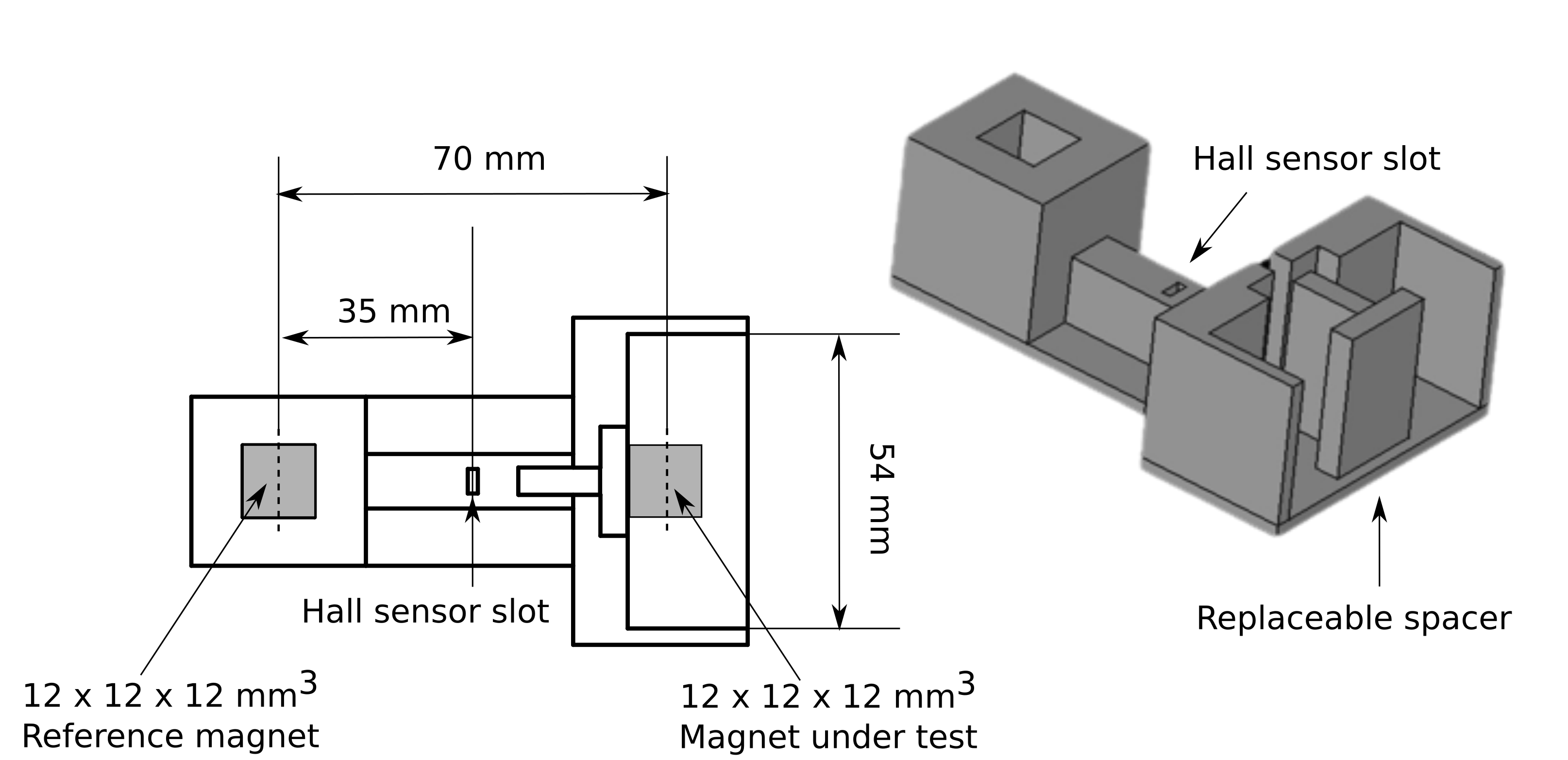
Figure 2 shows the sketch of the realized MTS frame considering a 70 mm distance between the RM and MUT.
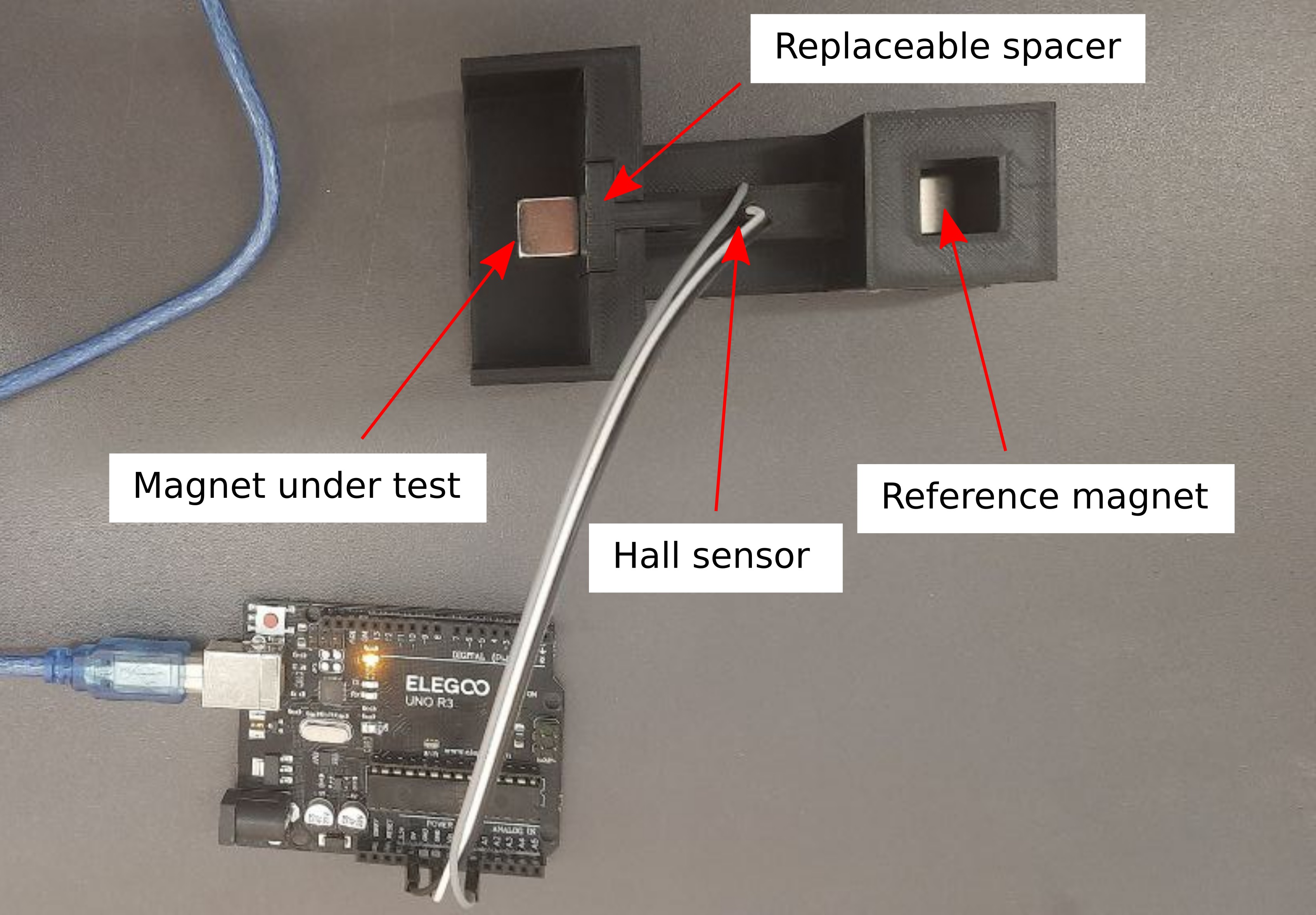
Figure 3 represents the 3D printed MTS frame with the RM and MUT in place and the Hall sensor connected to the Arduino board.
Finally, Figure 4 represents a screenshot of the Python User Interface together with an example of a log generated file.
Discussion
For NdFeB 12x12x12 mm3 cubic PMs a 70 mm distance between the RM and MUT leads to a magnetic field amplitude measured by the A1324LUA-T Hall sensor lower than its saturation value (50 mT) and to an attractive force (see Figure 1). In case different PMs have to be tested, it is possible to replace the spacer (see Figures 2 and 3) without having to print another frame.The user interface allows to use up to four contemporary MTSs whose measured magnetic field values can be logged in the same file. Besides the MTS number, each entry of the log file also reports information about date and time of the acquisition, the measured value and the zero set (see Figure 4).
Using the 10 bit ADC converter of the ATmega328 microcontroller, it is possible to obtain a magnetic field resolution about 0.1 mT. Whereas this should be enough to distinguish between working and defective magnets, the resolution can be improved by using external ADC converters.
Conclusion
The parametrized CAD drawings, User Interface and Arduino codes relevant to the MTS are available on GitHub5. The MTS demonstrate to be a low-cost but effective solution to improve the building workflow of low-field scanners using a large number of small PMs.Acknowledgements
The project (23HLT02 A4IM) has received funding from the European Partnership on Metrology, co-financed from the European Union’s Horizon Europe Research and Innovation Programme and by the Participating States.
References
- O’Reilly T, Teeuwisse W. M., and Webb A. G. Three-dimensional MRI in a homogenous 27 cm diameter bore Halbach array magnet. Journal of Magnetic Resonance. 2019; 307
O’Reilly T, Teeuwisse W. M., Gans D., Koolstra K., and Webb A. G. In vivo 3D brain and extremity MRI at 50 mT using a permanent magnet Halbach array. Magn. Reson. Med., 2021; 85(1):495–505.
Cooley C. Z, Hskell M. W., Cauley S. F. et al. Design of sparse Halbach magnet arrays for portable MRI using a genetic algorithm. IEEE Trans Magn. 2018; 54(1).
Cooley, C. Z., Stockmann, J. P., Armstrong, B. D., et al. Two-dimensional imaging in a lightweight portable MRI scanner without gradient coils. Magn. Reson. Med. 2015; 73(2): 872-883.
McDaniel P. C., Cooley C. Z., Stockmann J.P., Wald L.L. The MR Cap: A single-sided MRI system designed for potential point-of-care limited field-of-view brain imaging. Magn Reson Med. 2019; 82(5):1946–1960.
Zanovello U. MagnetTestStation. github.com/umbertozanovello/MagnetTestStation. Accessed November 6, 2023
Figures