2730
Characterization of deformable tumor models for real-time adaptive radiotherapy plan evaluation1Department of Medical Biophysics, University of Toronto, Toronto, ON, Canada, 2Department of Radiation Oncology, Sunnybrook Health Sciences Centre, Toronto, ON, Canada, 3Department of Physics, Toronto Metropolitan University, Toronto, ON, Canada, 4Department of Radiation Oncology and Molecular Radiation Sciences, Johns Hopkins Medicine, Baltimore, MD, United States, 5Physical Sciences Platform, Sunnybrook Research Institute, Toronto, ON, Canada
Synopsis
Keywords: Phantoms, Phantoms, Real-time, adaptive radiotherapy
Motivation: Real-time adaptive radiotherapy, which involves tracking a target during internal patient motion, may soon reach clinical implementation. Quality assurance methods will be needed, especially for deformable motion.
Goal(s): Develop a method of characterizing the relationship between input and target shape for deformable tumor model phantoms.
Approach: We acquired dynamic MRI and static CT of a deformable phantom subject to several input waveforms. We approximated the target as an ellipsoid and created a linear model to predict the ellipsoid parameters from the input.
Results: The ellipsoid parameters of the target subject to a new waveform could be predicted to within a millimeter.
Impact: We demonstrated a simple method to determine the relationship between input and target geometry for deformable tumor model phantoms. Patient-specific tumor motion can be recreated by inverting the input-target geometry relationship for quality assurance of real-time adaptive radiotherapy plans.
Introduction
MRI-linear accelerators (MR-Linacs) are combined MRI and radiotherapy devices that could enable real-time MR-guided target tracking in the future.1–3 Robust quality assurance methods are required, especially when the tumor shape deforms during internal motion.4 Commercial phantoms with deformable tumor models are available, allowing recreation of patient motion via MRI-compatible motors.5,6 However, the relationship between the input (requested position) and the tumor deformation state is not always characterized. The objective of this study was to develop a method for determining this input-target geometry relationship, which will enable recreation of measured in vivo motion for quality assurance. Our method involves acquiring dynamic MRI while the phantom is in motion, approximating the target geometry by a simple 3D shape (e.g., an ellipsoid), then fitting a low-order polynomial (e.g., a line) to the shape’s parameters.Materials and Methods
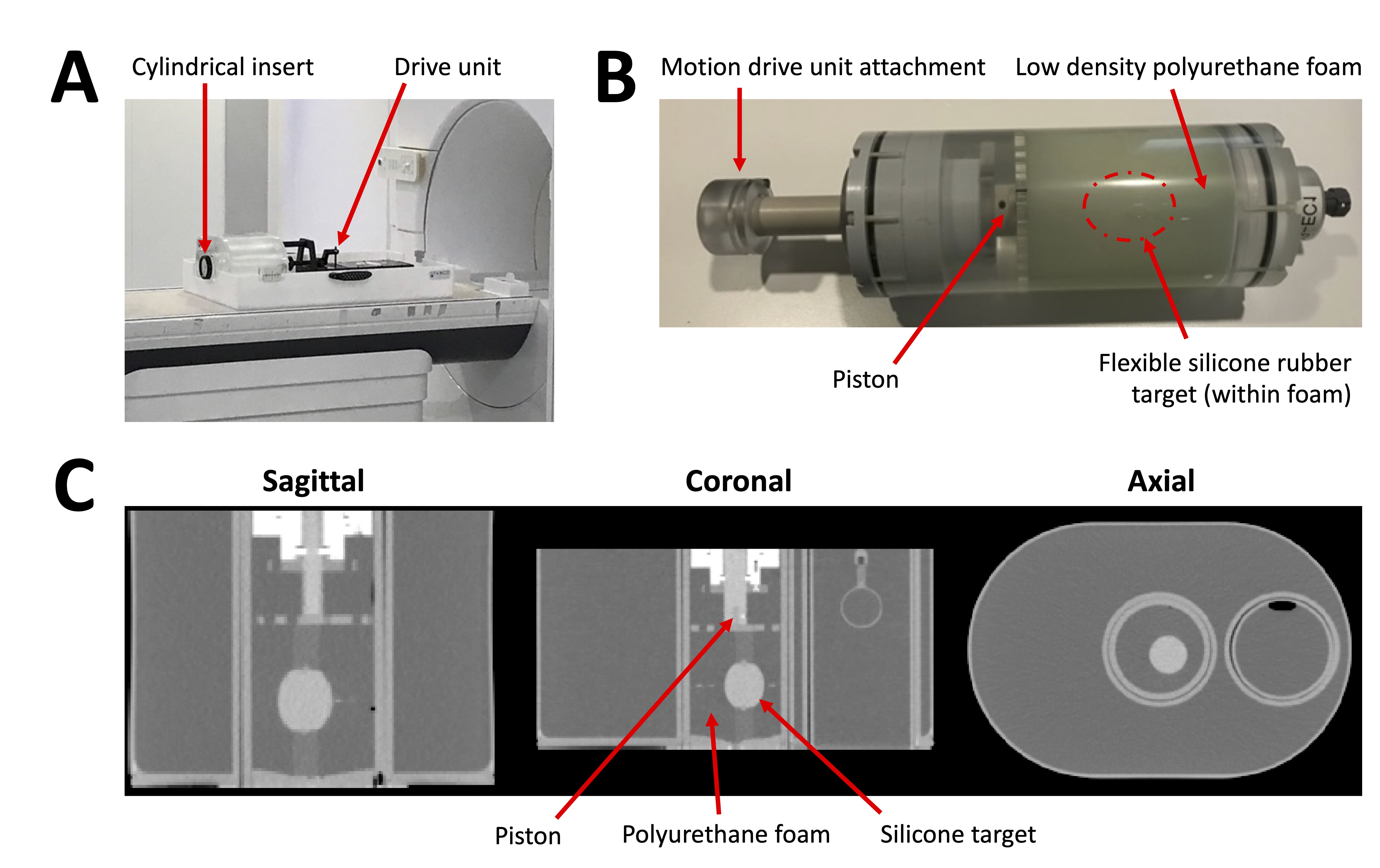
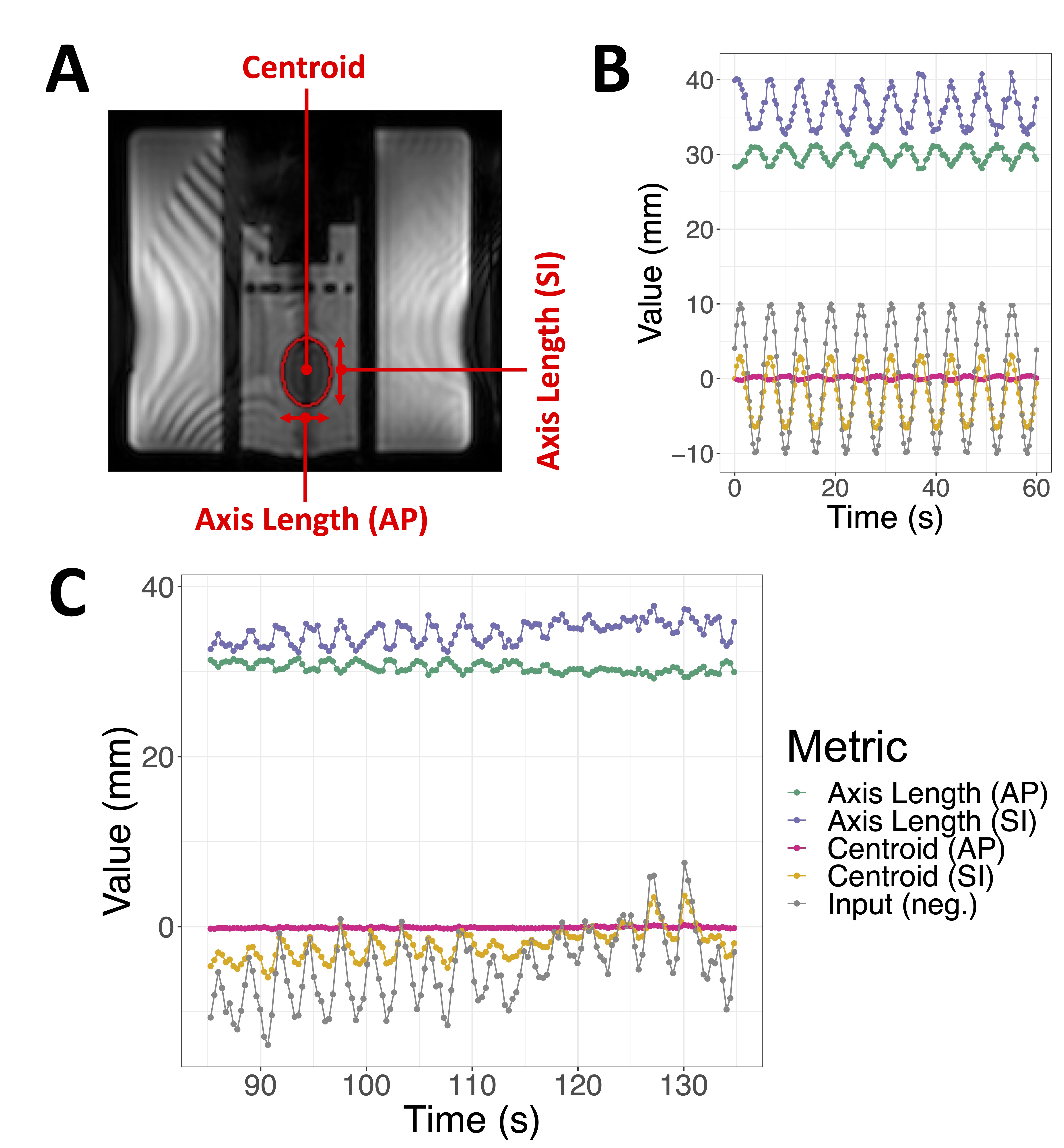
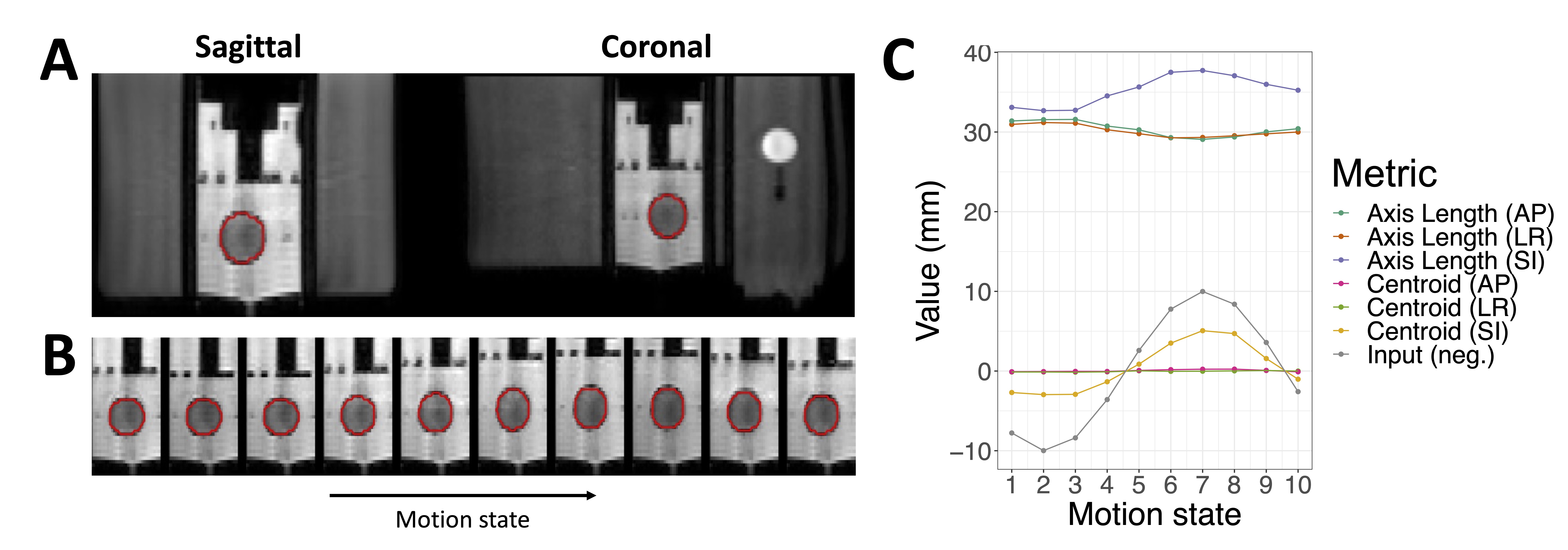
Phantom design: The phantom used for this study was the QUASAR MRI4D Motion Phantom (Modus Medical Devices, London, Canada), which comprises a cylindrical insert within a body frame attached to a drive unit (Figure 1A). A piezoelectric motor within the drive unit causes translation of the cylindrical insert, resulting in motion in the superior-inferior direction. The “Deformable Target Insert” used in this study comprises a piston that compresses a block of polyurethane foam containing an ellipsoidal silicone rubber target (Figure 1B).7 The position of the piston is set by an input waveform (Figure 2B,C).MR imaging: The phantom was scanned on a 1.5T MR-Linac (Unity, Elekta). The insert was driven with four waveforms: two 10mm-amplitude sinusoidal waveforms with frequencies of 10 and 15 cycles-per-minute, and two irregular waveforms (“irregular 1” and “irregular 2”) meant to recapitulate patient motion. Sagittal balanced steady-state free precession single-slice cine scans were acquired for all four waveforms (TR/TE=2.9/1.45ms, voxel size=3.0⨉3.0⨉5.0mm3, FOV=400⨉424⨉5mm3, scan time=3.0min, dynamics=500). A self-gated 3D golden-angle radial stack-of-stars (“3DVane”) sequence was acquired for the sinusoidal waveforms (TR/TE=3.2/1.0ms, voxel size=1.7⨉1.7⨉3.0mm3, FOV=500⨉500⨉220mm3, scan time=5.0min). The 3DVane sequence was reconstructed offline into 4D (3 spatial + 1 time) images with 10 motion states.8
CT imaging: The phantom was set to five static positions (-15, 0, 5, 10, 15mm) and 3D helical CT (Brilliance Big Bore, Philips) was acquired at each position (tube current=413mA at 120kVp, voxel size=1.2⨉1.2⨉1.5mm3, FOV=600⨉600⨉153mm3).
Mask generation: An elliptical mask of the silicone target was created for each frame of each scan using linear least-squares fitting to an intensity-threshold-generated mask,9–11 with the target volume constrained to a constant (16.84 cm3, determined from CT). The left-right and anterior-posterior dimensions were assumed equal for the cine scans (see Figure 3C). The centroid and axis lengths (“ellipsoid parameters”) in the left-right (LR), anterior-posterior (AP), and superior-inferior (SI) dimensions were extracted for statistical analysis.
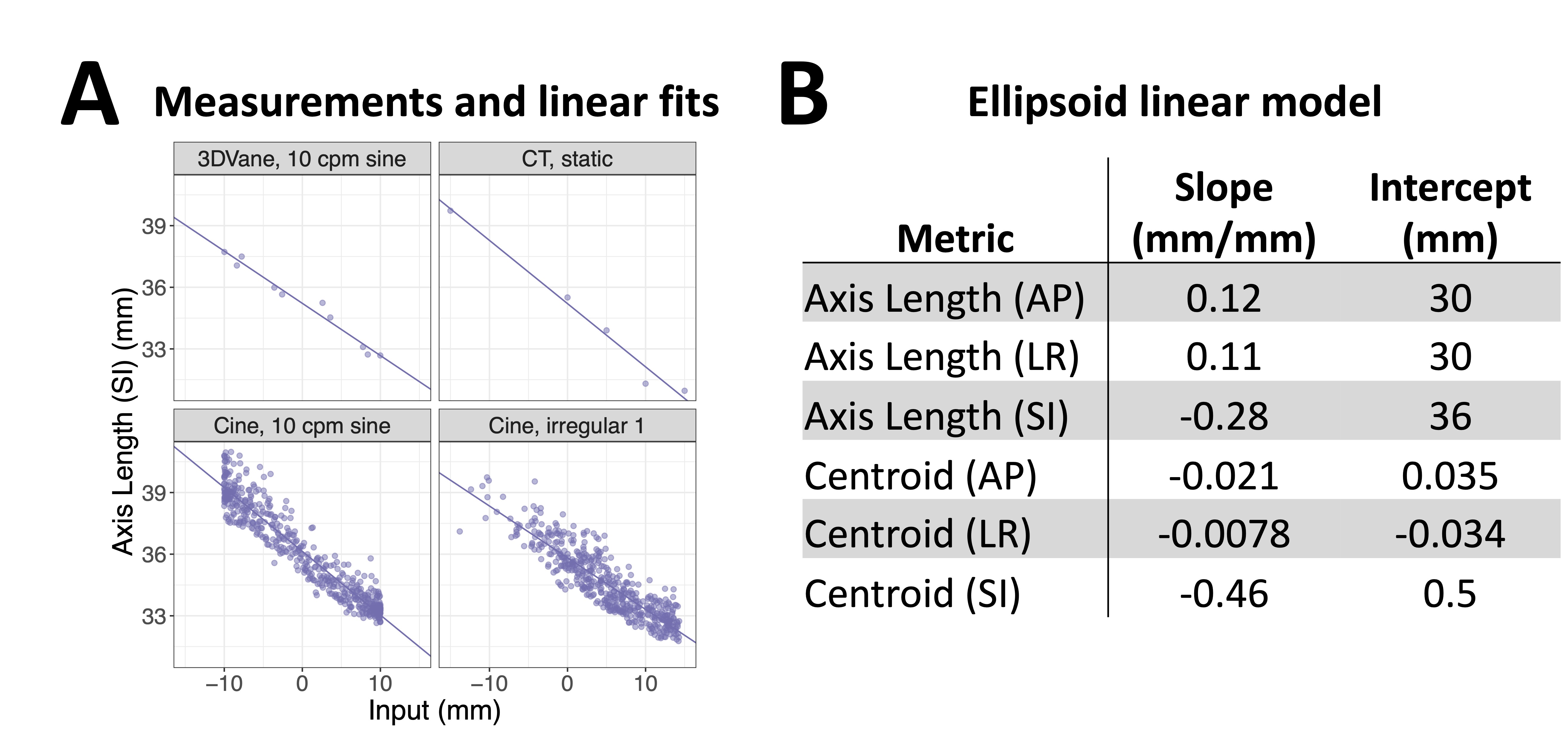
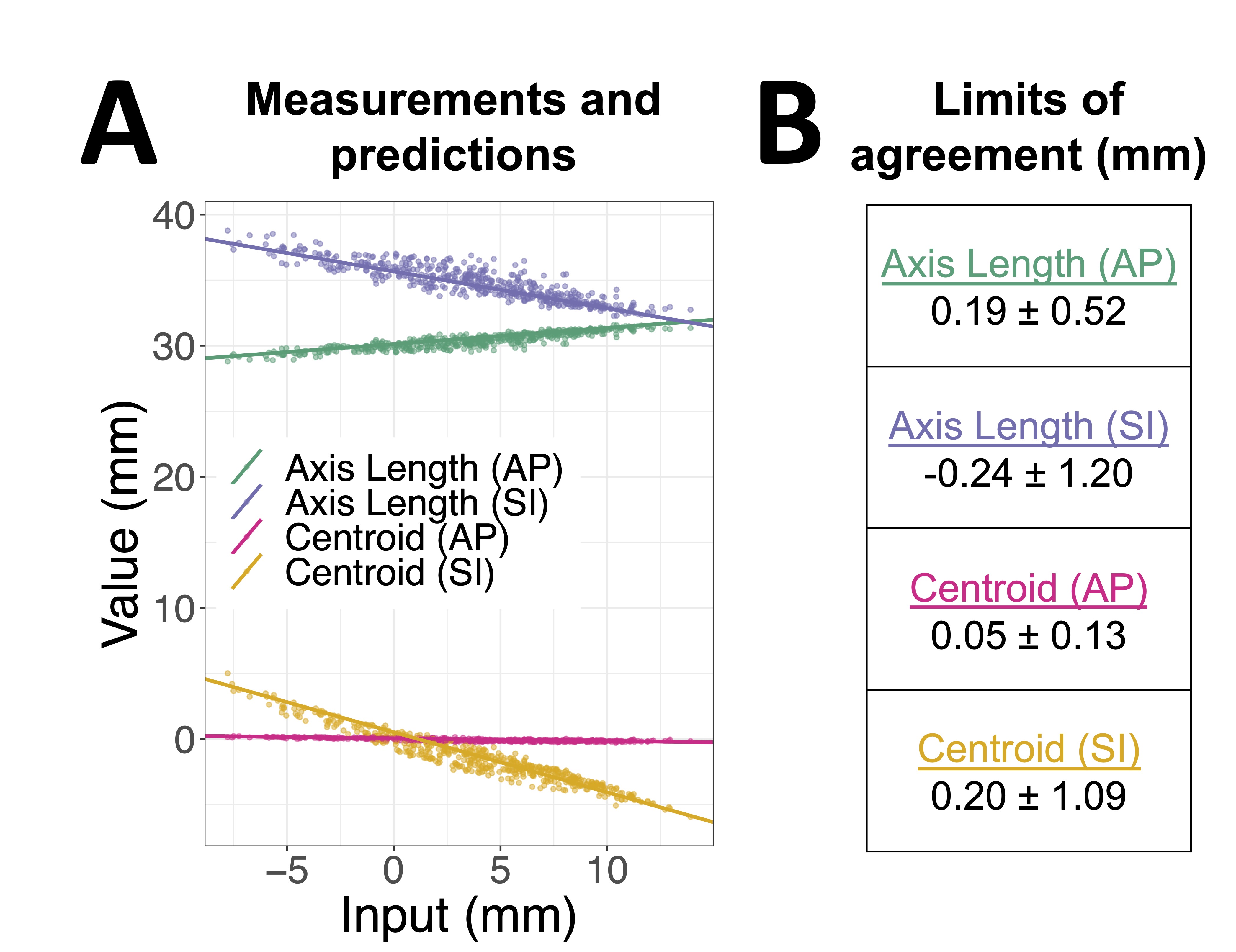
Statistics: For each scan, a line was fitted to the relation between the input and each ellipsoid parameter. The slopes and intercepts were saved. Positive inputs corresponded to compression in the superior-inferior direction. To create a single linear model, the mean slope and intercept were computed over all scans (cine, 3DVane, CT) except the cine scan with the irregular 2 input; its values were predicted from the linear model. The predictions were compared to the ground truth by calculating the mean difference and limits of agreement, i.e., the range in which 95% of the differences would be expected to lie (Bland-Altman analysis).12
Results
Examples of the ellipsoid parameters and input waveforms over time are shown in Figures 2,3. The ellipsoid parameters as a function of input showed good linearity (Figures 4A,5A). The full linear model is shown in Figure 4B. The predictions and errors of the linear model for the cine scan with irregular 2 input are shown in Figure 5. The model predicted the ellipsoid parameters within approximately a millimeter; the greatest uncertainty was in the superior-inferior axis length (-0.24±1.20mm limits of agreement).Discussion and Conclusion
Real-time adaptive radiotherapy plans could be evaluated by acquiring a dynamic scan in a patient to extract a tumor motion profile and shape, creating a patient-specific tumor model, then recreating the deformable tumor motion in a phantom. The appropriate selection of the phantom's drive unit input would be computed by inverting the input-target geometry relationship determined from the method described here. One limitation is that simple shapes (e.g., ellipsoids) will not capture the geometry of real tumors. The error introduced by this approximation should be evaluated in future studies.Acknowledgements
We gratefully acknowledge Modus Medical Devices for providing the Deformable Target Insert as part of an NSERC Alliance (ALLRP 570661 - 21) and Ontario Centre of Innovation grant (34619).References
1. Uijtewaal P, Borman PTS, Woodhead PL, et al. First experimental demonstration of VMAT combined with MLC tracking for single and multi fraction lung SBRT on an MR-linac. Radiother Oncol. 2022;174:149-157. doi:10.1016/j.radonc.2022.07.004
2. Glitzner M, Woodhead PL, Borman PTS, Lagendijk JJW, Raaymakers BW. Technical note: MLC-tracking performance on the Elekta unity MRI-linac. Phys Med Biol. 2019;64(15):15NT02. doi:10.1088/1361-6560/ab2667
3. Otazo R, Lambin P, Pignol JP, et al. MRI-guided Radiation Therapy: An Emerging Paradigm in Adaptive Radiation Oncology. Radiology. 2021;298(2):248-260. doi:10.1148/radiol.2020202747
4. Keall PJ, Sawant A, Berbeco RI, et al. AAPM Task Group 264: The safe clinical implementation of MLC tracking in radiotherapy. Med Phys. 2021;48(5). doi:10.1002/mp.14625
5. QUASARTM MRI4D Motion Phantom. Modus Medical Devices. Accessed September 28, 2023. https://modusqa.com/products/quasar-mri4d-motion-phantom/
6. Dynamic Thorax Phantom. CIRS. Accessed November 3, 2023. https://www.cirsinc.com/products/radiation-therapy/dynamic-thorax-motion-phantom/
7. Modus Medical Devices. MRI4D Deformable Target Insert Product Data Sheet. Published online 2021. https://modusqa.com/wp-content/uploads/2023/09/23-IBA-MRI4D-Deformable-Insert-Product-Sheet_PROOF-2C-2.pdf
8. Feng L, Axel L, Chandarana H, Block KT, Sodickson DK, Otazo R. XD-GRASP: Golden-angle radial MRI with reconstruction of extra motion-state dimensions using compressed sensing. Magn Reson Med. 2016;75(2):775-788. doi:10.1002/mrm.25665
9. Rosin PL. A note on the least squares fitting of ellipses. Pattern Recognit Lett. 1993;14(10):799-808. doi:10.1016/0167-8655(93)90062-I
10. Gal O. fit_ellipse. Published online 2003. https://www.mathworks.com/matlabcentral/fileexchange/3215-fit_ellipse
11. Petrov Y. Ellipsoid fit. Published online 2015. https://www.mathworks.com/matlabcentral/fileexchange/24693-ellipsoid-fit
12. Giavarina D. Understanding Bland Altman analysis. Biochem Medica. 2015;25(2):141-151. doi:10.11613/BM.2015.015
Figures