2728
Intraoperative Neurophysiological Monitoring During MRI-Guided Procedures: RF-Heating Risk Considerations1Radiology, Mayo Clinic, Rochester, MN, United States, 2Neurology, Mayo Clinic, Rochester, MN, United States
Synopsis
Keywords: MR-Guided Interventions, Safety
Motivation: Neuromonitoring is critical during interventions near nerves. During MRI-guided interventions, a conventional system using metallic electrode needles has been used clinically, since MRI-conditional neuromonitoring systems are currently unavailable. This introduces elevated RF-heating risk.
Goal(s): To identify factors that contribute to RF-heating of neuromonitoring electrodes and strategies to mitigate the risk.
Approach: Neuromonitoring electrodes were inserted into porcine tissue and imaged with various clinically relevant MRI sequences for various neuromonitoring equipment configurations with high RF-heating risks. Temperatures were recorded using fiber-optic sensors.
Results: Substantial temperature elevations were observed during MRI, and several RF-heating mitigation strategies were identified to enable neuromonitoring during MRI-guided procedures.
Impact: The identified electrode RF-heating mitigation strategies can significantly reduce the RF-heating risk during MRI-guided ablations where neuromonitoring is critical. Understanding factors affecting RF-heating can also help identify high-risk procedures and guide risk-benefit analysis.
Introduction
Intraoperative neuromonitoring (IONM) is critical to reduce neural injury when ablating lesions near nerves and has been introduced into MRI-guided ablations [1, 2]. As there are no MRI-conditional IONM systems currently available, a conventional neuromonitoring system with metallic needle electrodes has been tested for use under specific conditions [2]. Generalizing the use of IONM to wider use conditions is needed; however, the risk of radiofrequency (RF)-heating of electrodes in certain configurations can be significant. This work further investigates the factors contributing to RF-heating risk during IONM and presents several strategies to enable IONM during MRI-guided ablation even for challenging configurations.Methods
Experiments with ex vivo porcine tissue were performed on a 1.5 T scanner (Ingenia, Philips Healthcare, Best, Netherlands) using a conventional IONM system (Cascade Pro, Cadwell, Kennewick, WA). One IONM use scenario with high RF-heating risk was monitoring MRI-guided ablation of a vascular malformation in the right shoulder near the brachial plexus, and was simulated with porcine tissue fashioned to mimic a head, shoulders, and arms (Figure 1a). One pair of stimulator electrodes was inserted in the “head,” and four pairs of recording electrodes were inserted into the left and right “shoulders,” right “arm,” and “wrist.” A temperature sensor was attached to each recording electrode to track temperature at the tissue surface. The recording electrode wires were routed either along the two sides of the bore, or along the middle line of the patient table at different heights. By default, the image volume was centered at the “shoulder” level.With the wires in the “Large” position (Figure 1b), the image volume was shifted in 5 cm increments in the superior/inferior direction to study the impact of wire lengths within the MRI bore on RF-heating. At the worst heating configuration, the impact of local tissue property was investigated by moving electrode #2 in Figure 1a from a location undergone multiple tests to a “fresh” location ~1 cm away without moving anything else. To investigate the impact of connection to the IONM system, experiments in the “Sides” configuration with image volume at “shoulder” level were repeated with the electrode wires connected to/disconnected from the extender pod connected to the IONM system. The channels the electrodes were plugged into were also swapped in experiments to study whether that had any impact on RF-heating.
For imaging, a fast-spin-echo (FSE) sequence (specific absorption rate (SAR): 1.9 W/kg) was used unless otherwise specified. To examine the dependence of heating on SAR, a lower-SAR (0.9 W/kg) FSE sequence as well as a gradient-echo (GRE) sequence (SAR <0.1 W/kg) were also used. All sequences had a scan time of ~2 minutes.
Results
Figure 2 shows temperature elevations during imaging for all recording electrodes in one of the worst-case scenarios investigated. Temperature elevations up to 63.9 °C were observed and varied significantly among different electrodes. Relocating electrode #2 to a slightly different position ~1 cm away resulted in a dramatic decrease in heating, with other unmoved electrodes exhibiting different changes in temperature elevation as well. Figure 3 shows that maximum temperature elevations of electrode #2 increased as the wires moved away from the center of the scanner bore. Temperature elevations for the “Large” and “Sides” configurations were comparable. Figure 4 shows that maximum temperature elevations increased as wire length within the bore increased. In Figure 5, the two FSE series showed temperature elevations that were approximately proportional to SAR. The GRE sequence resulted in negligible heating.Disconnecting electrode wires from the IONM system resulted in up to a 30% change in electrode temperatures (~6° C), with temperature elevations either increasing or decreasing for each individual electrode. Altering electrode connections (swapping or disconnecting a subset) at the extender pod also caused changes in the recorded temperature on each electrode and relative to other electrodes.
Discussion
Significant RF-heating at the IONM electrode insertion locations was demonstrated in the ex vivo experiments. RF-heating was generally more severe with wires closer to the scanner bore, longer wire lengths within the scanner bore, and higher SAR sequences. Additionally, local tissue properties and inter-electrode interactions in both tissue and the IONM system had substantial impacts on RF-heating. Using a GRE sequence with less than 0.1 W/kg SAR resulted in negligible temperature elevations even with the relatively high-risk “Large” wire configuration.Conclusion
The temperature elevation on IONM electrodes was demonstrated to be dependent on the imaging sequence SAR and wire configurations within the scanner bore. Using optimal wire routing along with an extremely low-SAR sequence can significantly reduce the RF-heating risk during MRI-guided ablations with IONM monitoring.Acknowledgements
No acknowledgement found.References
1. Kurup AN, Morris JM, Boon AJ, Strommen JA, Schmit GD, Atwell TD, Carter RE, Brown MJ, Wass CT, Rose PS, Callstrom MR. Motor Evoked Potential Monitoring during Cryoablation of Musculoskeletal Tumors. J Vasc Interv Radiol, 2014. 25(11): 1657-1664.
2. Thompson SM, Gorny KR, Koepsel EMK, Welch BT, Mynderse L, Lu A, Favazza CP, Felmlee JP, Woodrum DA. Body interventional MRI for diagnostic and interventional radiologists: current practice and future prospects. Radiographics, 2021. 41(6): 1785-1801.
Figures
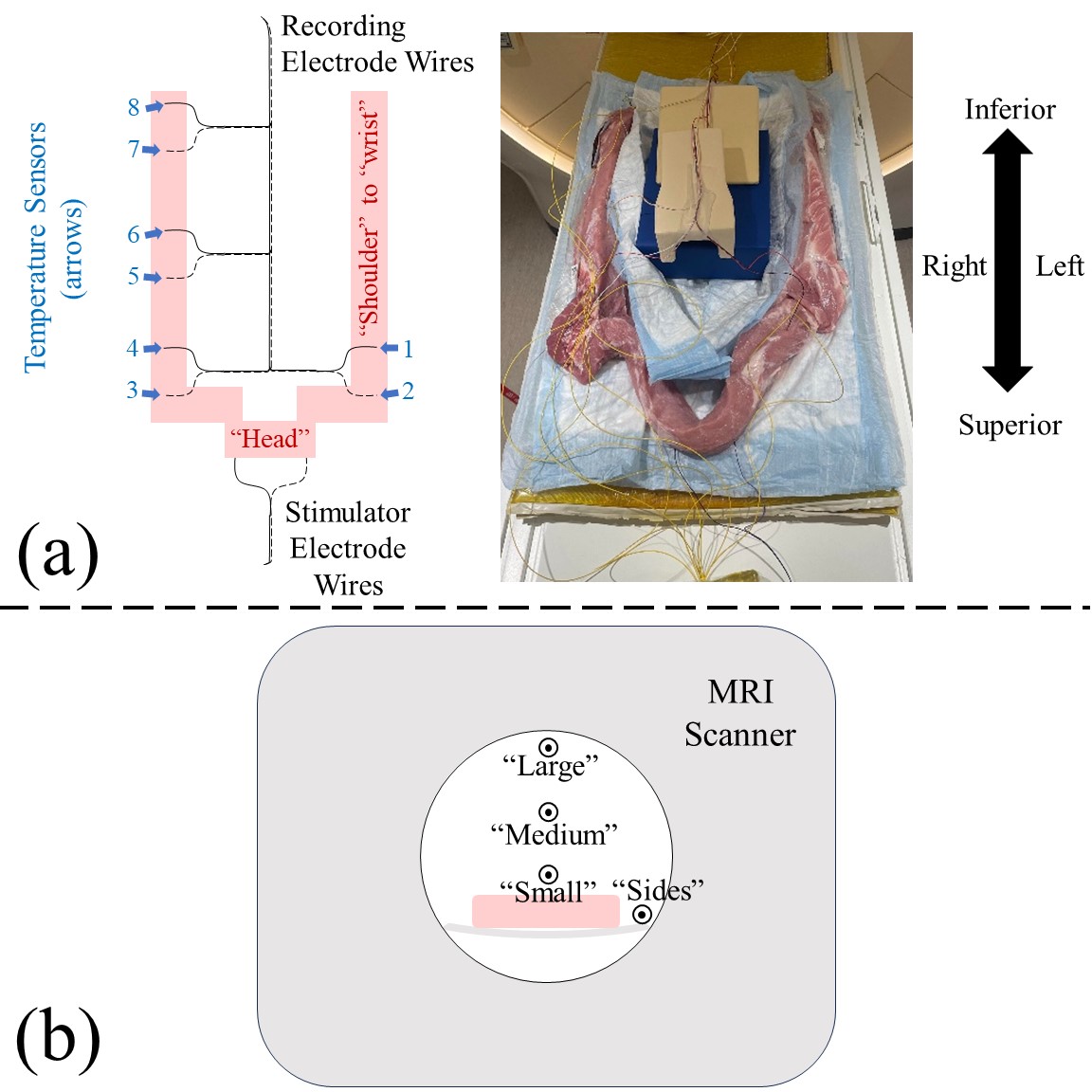
Fig. 1. (a) Experimental setup with porcine tissue to mimic a clinical scenario. Eight fiber optic temperature sensors were attached to four pairs of recording electrodes. (b) Axial cross-section showing four wire configurations, where “Large,” “Medium,” and “Small” roughly correspond to different patient sizes if the wires were routed along the middle of the patient table; the “Sides” configuration corresponds to routing the wires along the two sides of the patient table.
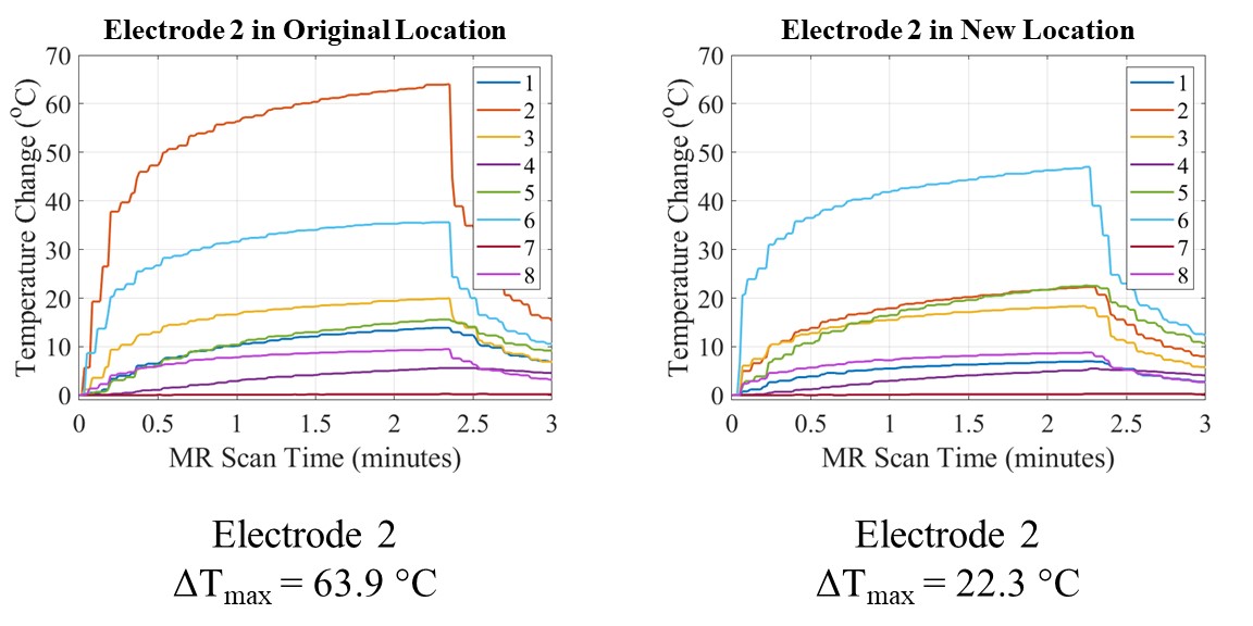
Fig. 2. (Left) Representative electrode temperature elevation curves for the eight temperature sensor locations shown in Figure 1a. (Right) Needle electrode 2 was moved from its original location to a new tissue location ~1 cm away. A dramatic decrease in heating is seen on electrode #2 while other unmoved electrodes also exhibited changes in temperature elevation.
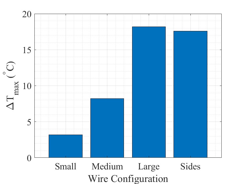
Fig. 3. Maximum temperature elevations of electrode #2 during MR scanning for different wire configurations roughly corresponding to different patient sizes.
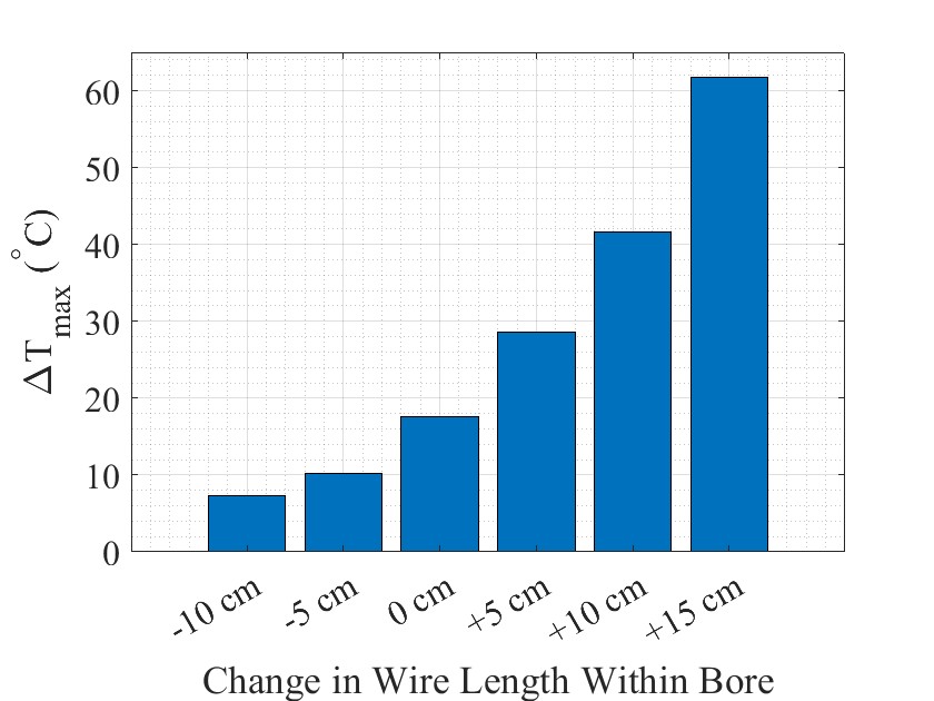
Fig. 4. Maximum electrode temperature elevations for scans with different electrode wire lengths within the bore. “0 cm” change in wire length within bore corresponds to the imaging plane centered at the shoulders.
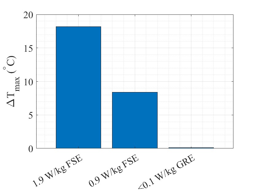
Fig. 5. Maximum temperature elevations for the “Large” patient configuration with different pulse sequences.