2727
Interactions and heating time-course of cerebral aneurysm flow diverters during scanning at 7 Tesla1Department of Neurosurgery, Iwate Medical University, Morioka, Japan, 2Division of Ultrahigh Field MRI, Institute for Biomedical Sciences, Iwate Medical University, Morioka, Japan
Synopsis
Keywords: Interventional Devices, Stroke, flow diverter, 7T MRI
Motivation: Adverse interactions with static magnetic fields (e.g., displacement force and torque) and radiofrequency-induced heating during MRI have been resolved for 3T MR systems, but have yet to be assessed for 7T MRI.
Goal(s): The present study aimed to assess displacement force and torque in the 7T static magnetic field and to clarify radiofrequency-induced heating during 7T MRI for two types of FDs.
Approach: This study was conducted based on the ASTM standards.
Results: Magnetic field interactions and heating on FDs during 7T MRI are acceptable from a safety perspective.
Impact: This study based on ASTM standards showed magnetic field interactions and heating on FDs during 7T MRI are acceptable from a safety perspective.
Introduction
Ultra-high-field MRI at 7 Tesla (7T) has recently received approval for both research and clinical applications by the Food and Drug Administration in the United States.1 In particular, 7T MRI offers high diagnostic capabilities and allows excellent identification and characterization of aneurysm domes and necks,2 cerebral microaneurysms,3 perforating arteries,4 and smaller peripheral blood vessels.5 These capabilities are considered comparable to those achieved with angiography using an arterial catheter6 and superior to those obtained with lower-field MRI.3,4,7 Flow diverters (FDs) have some risks as adverse interactions with static magnetic fields (e.g., displacement force and torque) and radiofrequency-induced heating during MRI. These safety issues have been resolved for 3T MR systems,8 but have yet to be assessed for 7T MRI. The present study aimed to assess displacement force and torque in the 7T static magnetic field and to clarify radiofrequency-induced heating during 7T MRI for two types of FDs.Methods
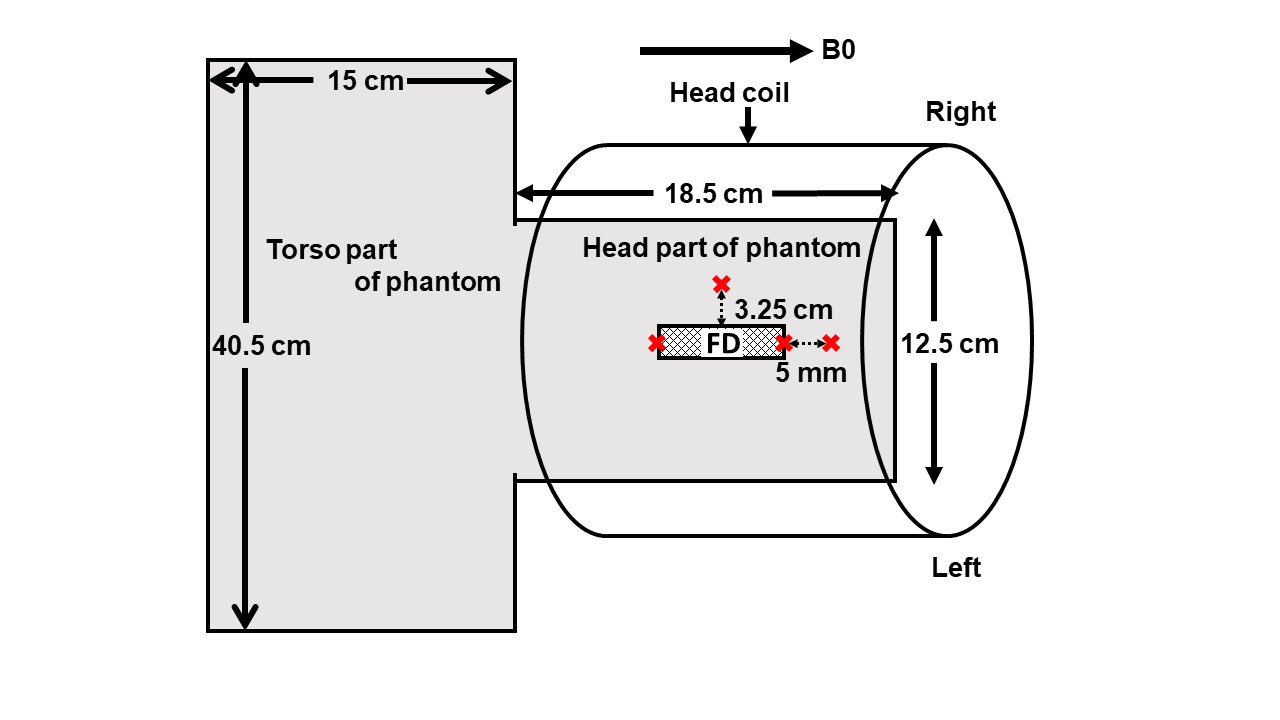
Two types of FDs for cerebral aneurysms were tested: a Pipeline Flex Embolization Device (PED) (Medtronic, Minneapolis, MN, USA); and a Flow Re-Direction Endoluminal Device (FRED) (Microvention, Tustin, CA, USA). The present study used a 7T MRI system (Discovery MR950; GE Healthcare, Milwaukee, WI, USA) with a 2-channel transmit and 32-channel receive head coil (NM008-32-7GE-MR950; Nova Medical, Wilmington, MA, USA). Displacement force and magnetically induced torque were assessed using the deflection angle method and low friction surface method, respectively (Fig 1, 2). To assess heating, each FD was set in a phantom filled with gelled saline mixed with polyacrylic acid(Fig 3) and underwent 7T MRI using a three-dimensional FSE method with the following sequence parameters: echo time, 16.4 ms; repetition time, 400 ms; field of view, 24.0 cm; slice thickness, 1.0 mm; matrix, 512×224; number of excitations, 16; number of slices, 102; scan time, 20 min, and echo train length, 24. Transmitter adjustment was performed automatically by the MRI system, with estimated head-averaged specific absorption rate (SAR) and root mean square of the MRI effective component of the B1 field (B1+rms) calculated as 0.11 W/kg and 0.41 μT, respectively. Temperature was chronologically measured at 5 mm from the cranial end of the FDs, both ends of the FDs, and 3.25 cm to the right of the isocenter as a reference using MRI-compatible fiber-optic thermometers. This study was based on the American Society for Testing and Materials (ASTM) F2052-15 “Standard Test Method for Measurement of Magnetically Induced Displacement Force on Medical Devices in the Magnetic Resonance Environment”,9 F2213-17 “Standard Test Method for Measurement of Magnetically Induced Torque on Medical Devices in the Magnetic Resonance Environment”,10 and F2182-19e2 “Standard Test Method for Measurement of Radio Frequency Induced Heating On or Near Passive Implants During Magnetic Resonance Imaging”.11Results
For displacement force, the deflection angle was 0° and the displacement force was undetectable inall three measurements for each FD. For magnetically induced torque, the repose angle was 24° and each FD remained motionless when the test fixture was rotated in 45° increments around the isocenter until a full 360° of rotation had been completed. Temperature was successfully measured at all time points. The actual averaged SAR measured for each 6-min during MRI on the scanner console was 2.0 W/kg. This value was higher than estimated head-averaged SAR (0.11 W/kg) calculated before measuring the temperature of the FD, but was close to the 3.2 W/kg proposed as the upper limit by the International Electrotechnical Commission.13Maximum temperature increases at all locations for the PED and FRED ranged from +0.1°C to +0.6°C (+0.3 ± 0.1°C) and from +0.2°C to +0.6°C (+0.3 ± 0.1°C), respectively.
Displacement force was undetectable for each FD. For magnetically induced torque, each FD remained motionless. Maximum temperature increases at all locations for the two types of FDs ranged from +0.1°C to +0.6°C.
Discussion
The present study demonstrated that displacement force and magnetically induced torque in the 7T static magnetic field were undetectable, and radiofrequency-induced heating during 7T MRI remained ≤0.6°C for both types of FDs. Guidelines published by the International Electrotechnical Commission state that radiofrequency-induced increases in body core temperature should be limited to within 1°C for the first level controlled for MRI equipment.12 The present data suggest that heating as well as magnetic field interactions for FDs in 7T MRI are acceptable from a safety perspective.Conclusion
Displacement force and magnetically induced torque in the 7T static magnetic field were undetectable, and radiofrequency-induced heating during 7T MRI remained ≤0.6°C for both types of FDs, suggesting that magnetic field interactions and heating on FDs during 7T MRI are acceptable from a safety perspective.Acknowledgements
No acknowledgement found.References
1. Voelker R. Twice the Power in New MRI. JAMA 2017;318:1858. doi: 10.1001/jama.2017.17120
2. Wrede KH, Matsushige T, Goericke SL, et al. Non-enhanced magnetic resonance imaging of unruptured intracranial aneurysms at 7 Tesla: comparison with digital subtraction angiography. Eur Radiol 2017;27:354–64. DOI: 10.1007/s00330-016-4323-5
3. Matsushige T, Kraemer M, Schlamann M, et al. Ventricular microaneurysms in Moyamoya angiopathy visualized with 7TMR angiography. AJNR Am J Neuroradiol 2016;37:1669–72. DOI: 10.3174/ajnr.A4786
4. Conijn MM, Hendrikse J, Zwanenburg JJ, et al. Perforating arteries originating from the posterior communicating artery: a 7.0-Tesla MRI study. Eur Radiol 2009;19:2986–92. DOI: 10.1007/s00330-009-1485-4
5. von Morze C, Xu D, Purcell DD, et al. Intracranial time-of-flight MR angiography at 7T with comparison to 3T. J Magn Reson Imaging 2007;26:900–04. DOI: 10.1002/jmri.21097
6. Wrede KH, Dammann P, Monninghoff C, et al. Non-enhanced MR imaging of cerebral aneurysms: 7 Tesla versus 1.5 Tesla. PLoS One 2014;9:e84562. DOI: 10.1371/journal.pone.0084562
7. De Cocker LJ, Lindenholz A, Zwanenburg JJ, et al. Clinical vascular imaging in the brain at 7T. Neuroimage 2018;168:452–58. DOI: 10.1016/j.neuroimage.2016.11.044
8. Karacozoff AM, Shellock FG, Wakhloo AK. A next-generation, flow-diverting implant used to treat brain aneurysms: in vitro evaluation of magnetic field interactions, heating and artifacts at 3-T. Magn Reson Imaging 2013 Jan;31:145-9. DOI: 10.1016/j.mri.2012.06.015
9. American Society for Testing and Materials (ASTM) International: F2052-15 Standard Test Method for Measurement of Magnetically Induced Displacement Force on Medical Devices in the Magnetic Resonance Environment. https://www.document-center.com/standards/show/ASTM-F2052. Accessed April 30, 2022
10. Standard Test Method for Measurement of Magnetically Induced Torque on Medical Devices in the Magnetic Resonance Environment. https://www.astm.org/f2213-17.html. Accessed April 30, 2022
11. American Society for Testing and Materials (ASTM) International: F2182-19e2. Standard Test Method for Measurement of Radio Frequency Induced Heating On or Near Passive Implants During Magnetic Resonance Imaging. https://www.astm.org/f2182-19e02.html. Accessed April 30, 2022
12. International Electrotechnical Commission. Particular requirements for the basic safety and essential performance of magnetic resonance equipment for medical diagnosis international standard IEC 60601 medical electrical equipment. 2015; Part 2–33. https://webstore.iec.ch/publication/22705. Accessed April 30, 2022
13. International Electrotechnical Commission. Particular requirements for the basic safety and essential performance of magnetic resonance equipment for medical diagnosis international standard IEC 60601 medical electrical equipment. 2015; Part 2–33. https://webstore.iec.ch/publication/22705. Accessed April 30, 2022
Figures
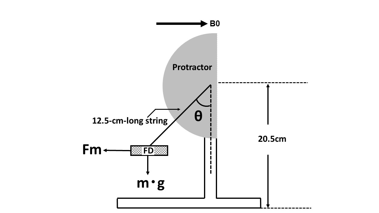
Figure 1. Schematic of a flow diverter (FD) and test fixture for measurement of displacement force. The FD is suspended from a thin, 12.5 cm string placed at the 0° indicator of the protractor. The test fixture is set parallel to a static magnetic field (B0). Displacement force is calculated from the deflection angle (θ). Fm, magnetic force; m, implant mass; g, gravity.Figure 1
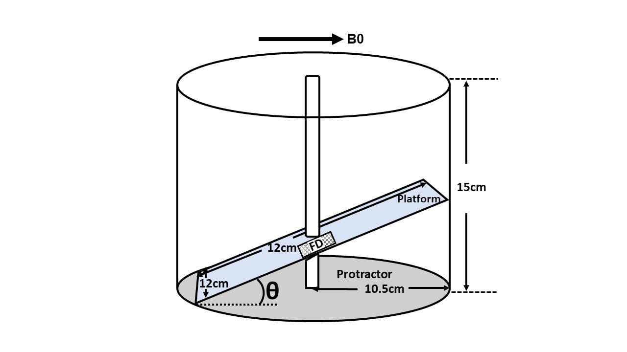
Figure 2. Schematic of an FD and test fixture for measurement of torque. The platform is tilted until the repose angle (the angle at which the device is on the verge of sliding, θ) is reached. The test fixture is rotated in 45° increments around the isocenter until a full 360° of rotation has been completed.