2723
Scan, Aim, Go: A Compact Brain Drill Guide for Accelerating Minimally-Invasive Neurosurgeries1Medical Physics, University of Wisconsin at Madison, Madison, WI, United States, 2ImgGyd, LLC, Middleton, WI, United States, 3Neurosurgery, University of Wisconsin at Madison, Madison, WI, United States, 4Waisman Center, University of Wisconsin at Madison, Madison, WI, United States, 5Biomedical Engineering, University of Wisconsin at Madison, Madison, WI, United States, 6Radiology, University of Wisconsin at Madison, Madison, WI, United States
Synopsis
Keywords: Interventional Devices, Interventional Devices
Motivation: Trajectory guides for MR-guided neurosurgeries have time-consuming, complex workflows. Trajectories are oriented by iterating between imaging and device manipulation. Noniterative approaches could reduce complexity and anesthesia time.
Goal(s): To create and validate a trajectory guide that enables faster, accurate trajectory guidance in minimally-invasive neurosurgeries.
Approach: Using new hardware and software, a single scan approach was used to perform drill guidance and device insertion on phantoms and cadaver heads.
Results: The proposed methodology accurately guided needles to targets within cadaver brains using a single targeting scan. The initial design produced a radial error of 1.54±0.81mm.
Impact: The proposed device and software accelerate trajectory guidance in minimally-invasive neurosurgeries by reducing the number of acquired scans and procedural steps. This approach simplifies and accelerates procedures which minimizes time under anesthesia.
Introduction
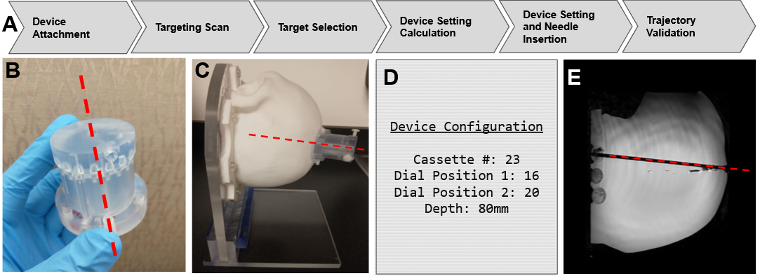
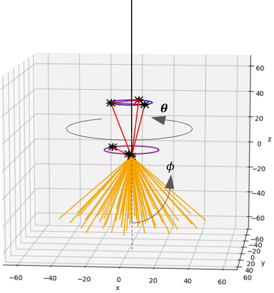
Minimally-invasive MR-guided neurosurgeries often involve extended periods of iterative scanning as the settings of trajectory-guiding tools are gradually adjusted. This leads to long procedure times which limit scanner throughput and may discourage adoption of such techniques. Leading methodologies employ a rigid stereotactic targeting frame with a channel through which a long device may be introduced through the skull to the brain1,2. Prescriptive imaging infers the trajectories that introduced probes will take based on the frame’s settings. Thus, it is necessary to acquire another scan each time the trajectory is adjusted. Methods that bypass this process by allowing a trajectory to be defined from a single scan would greatly accelerate the process.Here we report work with ImgGyd, LLC for development of a device, AccuGyd™, and software workflow (Figure 1), to create a locus of quantized trajectories (Figure 3). Only one scan is needed to orient the AccuGyd’s fiducials while companion software determines appropriate device settings.
Materials and Methods
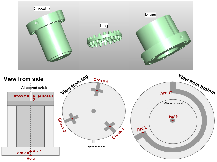
Targeting Device and Software:The proposed design (Figure 2), is cylindrical with 3 major components: a mount, ring, and cassette. The mount is to be rigidly attached to the skull. The cassette features a channel down its long axis, through which a catheter or other device is introduced. There are 60 different cassettes, each with a channel angled relative to the central axis (𝜙) in increments of 0.25 degrees up to 15 degrees from vertical. The ring connects the mount and cassette with an array of evenly-spaced ‘teeth’ along its top and bottom, slotting into matching indentations on the cassette and mount. Thus, the ring and cassette can be rotated with respect to the mount (𝛳), allowing for a large, but quantized, number of rotational cassette orientations. There are 23 teeth on the ring’s bottom and 17 on top. The device offers 23,460 unique trajectories across its two degrees of freedom (Cassette Number, 𝜙, and Ring Position, 𝛳). Figure 3 visualizes some trajectories.
A 3D RARE (FSE Cube) scan on a 3T GE scanner (GE Healthcare, Waukesha, WI) visualized the fiducials and target tissues. Complementary software registers the device’s fiducials, presently using manual coordinate identification, to the MR coordinate system. After a neurosurgeon identifies a target in the brain, the software generates a Cassette Number, two ring positional settings, and depth of target (Fig1D). Clinicians may then place the appropriate cassette in the mount, rotate the ring to its appropriate position, and advance a device down the channel.
Phantom Validation:
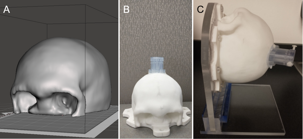
A specialized skull-shaped phantom, shown in Figure 4, was 3D printed for initial validation. A support frame held the phantom to simulate a supine patient. Filling the skull with a gelatin mixture and a set of inclusions, a human skull and brain were simulated using the inclusions as targets. Affixing the trajectory guide to the skull, a 7mm hole was drilled through, a scan was acquired, registration was performed, and 3mm borosilicate glass rods were inserted according to the settings calculated by the software. After insertion, a validation scan was run to verify the positioning of the rod and record the radial error.
Cadaver Validation:
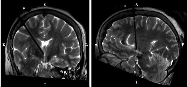
Cadaver heads were acquired for further validation. The above process was repeated with the device affixed to the cadaver via percutaneous screws to simulate a clinical procedure. Validation scans from these trials are shown in Figure 5. Five trials were performed between the two heads.
Results
From 11 trials run on the prior-described skull phantom set up, the average displacement between anticipated and actual rod positions was 1.43±0.79mm. In 5 trials run on cadaver heads, the average displacement was 1.54±0.81mm. For each series of insertion experiments, only a single registration scan was required.Discussion
The observed targeting error fell within ranges reported by clinicians currently performing these procedures: 0.6-2mm2,3. The largest loss in accuracy is attributed to errors in registration. In this work, registration points (Fig 2) were manually identified and entered into a registration calculator. The precision of identifying points was limited by the relatively small spacings of the fiducials along the device’s short axis. Future work will improve registration by automating fiducial identification and increasing fiducial spacing in the short axis.Conclusion
The device accurately guided needles to targeted locations in the brain on a level approaching commercial standards. Only a single targeting scan is required, without subsequent iterations of imaging and further manipulation of the trajectory guide. Future stages of this work will refine fiducial positioning and selection to deliver radial errors with a goal less than 1 mm.Acknowledgements
Research reported in this publication was supported by the National Institute of Neurological Disorders And Stroke of the National Institutes of Health under Award Number R43NS122713. The content is solely the responsibility of the authors and does not necessarily represent the official views of the National Institutes of Health.
The results shown here are in whole or part based upon data generated by the TCGA Research Network: http://cancergenome.nih.gov/.
References
[1] Larson PS, Starr PA, Bates G, Tansey L, Richardson RM, Martin AJ. An optimized system for interventional magnetic resonance imaging-guided stereotactic surgery: preliminary evaluation of targeting accuracy. Neurosurgery. 2012 Mar;70(1 Suppl Operative):95-103; discussion 103. doi: 10.1227/NEU.0b013e31822f4a91. PMID: 21796000; PMCID: PMC3249469.
[2] Sterk B, Taha B, Osswald C, Bell R, Chen L, Chen CC. Initial Clinical Experience With ClearPoint SmartFrame Array-Aided Stereotactic Procedures. World Neurosurg. 2022 Jun;162:e120-e130. doi: 10.1016/j.wneu.2022.02.095. Epub 2022 Feb 26. PMID: 35231619.
[3] Luciano MS, Katz M, Racine CA, Martin AJ, Markun LC, Larson PS. Clinical outcomes using ClearPoint interventional MRI for deep brain stimulation lead placement in Parkinson's disease. J Neurosurg. 2016 Apr;124(4):908-16. doi: 10.3171/2015.4.JNS15173. Epub 2015 Oct 23. PMID: 26495947.
[4] Zuley, M. L., Jarosz, R., Kirk, S., Lee, Y., Colen, R., Garcia, K., Delbeke, D., Pham, M., Nagy, P., Sevinc, G., Goldsmith, M., Khan, S., Net, J. M., Lucchesi, F. R., & Aredes, N. D. (2016). The Cancer Genome Atlas Head-Neck Squamous Cell Carcinoma Collection (TCGA-HNSC) (Version 6) [Data set]. The Cancer Imaging Archive. https://doi.org/10.7937/K9/TCIA.2016.LXKQ47MS
[5] Clark, K., Vendt, B., Smith, K., Freymann, J., Kirby, J., Koppel, P., Moore, S., Phillips, S., Maffitt, D., Pringle, M., Tarbox, L., & Prior, F. (2013). The Cancer Imaging Archive (TCIA): Maintaining and Operating a Public Information Repository. In Journal of Digital Imaging (Vol. 26, Issue 6, pp. 1045–1057). Springer Science and Business Media LLC. https://doi.org/10.1007/s10278-013-9622-7
Figures