2700
Four-channel receiver coil array for focused ultrasound spine imaging1Physical Sciences Platform, Sunnybrook Research Institute, Toronto, ON, Canada, 2Department of Medical Biophysics, University of Toronto, Toronto, ON, Canada
Synopsis
Keywords: MR-Guided Focused Ultrasound, RF Arrays & Systems, Focus Ultrasound
Motivation: MRI with the focused ultrasound treatment on the spine has low image quality, presumably due to a tailored receiver coil array.
Goal(s): A receiver coil array for 3T MRI is developed to image the spine of a large animal during focused ultrasound (FUS) treatment using a flat, large-aperture (25 cm diameter) phased array transducer.
Approach: A 4-channel receiver coil array was built with a housing curved to conform to the back of the specimen.
Results: Structural images with T1- and T2-weighted contrast confirmed an SNR gain of approximately 50% using this coil array compared with images acquired using a body coil.
Impact: The FUS-compatible spine MRI receiver coil array will enhance visualization of BSCB openings. As a clinical application, this coil array will also alleviate intraprocedural imaging challenges.
Introduction
The blood-spinal cord barrier (BSCB) can be opened non-invasively in pigs using focused ultrasound (FUS) 1. MRI can non-invasively monitor this effect. In concurrent FUS and MRI for BSCB opening, the geometry of the spine necessitates a posterior FUS approach, where the subject must lie supine on the FUS platform for treatment. This supine positioning also suppresses breathing motion. However, existing spine coil arrays comprise partially overlapping coils to minimize mutual coupling 2. These designs do not consider the space needed by a FUS transducer and a water buffer in a practical setup. Existing flex or cardiac coils placed on the chest can be used, but the distance between the coil and the spine leads to poor SNR. Alternatively, a single loop coil surrounding the FUS array aperture can be used for MRI detection. However, the large diameter needed to accommodate the FUS array hinders the resulting coil performance.Here, we present the development of a 4-channel receiver coil array at 3T for spinal FUS with a flat large aperture (25 cm diameter phased array transducer). With multiple localized detections of MRI signals and a conformed shape of the array to the back, this coil array was tested on large animals (pigs, ~40 kg) to evaluate its SNR performance.
Methods
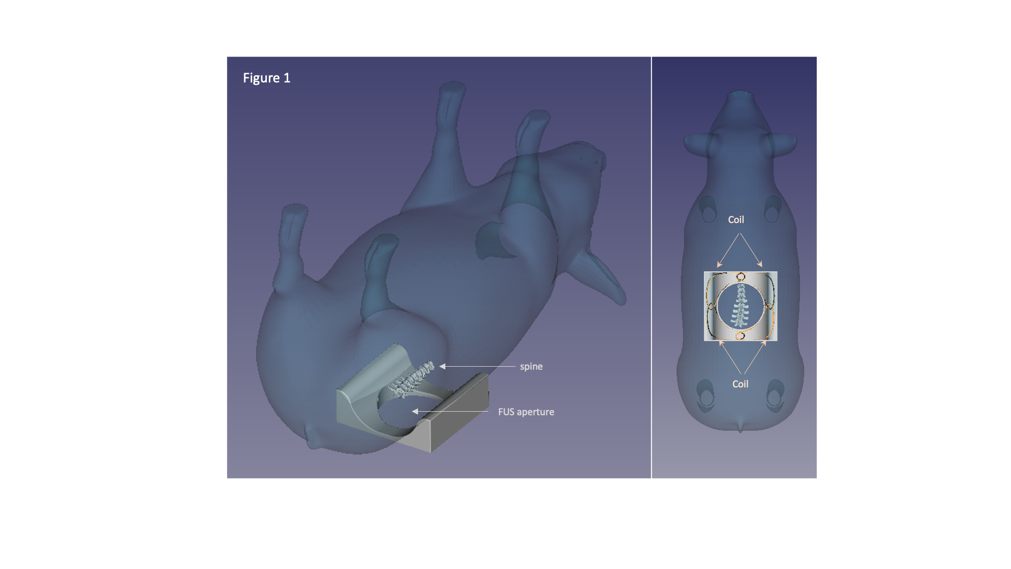
Radiofrequency (RF) coils were built for 3 T MRI (Prisma, Siemens, Erlangen, Germany). The receiver array consisted of four coils (~58 cm in length) distributed surrounding the opening of the acoustic coupling water bath pad, for integrating the FUS device (Arrayus Technologies, Ontario, Canada). This FUS-compatible 4-channel (FUS-4ch) coil array has a housing curved to conform to the back of the specimen. RF coils were constructed with distributed non-magnetic and variable capacitors (Voltronics, Denville, NJ, USA) for resonance frequency tuning. The coil used 16 AWG tinned copper wire. A front-end circuit board consisting of a PIN diode (M/A-COM Tech., MA, USA), an inductor (Coilcraft, IL, USA), and a matching network with a capacitor and two inductors was connected to the coil. Coils in the 4-channel coil array were decoupled by overlapping neighboring RF coils to minimize the mutual inductance 2. We used pre-amplifiers to further decouple next-nearest neighbouring coils 2. The mechanical housing of the coil array was made by a 3D printer using polycarbonate (PC-ISO) plastic (FORTUS, Eden Prairie, MN, USA).Coupling between channels of a coil array was quantified by a noise covariance matrix, calculated from the acquired imaging data without any RF transmission (GRE sequence with 0o flip angle). T1-weighted (TurboFLASH respiratory-gated sequence: TI = 1200 ms; TE = 2.54 ms, slice thickness = 4 mm) and T2-weighted (3D SPACE sequence: TR = 2000 ms; TE = 81 ms, slice thickness = 2 mm) images were acquired using the FUS-4ch array and a body coil (BC) for comparison.
Results
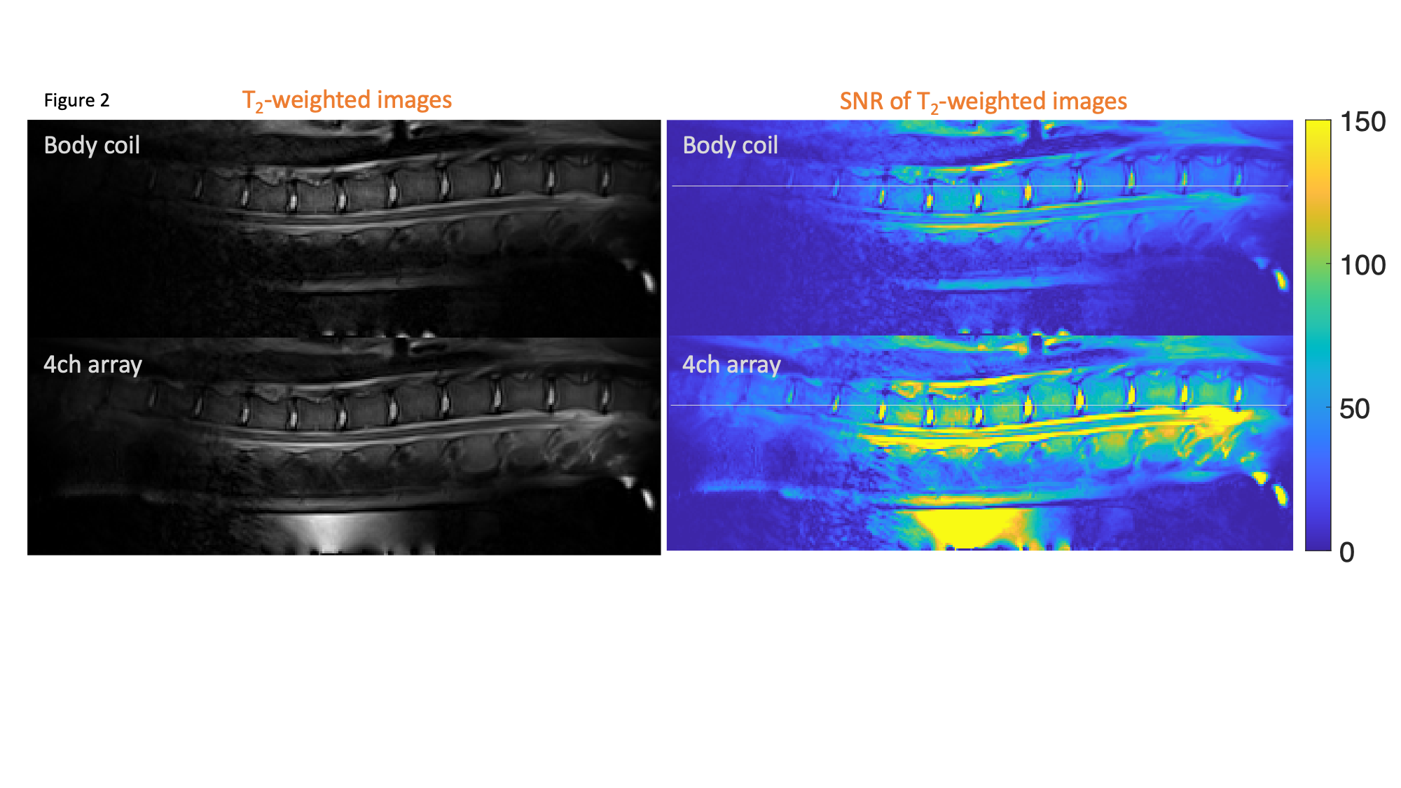
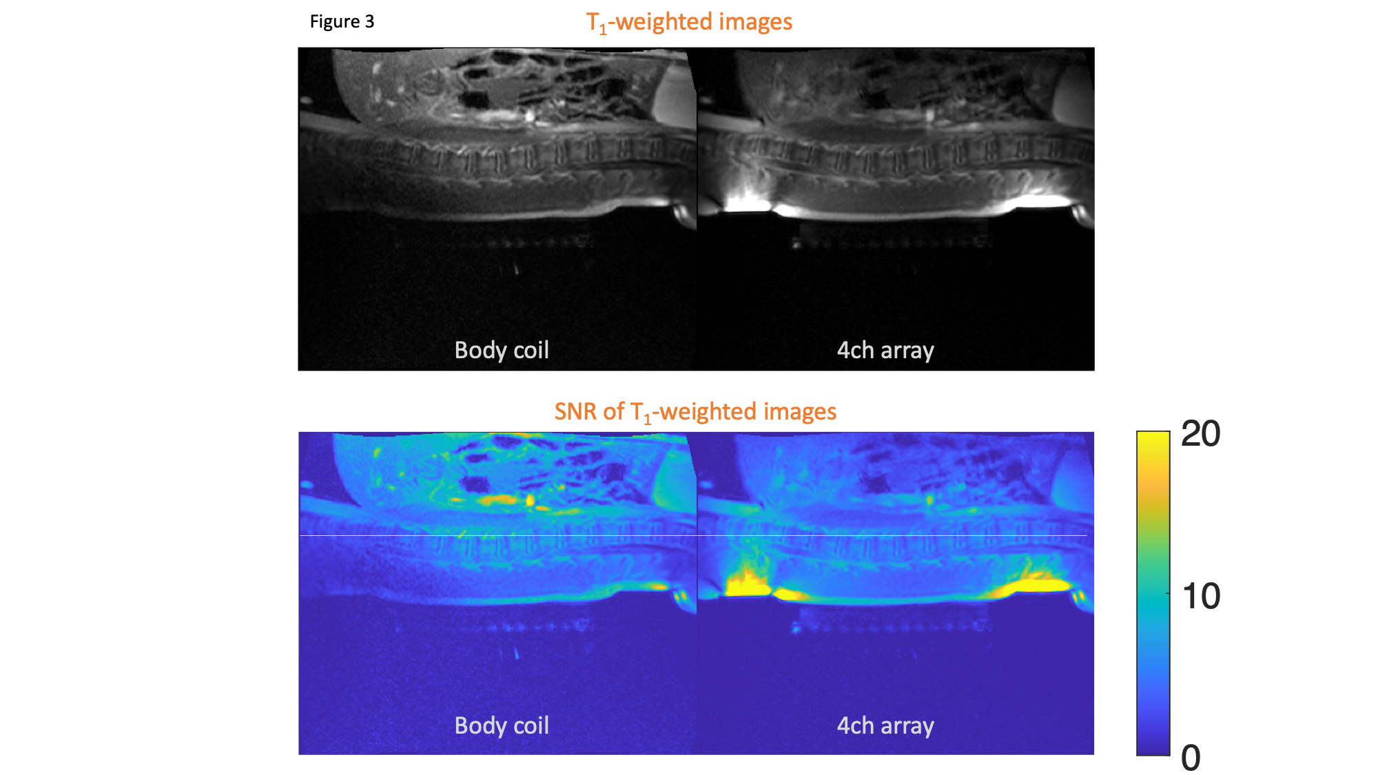
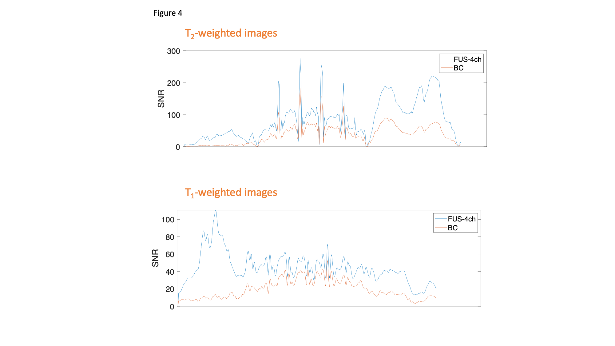
Figure 1 shows the experimental setup of the animal and coil array placement to image the lower part of the pig’s thoracic spine. The noise covariance matrix of the coil array suggested sufficient decoupling between four channels (average off-diagonal entries= 0.0096 with a maximum of 0.0111). Figure 2 and Figure 3 shows the T2-weighted images and T1-weighted images, respectively. Images using the FUS-4ch array had a stronger signal around the back and a weaker signal toward the abdomen than BC. SNR profiles in T1-weighted along the spine in images are shown in Figure 4. Around the spine, the SNR of the FUS-4ch array was approximately 157% of that of the BC (FUS-4ch: 46 ± 8 BC: 30 ± 7). In T2-weighted images (Figure 2), the SNR gain around the spine of the FUS-4ch array was about 67% of that of the BC (Figure 4. FUS-4ch: 95 ± 47; BC: 57 ± 29.)Discussion
Here, we developed a 4-channel coil array compatible with a flag large aperture (25 cm diameter) FUS phased array transducer for 3T MRI. The tailored geometry of the FUS-4ch array enabled high-SNR MRI around the spine (Figure 1). The limit of this array was the constraint of excluding any RF coil wiring passing through the FUS aperture. Different materials or thin wires may overcome this constraint to further increase the MRI SNR around the FUS aperture.This FUS-compatible spine MRI receiver coil array is expected to enable the visualization of BSCB opening with gadolinium-enhanced T1-weighted contrast MRI in large animals. This coil array is also expected to mitigate similar challenges in intraprocedural imaging in the clinical scenario.
Acknowledgements
This work was supported by the Natural Sciences and Engineering Research Council of Canada (NSERC; RGPIN-2020-05927), Canada Foundation for Innovation (38913 and 41351), Canadian Institutes of Health Research (PJT 178345 and PJT 185882), MITACS (IT25405 and Global Link fellowship) and the Canada Research Chairs program.References
- Fletcher, S.-M. P. et al. Theranostics 10, 7758–7774 (2020)
- Roemer, P. B. et al. Magn. Reson. Med. 16, 192–225 (1990)
Figures