2677
Flexible Receiver Coil Using Direct-3D-Write Technology at 0.55T1Alfred E. Mann Department of Biomedical Engineering, University of Southern California, Los Angeles, CA, United States, 2Ming Hsieh Department of Electrical and Computer Engineering, University of Southern California, Los Angeles, CA, United States, 3Stark Contrast, Erlangen, Germany
Synopsis
Keywords: Non-Array RF Coils, Antennas & Waveguides, New Devices, Flexible Electronics, 3D-Write Technology
Motivation: MRI receiver coils are often rigid thus cannot conform to every anatomy. This motivates to create flexible, robust, and easy to manufacture coils.
Goal(s): To create scalable and low-cost MRI coils using direct-3D-writing. The coils should conform to different anatomies and be robust to bending and stretching.
Approach: We utilize a fast direct-3D-write method (~8 minutes print time per coil) that uses an easy to modify coil model, and compare performance against a rigid copper coil at 0.55 Tesla.
Results: The flexible printed coil provided 1.8 times higher SNR compared to the reference copper coil due to better form-fitting.
Impact: MRI receiver coils, printed with the direct-3D-write method, can be made flexible to conform to imaging anatomy, while offering scalability and lower cost. This simplifies manufacturing and improves SNR due to better form-fitting.
Introduction
MRI receiver coils are used to capture the signal originating from excited spins within the object of interest, thus playing a key role in the signal-to-noise ratio (SNR) of resulting images1-3. Traditional coils are typically based on rigid copper because their high conductivity offers low losses, while their rigid enclosure offers a good platform for decoupling4,5. However, due to the rigidity of these coils, they are unable to conform to the imaging anatomy, resulting in sub-optimal SNR and making it difficult to study pathologies requiring imaging under different postures, such as imaging wrist movements and other musculoskeletal dynamics6,7. To address this problem, flexible coils have been developed utilizing different technologies, such as screen-printing, conductive threads, and microfluidic channels8-10. While solving many of the issues related to rigid enclosures, these methods are difficult to manufacture quickly. In this work, we demonstrate a custom-made flexible receiver coil based on highly conductive silver ink printed using state-of-the-art high-resolution direct-3D-write technology, minimizing cost and manufacturing time, while maximizing scalability.Methods
The flexible receiver coil was fabricated using a high resolution direct-3D-write printer (Voltera Nova) The coil footprint was first designed in AutoCAD (Autodesk) and then printed using a highly conductive silver nanoparticle-based ink (σ = 16.6 MS/m, ACI Materials) onto a flexible thermoplastic polyurethane (TPU) substrate. To ensure robustness against bending and mechanical stress, a serpentine design was utilized. The coil was interfaced using a clamp mechanism to a custom-made circuit board containing tuning/matching and decoupling circuitry. The fixture was connected via a coaxial cable to a pre-amplifier box (Stark Contrast). The coil was characterized using a variable network analyzer (VNA) (Keysight). The coil photographs and electrical schematics are shown in Figure 1.Evaluation experiments were performed on a 0.55T MRI system (prototype MAGNETOM Aera, Siemens Healthineers) equipped with high-performance gradients (45 mT/m amplitude, 200 T/m/s slew rate) and body-coil transmission. Imaging parameters were: 2D GRE, TR = 200 ms, TE = 5.8 ms, flip angle = 20, voxel size = 1.6 x 1.6 x 5 mm, pixel bandwidth = 130 Hz/pixel, and acquisition time of 38 s. The flexible coil was compared to a reference rigid copper coil both in flat and wrapped configurations. The coils were placed on a 500 ml water phantom as shown in Figure 2. The phantom has a 7 cm diameter to mimic approximate dimensions of a human forearm/wrist. Images were reconstructed in SNR units11. SNR efficiency was evaluated relative to the integrated body coil, allowing calculation of SNR gains for each relative to a common reference12.
Results
The flexible coil took 8 minutes to fully print and showed good tuning/matching performance with a S11 of -32 dB and adequate detuning of -50 dB as measured with a S21 measurement at 23.4 MHz. The Q factor was evaluated using a transmission S21 3-dB measurement. The unloaded Q value was 95 and the loaded value was 43, for a Q- ratio of 2.3. For the reference coil, the Q-ratio was 2.4.Figure 3 shows the GRE images and the reconstructed SNR gain maps for the flexible coil in both configurations and the reference coil. Figure 4 shows the SNR ratio for the flexible coil over the copper coil in both flat and wrapped positions. Compared to the reference coil, the flexible coil achieves a 15% lower SNR at the center, and 80% higher SNR in areas that benefit from the form-fitting wrap.
Discussion
We fabricated and evaluated the performance of a flexible coil fabricated using direct-3D-write technology printed with highly conductive silver nanoparticle-based ink. Due to lower conductivity of the silver ink, the proposed coil achieved 15% lower SNR at the center, however, it also achieved 80% higher SNR in areas where it wraps around the phantom due. This form-fitting feature is expected to be beneficial to wrist/ankle imaging since these anatomies have a similar diameter as the phantom used here.The proposed fabrication method uses Gerber files (standard format for printed circuit boards), which allows for fast customization of coil designs for different anatomies. Next steps include studying the effect of different coil characteristics on SNR, such as trace number/width. Another next step is extending to arrays, and applying to relevant clinical applications including ankle/wrist dynamic imaging, breast imaging, etc.
Conclusion
We fabricated and evaluated a flexible receiver coil based on silver nanoparticle ink. Results show that due to the form-fitting nature of the flexible coil, it is able to provide a significant SNR advantage over the rigid copper-based reference coil.Acknowledgements
We acknowledge support from USC Viterbi School of Engineering, as well as grant support from the National Institutes of Health (R01-AR078912, R21-HL159533, U01-HL167613) and National Science Foundation (Award #1828736), and research support from Siemens Healthineers.
References
1. Fujita H, Zheng T, Yang X, Finnerty MJ, Handa S. RF Surface Receive Array Coils: The Art of an LC Circuit. Journal of Magnetic Resonance Imaging. 2013;38(1):12–25. https://dx.doi.org/10.1002/jmri.24159. doi:10.1002/jmri.24159
2. Roemer PB, Edelstein WA, Hayes CE, Souza SP, Mueller OM. The NMR phased array. Magnetic Resonance in Medicine. 1990;16(2):192–225.. doi:10.1002/mrm.1910160203
3. Keil B, Wald LL. Massively parallel MRI detector arrays. Journal of Magnetic Resonance. 2013;229:75–89. https://dx.doi.org/10.1016/j.jmr.2013.02.001. doi:10.1016/j.jmr.2013.02.001
4. Darnell D, Truong T, Song AW. Recent Advances in Radio‐Frequency Coil Technologies: Flexible, Wireless, and Integrated Coil Arrays. Journal of Magnetic Resonance Imaging. 2022;55(4):1026–1042.. doi:10.1002/jmri.27865
5. Wiggins GC, Triantafyllou C, Potthast A, Reykowski A, Nittka M, Wald LL. 32‐channel 3 Tesla receive‐only phased‐array head coil with soccer‐ball element geometry. Magnetic Resonance in Medicine. 2006;56(1):216–223. https://dx.doi.org/10.1002/mrm.20925. doi:10.1002/mrm.20925
6. Mcgee KP, Stormont RS, Lindsay SA, Taracila V, Savitskij D, Robb F, Witte RJ, Kaufmann TJ, Huston J, Riederer SJ, et al.. Characterization and evaluation of a flexible MRI receive coil array for radiation therapy MR treatment planning using highly decoupled RF circuits. Physics in Medicine & Biology. 2018;63(8):08NT02. https://dx.doi.org/10.1088/1361-6560/aab691. doi:10.1088/1361-6560/aab691
7. Corea JR, Flynn AM, Lechêne B, Scott G, Reed GD, Shin PJ, Lustig M, Arias AC. Screen-printed flexible MRI receive coils. Nature Communications. 2016;7(1):10839. https://dx.doi.org/10.1038/ncomms10839. doi:10.1038/ncomms10839
8. Zhang D, Rahmat-Samii Y. A Novel Flexible Electrotextile 3T MRI RF Coil Array for Carotid Artery Imaging: Design, Characterization, and Prototyping. IEEE Transactions on Antennas and Propagation. 2019;67(8):5115–5125.. doi:10.1109/tap.2019.2891700
9. Vincent JM, Rispoli JV. Conductive Thread-Based Stretchable and Flexible Radiofrequency Coils for Magnetic Resonance Imaging. IEEE Transactions on Biomedical Engineering. 2020;67(8):2187–2193.. doi:10.1109/tbme.2019.2956682
10. Motovilova E, Tan ET, Taracila V, Vincent JM, Grafendorfer T, Shin J, Potter HG, Robb FJL, Sneag DB, Winkler SA. Stretchable self-tuning MRI receive coils based on liquid metal technology (LiquiTune). Scientific Reports. 2021;11(1).. doi:10.1038/s41598-021-95335-6
11. Kellman P, Mcveigh ER. Image reconstruction in SNR units: A general method for SNR measurement†. Magnetic Resonance in Medicine. 2005;54(6):1439–1447. https://dx.doi.org/10.1002/mrm.20713. doi:10.1002/mrm.20713
12. Muñoz F, Lim Y, Cui SX, Stark H, Nayak KS. Evaluation of a novel 8-channel RX coil for speech production MRI at 0.55 T. Magnetic Resonance Materials in Physics, Biology and Medicine. 2022;36(3):419–426.. doi:10.1007/s10334-022-01036-0
Figures
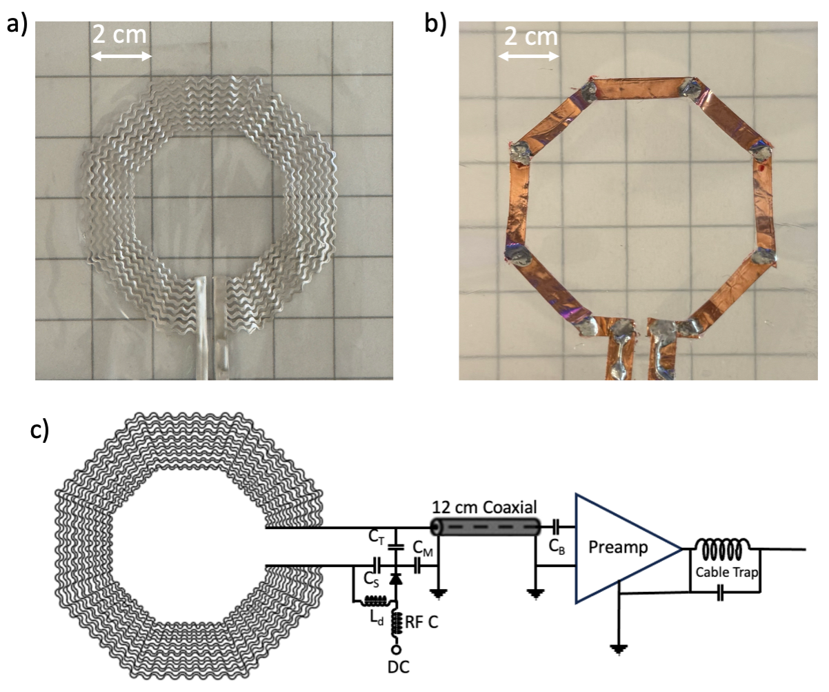
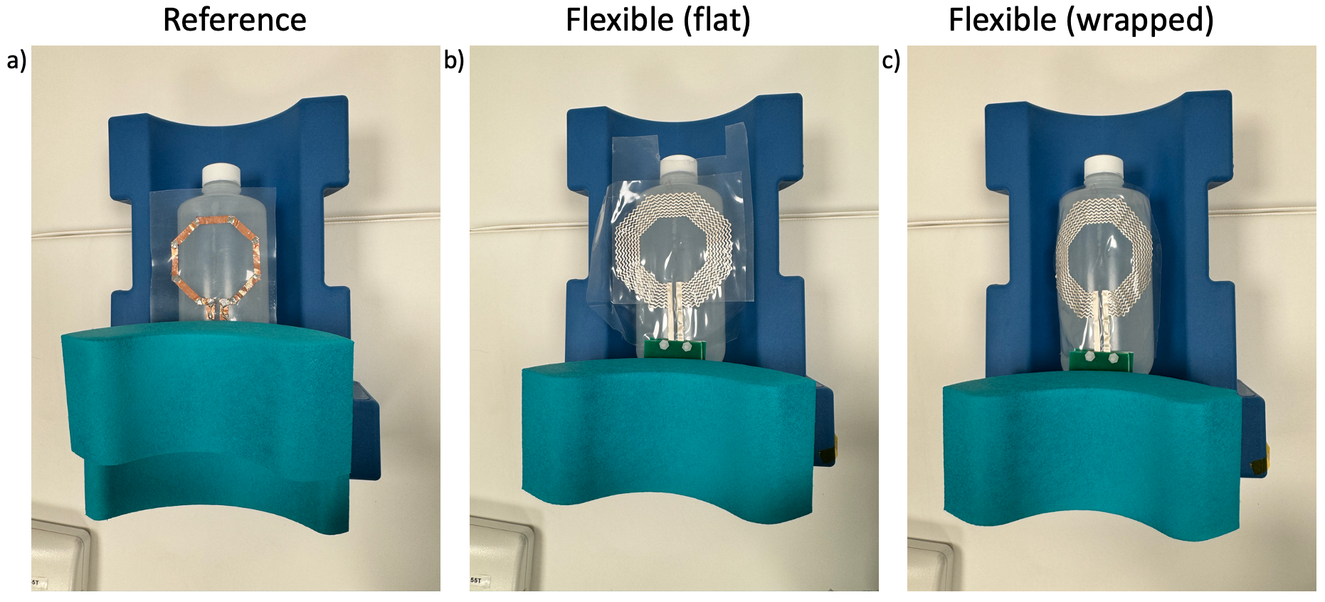
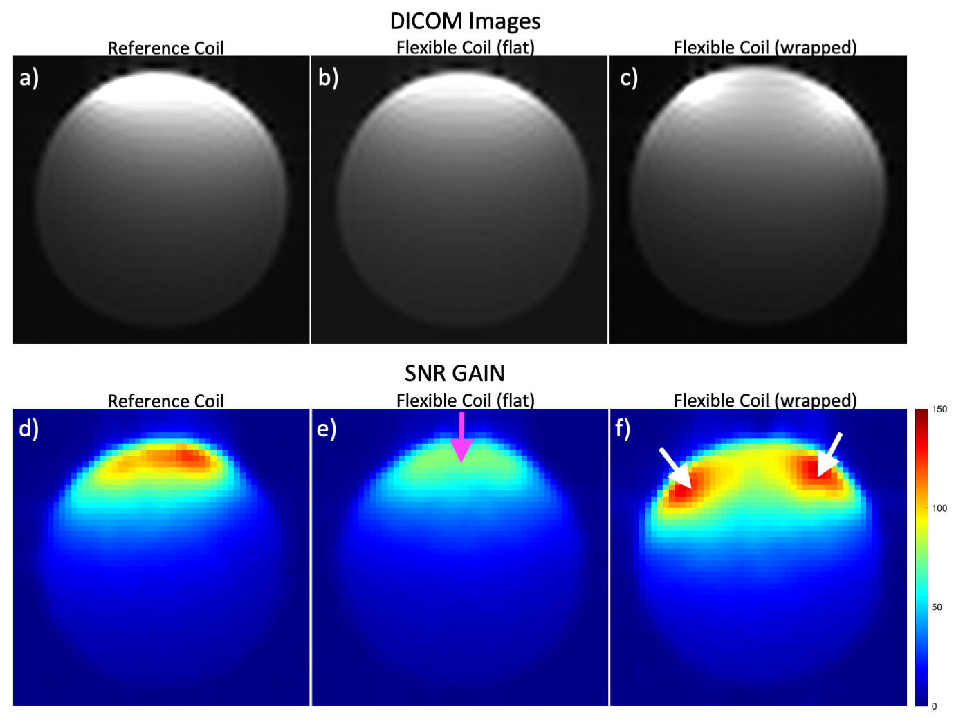
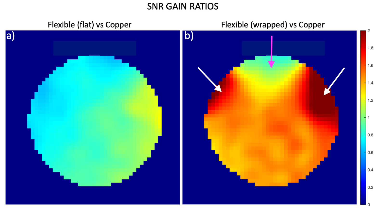
Figure 4: SNR Ratio Maps for the Flexible Coil compared to the Reference Rigid Coil. Flexible coil is evaluated in the a) flat and b) wrapped positions. The flexible coil in the center (magenta arrow) has about 15% lower SNR than the copper coil due to lower conductivity. In areas where the flexible coil can wrap around (white arrows) the flexible coil provides 80% higher SNR than the copper coil. |