2655
Motion Correction in Multi-shot Acquisitions by Removal of Motion-ridden Shots to fill with Unrolled DL Reconstruction1GE Healthcare, Bangalore, India
Synopsis
Keywords: Motion Correction, Motion Correction, Navigator, unrolled reconstruction, data consistency
Motivation: Motion is the primary reason for artifacts in MRI.
Goal(s): The proposed method is an attempt at solving motion correction problem for 2D-acquisitions by dropping motion-corrupt sections of k-space to be reconstructed in a fashion similar to under-sampled reconstruction by an unrolled DL framework.
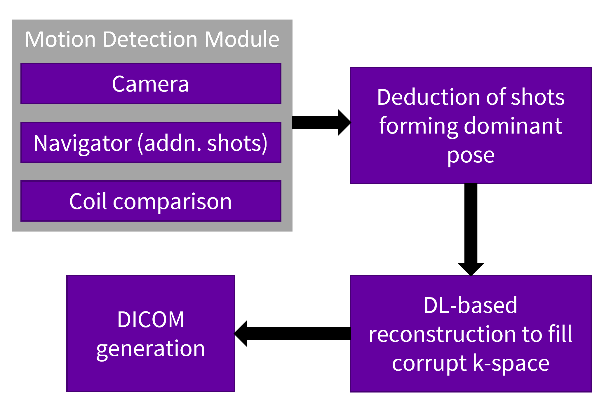
Approach: The estimation of motion-corrupt shots is proposed using: (a) camera tracking, (b) data relationships between channels, (c) navigator shots. Using these methods to find the dominant pose and outlier shots, reconstruction using an unrolled DL network would fill in for the corrupt k-space shots .
Results: The method shows significant motion correction for T1/T2 FSE/FLAIR sequences.
Impact: The proposed solution has the potential to save tens of thousands of dollars per year per scanner. Breaking up the problem into separate sub-problems can be investigated further, along with the various detection methods mentioned.
INTRODUCTION
Motion is the primary reason for artifacts in MRI and the loss costs thousands of dollars per scanner per year. A variety of possible solutions have been put forth by the MR community ranging from joint-estimation of motion parameters and corrected image[1] to navigator or guidance-based methods which disjoin this problem into two well-defined problems[2,3]. Most of these methods model rigid motion parameters as 3-translations and 3-rotations. While this works well for 3D acquisitions with rigid motion where motion parameter estimation can be solved fully, it remains challenging for non-rigid and 2D acquisitions, where out of plane motion cannot be fully captured by in-plane navigator lines alone. The proposed method is an attempt at solving the motion correction problem for 2D acquisitions by dropping the motion corrupt sections of the k-space to be reconstructed in a fashion similar to under-sampled reconstruction by an unrolled-DL framework. This eliminates the need for the estimation of motion parameters. The detection of motion corrupt shots can be done by any of the methods: (a) a camera that tracks motion (b) using data relationship among channels in acquisition[7] (c) using navigator like additional shots. The majority of the shots that were acquired during the same position (non-outliers) are retained and the others are discarded and filled in up to 50% of the acquisition by using unrolled-DL networks. This method has been tested for T2FSE, T2FLAIR, T1FSE and T1FLAIR sequences for brain and spine anatomies.METHODS
Acquisition: The 2D multi-shot acquisition strategy for T2FSE, T2FLAIR, T1FSE and T1FLAIR sequences is modified to acquire a navigator at the start or end of all or a subset of echo trains that comprise the entirety of the scan.Detection: The signal from the navigator is then compared across all echo trains. A dominant pose is determined through this comparison. The echoes not adhering to the dominant pose are marked as motion-corrupt shots. The portions of the k-space corresponding to these echo trains are used to create a binary mask that is is used for the unrolled reconstruction for motion correction in the following step.
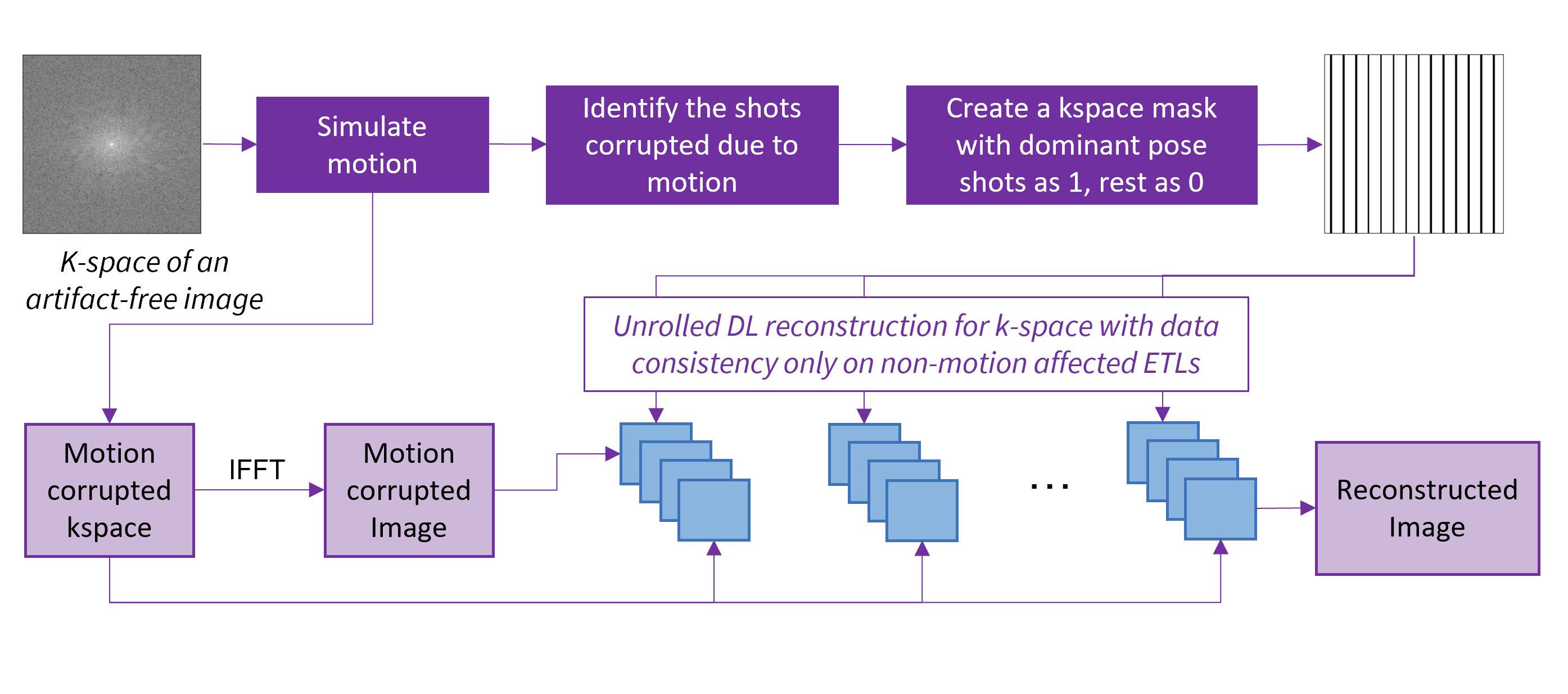
Correction: An unrolled DL-based reconstruction model has been trained to fill missing k-space lines (Fig. 2).
Training: The model is trained on motion-simulated data, for which the corrupt regions of the k-space are known. The motion corrupt image obtained from the IFFT of the motion-simulated k-space is fed to the model. The output of the model uses data consistency to retain good acquired data, while motion corrupted parts are updated. The loss is computed based on the SSIM and MAE of the predicted motion corrected image w.r.t. the ground truth. Sometimes, motion corrupt lines may fall near the center of the k-space and this may cause contrast changes that cannot be corrected for by the DL. For those cases, a different DL model with an additional input of the entire k-space was trained.
Inference: During inference for data acquired with motion, the detection module is triggered to detect motion-corrupt parts of k-space. The IFFT of the dominant pose k-space is fed to the model (along with the full k-space). The data consistency is applied using the binary mask obtained from the detection module. The output is the motion corrected image obtained from the dominant pose during the scan and is processed through standard reconstruction pipeline.
The overall flowchart for the motion correction algorithm proposed has been outlined in Fig. 1.
RESULTS AND DISCUSSION
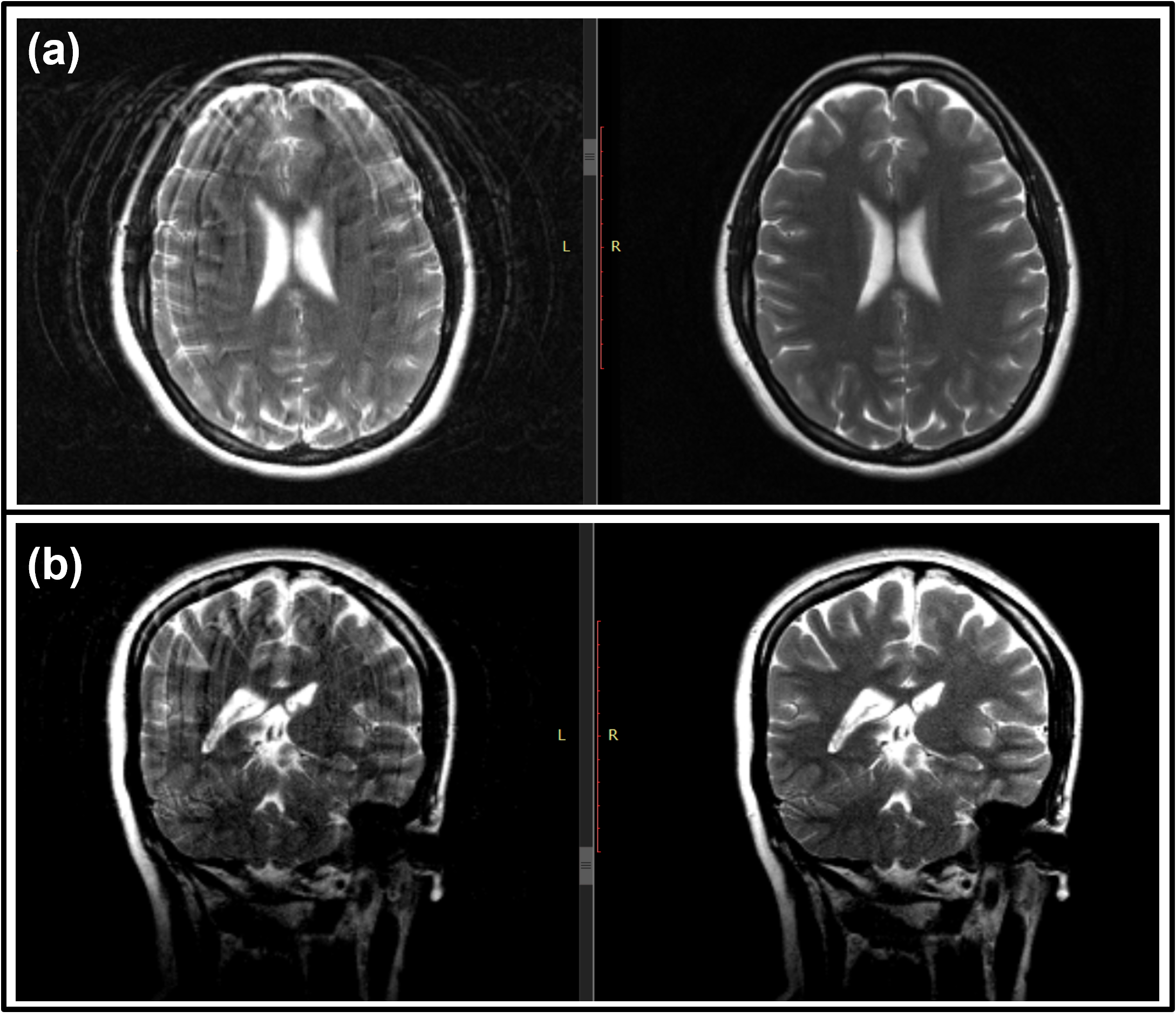
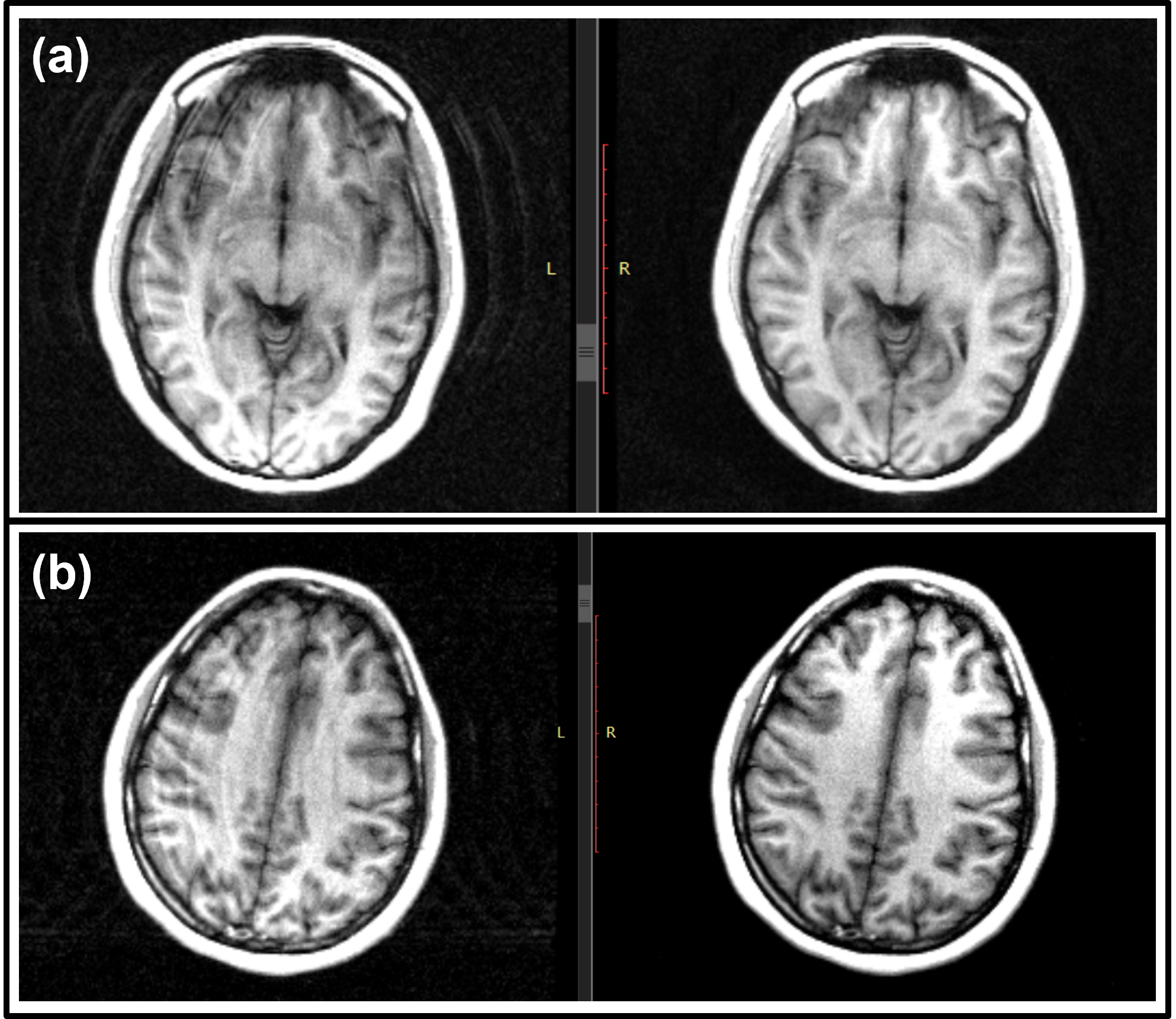
The proposed method has been evaluated on eight volunteers on a GE 1.5T MR scanner for sequences: T2/T1 FLAIR/FSE in brain and spine. The volunteers were given a range of motions to perform, from nodding and shaking of the head to imitating coughing, sneezing, swallowing, etc. The exact time to perform these actions was not dictated to the volunteer and they were free to move in an uninstructed way. We see substantial motion artifact reduction using the proposed method (Fig. 3,4). The acquisition parameters have been mentioned in the respective figure titles.CONCLUSION
The proposed strategy to correct for motion artifacts in 2D acquisitions does not rely on an accurate prediction of motion parameters. Any method to detect motion including camera, data relationships or navigators could be used to only detect motion without estimating motion. This eliminates errors that propagate due to inaccurate estimation of motion parameters and also makes it possible to correct non-rigid motion. For cases where a dominant pose cannot be ascertained due to continuous motion, the detection strategy can be implemented on the fly to acquire additional data in PROMO[6] fashion.Acknowledgements
No acknowledgement found.References
[1] Haskell, Melissa W., et al. "Network Accelerated Motion Estimation and Reduction (NAMER): Convolutional neural network guided retrospective motion correction using a separable motion model." Magnetic resonance in medicine 82.4 (2019): 1452-1461.
[2] Jansen, Isabelle Heukensfeldt, et al. “A deep network for continuous motion detection during MRI scanning.”
[3] Brada, Rafael, et al. “Perceptual motion scoring: An algorithm for automated detection and grading of MRI motion artifacts.”
[4] Polak, Daniel, et al. "Motion guidance lines for robust data consistency–based retrospective motion correction in 2D and 3D MRI." Magnetic Resonance in Medicine 89.5 (2023): 1777-1790.
[5] Singh, Nalini M., et al. "Data Consistent Deep Rigid MRI Motion Correction." arXiv preprint arXiv:2301.10365 (2023).
[6] White, Nathan, et al. "PROMO: real‐time prospective motion correction in MRI using image‐based tracking." Magnetic Resonance in Medicine: An Official Journal of the International Society for Magnetic Resonance in Medicine 63.1 (2010): 91-105.
[7] Brada, Rafi, et al. "Towards motion-robust MRI autonomous motion timing and correction during MR scanning using multi-coil data and a deep-learning neural network." Proc. ISMRM Twenty Seventh Annual Meeting. 2019.
Figures