2640
Development of Cervical Spine Mimicking Phantom for Diffusion MRI Near Metal1Division of Neuroimaging Research, Barrow Neurological Institute, Phoenix, AZ, United States
Synopsis
Keywords: Artifacts, Phantoms, Diffusion, Metal, Spine
Motivation: Diffusion-MRI (dMRI) is increasingly used to evaluate neurological disorders and injuries of the spinal cord. Unfortunately, high-quality dMRI for post-surgical evaluation of the spinal cord is often limited due to the distortion artifacts from metal implants.
Goal(s): The goal of this work is to assist in the development of novel imaging protocols to overcome this challenge.
Approach: To do this, a cervical spine phantom was developed to replicate the spine’s geometric and MRI properties along with the image artifacts generated from metal implants.
Results: Preliminary data demonstrated that the model is helpful for visualizing and developing novel dMRI protocols near metal implants.
Impact: The proposed cervical spine phantom, designed to characterize the dMRI performance of the spinal cord post-surgery, including artifacts from metallic implants, is potentially helpful for developing novel imaging techniques for post-surgical spinal cord injuries.
Introduction
Diffusion-MRI (dMRI) is increasingly used to evaluate neurological disorders and injuries to the spinal cord1-2. It has been used as a pre-surgical planning guide and has shown potential as a biomarker for post-surgical recovery3-4. However, the uses of dMRI for post-surgery spinal cord recovery have been limited due to the metal implants often required for surgical decompression. The presence of these implants generates substantial magnetic inhomogeneities, causing susceptibility-related distortion artifacts and affecting the visualization of the spinal cord near the implanted area.Even without implants, spinal cord dMRI is challenging. As such, several methods have been proposed to improve the quality of spinal cord dMRI, including multi-shot EPI (ms-EPI), PROPELLER, and single-shot TSE (ss-TSE) with reduced field-of-view5-8. To facilitate the development and validation of novel dMRI techniques, 3D-printed spines or specifically prepared diffusion phantoms have been proposed9-12. However, these phantoms either lacked MR signals11-12, required materials not readily accessible12-18, or used materials that lacked stability over time11. In this work, to assist the development of post-surgical spine imaging protocol, we developed a spine-mimicking, geometrically accurate phantom with more realistic susceptibility variations to replicate spinal cord dMRI artifacts near metal. The materials for this phantom are easy to acquire at a relatively low cost. The utility of the phantom was demonstrated with standard-of-care ms-EPI, a recently proposed ss-TSE,8 and PROPELLER6 for DWI and DTI imaging.
Methods
Figure 1 shows the in-house prepared cervical spine phantom. The titanium anterior cervical plate with four screws (Depuy, IN, USA) was fixed to the 3D-printed spine model (SurgiSTUD, AZ, USA) at C4-C5. The vertebrae are porous, allowing them to be filled with solution to produce an MR signal. The spine canal was filled with a removable micro-fiber bundle (HQ Imaging, Loerrach, Germany) and a solution to mimic the spinal cord and CSF, respectively. The model was submerged into a sucrose agarose gel to minimize magnetic field inhomogeneities from air-phantom interfaces.Data were acquired on a Phillip 3.0-T Ingenia scanner using ms-EPI, ss-TSE, and PROPELLER in one sagittal and two transverse planes - at the middle (C4) and 50mm (C7) away from the metal implants. All scans were acquired with 1.5-mm resolution, 4-mm slice thickness, 600 s/mm2 b-factor value (and 50 s/mm2 for ss-TSE), and TR=2s, TE=50/109/103 ms for ms-EPI/ss-TSE/PROPELLER. The ADC maps were generated for each scan. The sagittal scans were repeated with DTI for FA calculation. T2-weighted images were obtained for anatomical reference.
Results and Discussion
Figure 2 shows the reference T2-weighted images of the cervical spine phantom. The images displayed a similar structure to in-vivo spine images, providing helpful visualization of the spinal cord near metal implants. The distortion artifacts were observed in DW images near the implants and became less visible further away from the metal. Note that the distortion of the spinal cord in EPI was minimized in ss-TSE and PROPELLER.Figure 3 shows the dMRI results (b0, trace, ADC, and FA map) at the central plane of the spine phantom. Image distortion was visible in ms-EPI near the implants and extended toward the spinal cord, creating severe geometric distortion. The susceptibility artifacts were still visible but were greatly reduced with ss-TSE and PROPELLER due to the reduced sensitivity to the phase errors. Furthermore, the distortion of the spinal cord was nearly eliminated in ss-TSE and PROPELLER, which is typically the spinal cord studies’ target. The mean ADC of the spinal cord were 1.08±0.08 (ms-EPI), 1.11±0.05 (ss-TSE), and 1.20±0.07 10-3 mm2/s (PROPELLER), respectively, which agree with the literature value of the spinal cord diffusivity. The mean FA values within the same ROIs were 0.484±0.042, 0.495±0.04, and 0.449±0.047, respectively. The stimulated artifact level, resulting image quality, and quantitative estimates were close to those results in a previous patient DWI study8 with TSE and multispectral imaging (MSI) technique, validating the design of this phantom.
Conclusion
Imaging the spinal cord post-surgery is challenging due to the metallic implant-induced image artifacts. In this work, a spine phantom was designed to characterize the dMRI performance of the spinal cord with readily available materials and easy preparing procedures. The proposed model demonstrated different compartments and artifacts observed in standard T2 and DW spinal cord imaging with anterior cervical implants. This model is potentially helpful for developing novel imaging techniques for post-surgical spinal cord injuries, as well as systematically testing the effect of different implants on the performance of these sequences. The next step includes the application of different types of spinal implants and the refinement of the model accuracy in reproducing the diffusion measurements, contrast, and artifacts in spine MRI.Acknowledgements
This work is supported by Barrow Neurological Foundation.
References
[1] D. N. Loy, H. K. Joong, M. Xie, R. E. Schmidt, K. Trinkaus, and S. K. V. Song, “Diffusion tensor imaging predicts hyperacute spinal cord injury severity,” J Neurotrauma, vol. 24, no. 6, pp. 979–990, Jun. 2007, doi: 10.1089/neu.2006.0253.
[2] L. N. Tanenbaum, “Clinical Applications of Diffusion Imaging in the Spine,” Magnetic Resonance Imaging Clinics of North America, vol. 21, no. 2. pp. 299–320, May 2013. doi: 10.1016/j.mric.2012.12.002.
[3] J. Berman, “Diffusion MR Tractography As a Tool for Surgical Planning,” Magnetic Resonance Imaging Clinics of North America, vol. 17, no. 2. pp. 205–214, May 2009. doi: 10.1016/j.mric.2009.02.002.
[4] A. F. Choudhri, M. T. Whitehead, P. Klimo, B. K. Montgomery, and F. A. Boop, “Diffusion tensor imaging to guide surgical planning in intramedullary spinal cord tumors in children,” Neuroradiology, vol. 56, no. 2, pp. 169–174, Feb. 2014, doi: 10.1007/s00234-013-1316-9.
[5] G. McGibney, M. R. Smith, S. T. Nichols, and A. Crawley, “Quantitative evaluation of several partial fourier reconstruction algorithms used in mri,” Magn Reson Med, vol. 30, no. 1, pp. 51–59, 1993, doi: 10.1002/mrm.1910300109.
[6] K. M. Koch, S. Bhave, S. S. Kaushik, et al. “Multispectral diffusion-weighted MRI of the instrumented cervical spinal cord: A preliminary study of 5 cases,” Eur Spine J, 2019, doi: 10.1007/s00586-019-06239-z.
[7] B. J. Wilm, J. Svensson, A. Henning, K. P. Pruessmann, P. Boesiger, and S. S. Kollias, “Reduced field-of-view MRI using outer volume suppression for spinal cord diffusion imaging,” Magn Reson Med, vol. 57, no. 3, pp. 625–630, 2007, doi: 10.1002/mrm.21167.
[8] Z Li, M. B. Ooi, R. K.J. Murphy, J. P. Karis, R. D. Dortch. “Diffusion-weighted MRI of the spinal cord near metal implants: A rapid TSE approach with multispectral imaging and reduced field of view,” Proceedings of the 31st ISMRM annual meeting, 2023;1156.
[9] E. M. de Souza, E. T. Costa, and G. Castellano, “Phantoms for diffusion-weighted imaging and diffusion tensor imaging quality control: A review and new perspectives,” Research on Biomedical Engineering, vol. 33, no. 2. Brazilian Society of Biomedical Engineering, pp. 156–165, Jun. 01, 2017. doi: 10.1590/2446-4740.07816.
[10] I. Drobnjak, P. Neher, C. Poupon, and T. Sarwar, “Physical and digital phantoms for validating tractography and assessing artifacts,” Neuroimage, vol. 245, Dec. 2021, doi: 10.1016/j.neuroimage.2021.118704.
[11] S. Tounekti et al., “Metal Artifact Reduction Around Cervical Spine Implant Using Diffusion Tensor Imaging at 3T: A Phantom Study,” 2023, doi: 10.21203/rs.3.rs-2665952/v1.
[12] J. Rausch, M. Ruttorf, L.R. Schad, F.G. Zoellner. “Implementation of a diffusion tensor imaging phantom of the lumbar spinal cord,” Proceedings of the 32nd ESMRMB, 2015, S465-467.
[13] D. Mitsouras et al., “Three-dimensional printing of MRI-visible phantoms and MR image-guided therapy simulation,” Magn Reson Med, vol. 77, no. 2, pp. 613–622, Feb. 2017, doi: 10.1002/mrm.26136.
[14] J. Qiu et al., “Constructing Customized Multimodal Phantoms Through 3D Printing: A Preliminary Evaluation,” Front Phys, vol. 9, Apr. 2021, doi: 10.3389/fphy.2021.605630.
[15] A. Valladares, G. Oberoi, A. Berg, T. Beyer, E. Unger, and I. Rausch, “Additively manufactured, solid object structures for adjustable image contrast in Magnetic Resonance Imaging,” Z Med Phys, vol. 32, no. 4, pp. 466–476, Nov. 2022, doi: 10.1016/j.zemedi.2022.03.003.
[16] E. Fieremans, Y. D. Deene, S. Delputte, et al. “Simulation and experimental verification of the diffusion in an anisotropic fiber phantom,” J. Magn Reson, 2008;190:189-199, doi:10.1016/j.jmr.2007.10.014.
[17] C. Poupon, B. Rieul, I Kezele, et al. “New diffusion phantoms dedicated to the study and validation of high-angular-resolution diffusion imaging (HARDI) models,” Magn Reson Med, 2008;60:1276-1283, doi: 10.1002/mrm.21789.
[18] E. Farrher, J. Kaffanke, A. A. Celik, et al. “Novel multisection design of anisotropic diffusion phantoms,” Magn Reson Imaging, 2012;30:518-526, doi: 10.1016/j.mri.2011.12.012.
Figures
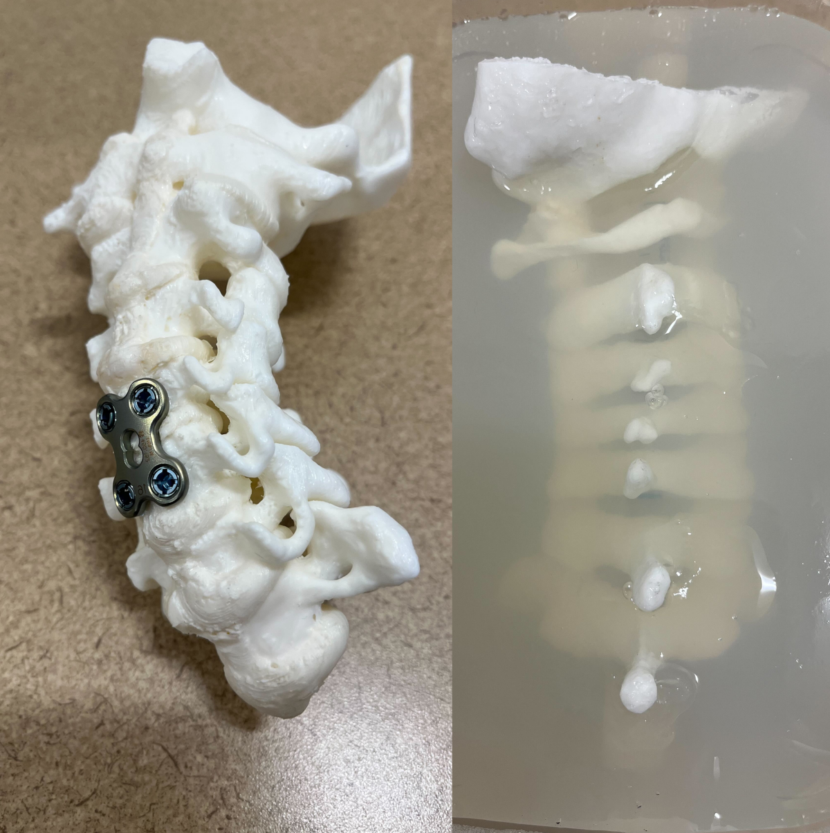
Figure 1: The cervical spine phantom developed in this study. The titanium anterior cervical plate with four screws was applied to the 3D-printed cervical spine model at level C4-C5. The model was submerged in sucrose agarose gels. A micro-fiber bundle (not visible in the picture) was inserted in the spinal canal, surrounded by water, to simulate spinal cord and CSF, respectively. The fiber bundle is removable, allowing for additional flexibility to conduct a variety of measurements.
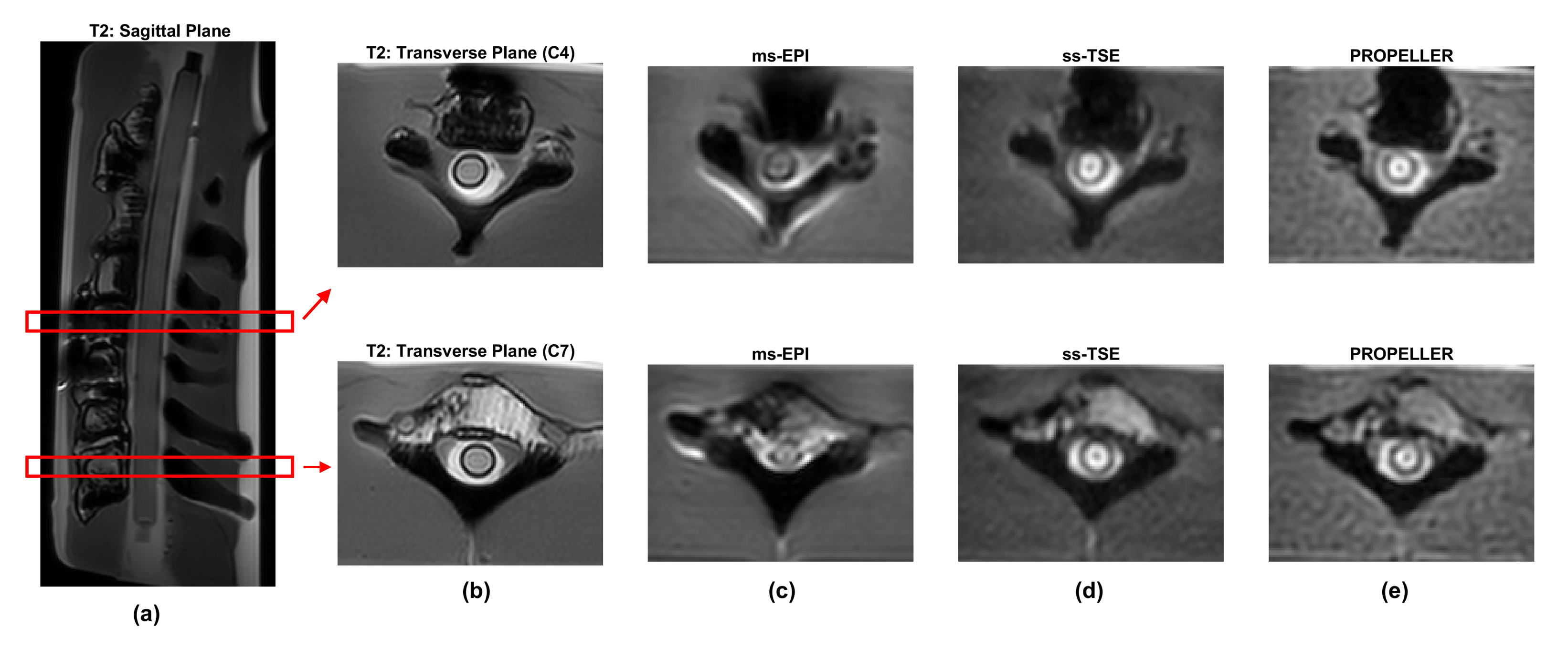
Figure 2: The reference sagittal (a) and axial (b) T2-weighted (corresponding to the red boxes in the sagittal image) and axial (c~e) DW MRI images of the cervical spine phantom. Different phantom compartments can be observed, similar to the spine structure. The distortion artifacts were observed near the implants and became less visible further away from the metal. The distortion artifacts in the spinal cord in EPI (c) were minimized in TSE (d) and PROPELLER (e).
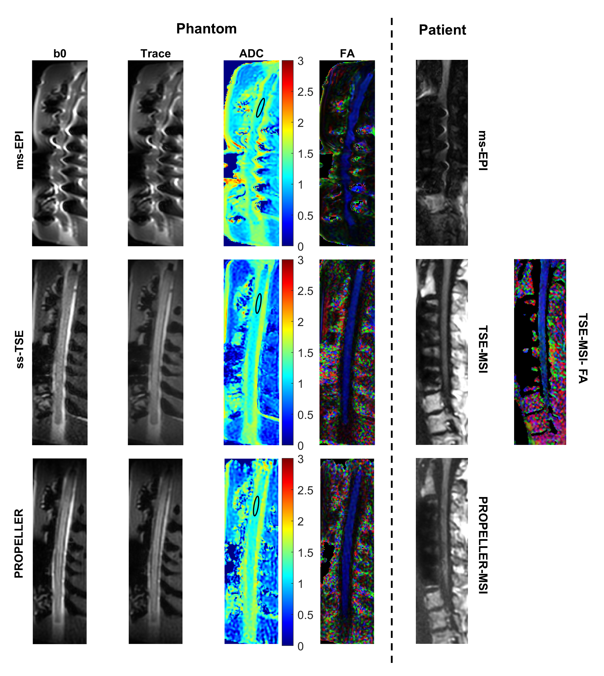
Figure 3: Sagittal images (b0, Trace, ADC, and FA map) at the central plane of the spine phantom (left). The observed image distortion on the spinal cord was visible near the implants in the ms-EPI image, while significantly reduced with ss-TSE and PROPELLER methods. The ellipses in the ADC maps indicated the ROIs for mean ADC and FA measurement. Similar distortion and signal artifact patterns were observed in the phantom and patient scans with the MSI technique. This demonstrates the phantom's ability to accurately capture relevant in vivo features for sequence testing.