2445
Motion-Corrected Distortion Reduction Around Metallic Implant Using Diffusion Tensor Imaging at 3T1Radiology, Thomas Jefferson University, Philadelphia, PA, United States, 2Radiology, Harvard Medical School, Charlestown, MA, United States, 3Neurosurgery, Thomas Jefferson University, Philadelphia, PA, United States
Synopsis
Keywords: Diffusion Acquisition, Spinal Cord, Metal Artifact, DTI, 3T
Motivation: The presence of metallic implants results in severe geometric distortion, limiting the ability of performing quantitative DTI measurement near the hardware.
Goal(s): Goal: develop an acquisition method to address metal artifact DTI on post-operative patients with metallic hardware.
Approach: A custom-built pulse sequence based on the combination of the reduced-Field-Of-View strategy and multi-shot EPI is suggested.
Results: : In-vivo and in-vitro results show that the proposed approach provides distortion-reduced and signal void at the level of the metal hardware compared to the standard method.
Impact: The ability of collecting reduced metal-artifact DTI maps around the hardware enables establishing imaging biomarkers to assess injury evolution and thoroughly evaluate microstructure changes after surgery.
Introduction
Diffusion Tensor Imaging (DTI) is key tool for in-vivo investigation of the spinal cord (SC) microstructure. It allows extraction of imaging biomarkers to assess SC integrity and evaluate pre-operative injury1. However, performing DTI on post-operative patients with metal implants results in severe geometric distortion and signal void around the hardware. Therefore, the use of DTI for post-surgery evaluation and longitudinal study remain an unexplored field and the assessment of injury is still heavily based on structural MRI techniques, clinical measures, and a surgeon’s skills. In this study, we have developed and tested an MR pulse sequence to address the technical challenges facing DTI on post-operative cases with metallic hardware.Methods
The developed method is based on the reduced Field-Of-View (rFOV) strategy and multi-shot EPI (rFOV-MS-EPI). Auto-Calibration Signal (ACS) data were used to reduce the sensitivity of EPI to subject motion and improve the image quality 2,3. Fig.1 display the diagram of the proposed pulse sequence on the left, on the right it shows the effectiveness of ACS-based correction method for addressing shot-to-shot phase variation on phantom data DTI data were collected using: the rFOV-MS-EPI and the single-shot EPI (rFOV-SS-EPI) typically used for SC scan. Geometric distortion and signal void were assessed to evaluate images and compare the two sequences on a custom-built phantom based on cervical spine model with metal implants. Asparagus was used in this phantom as a surrogate SC. Slice-by-slice ROIs were manually selected following the asparagus edge on T2-W image and the ADC maps computed from the rFOV-MS-EPI, rFOV-SS-EPI. Circularity and Eccentricity parameters were then extracted and used for pairwise comparison between the structural and diffusion data. A two-sample t-test was performed with p-value of 0.05 or less to indicate statistical significance.Additionally, this sequence was applied on two SCI participants ((F, 54Y), (M, 45Y)) with metallic implants at the C4-C6 and C3-C8 level, respectively. The experiments in this study were conducted on 3T Prisma (Siemens Healthineers, Germany). DTI Scan: The imaging parameters of the rFOV-MS-EPI were spatial resolution= 0.9×0.9×5 mm3, TR= 700 ms, TE= 60 ms, bandwidth= 1286 Hz/Pixel, Slice thickness= 5 mm, FOV = 90×32 mm2, matrix size=96×36 pixels, number of slices= 15, EPI factor = 8, concatenation = 4, number of diffusion direction = 30, scan time= 5 min 37. The imaging parameters of the rFOV-SS-EPI were spatial resolution= 0.9×0.9×5 mm3, TR= 700 ms, TE= 60 ms, bandwidth= 1166 Hz/Pixel, Slice thickness= 5 mm, FOV = 90×32 mm2, matrix size=96×36 pixels, number of slices= 15, concatenation = 4, number of diffusion direction = 30, scan time= 3 min. T2-W scan: The T2-W data were collected on two participants using the following parameters: The spatial resolution= 0.8 mm3, TR= 1500 ms, TE= 120 ms, Flip angle =120°, bandwidth= 625 Hz/Pixel, Slice thickness= 0.8 mm, FOV = 256×256 mm2, matrix size=320×320 mm2, Acceleration factor= 3, PFz= 6/8, scan time= 4 minutes. T2-w images were collected on the phantom using the following parameters: spatial resolution= 0.9×0.9×5 mm3, TR= 1500 ms, TE= 110 ms, Flip angle =120°, bandwidth= 620 Hz/Pixel, Slice thickness= 5 mm, FOV = 120×120 mm2, matrix size=128×128 mm2, number of slices= 30, phase oversampling= 30%, slice Partial Fourier = 6/8, scan time= 1:23 minutes.
Results
The rFOV-MS-EPI method provided distortion-free images of the phantom at the level of the hardware (zoomed green box, Fig.2). In addition, the suggested approach produced significantly reduced geometric distortion in Circularity (p < 0.005) and Eccentricity (p < 0.005) measurements compared to the conventional rFOV-SS-EPI. No statistically significant differences were found for these measurements between the rFOV-PS-EPI and the T2-w images (p > 0.05) (Tab.1). The computed mean diffusivity (MD) maps show that the rFOV-MS-EPI approach provides continuous cord visualization with less signal void at the level of the metal hardware compared to the standard method as indicated by arrows, allowing robust measurements at the site of the injury (Fig.3). Fig.4 shows the obtained DTI data overlayed on the T2-W image. The rFOV-SS-EPI data suffers from severe distortion, signal loss, and cord displacement at the regions near the metal compared to the data collected using the proposed acquisition technique.Conclusion
The validity of the proposed approach to collect metal reduced DTI images on spinal model and SCI patient with metallic hardware was demonstrated by providing less geometric distortion DTI maps and smaller signal void area around the site of the metal at 3T, allowing extraction of quantitative measurement at the site of injury. These preliminary results are very promising and warrants a study on a larger group of SCI subjects with metal implants.Acknowledgements
C. M* and F. M*: These authors have contributed equally to this work.
This work was supported by the National Institute of Neurological Disorders and Stroke (NINDS) under award number R01NS111113 (Thomas Jefferson University, Philadelphia, PA).
References
1. Saksena S, Mohamed FB, Middleton DM, et al. Diffusion Tensor Imaging Assessment of Regional White Matter Changes in the Cervical and Thoracic Spinal Cord in Pediatric Subjects. J Neurotrauma. 2019;36(6):853-861. doi:10.1089/neu.2018.5826
2. Polimeni JR, Bhat H, Witzel T, et al. Reducing sensitivity losses due to respiration and motion in accelerated echo planar imaging by reordering the autocalibration data acquisition. Magn Reson Med. 2016;75(2):665-679. doi:10.1002/mrm.25628
3. Bilgic B, Chatnuntawech I, Manhard MK, et al. Highly accelerated multishot echo planar imaging through synergistic machine learning and joint reconstruction. Magn Reson Med.
Figures
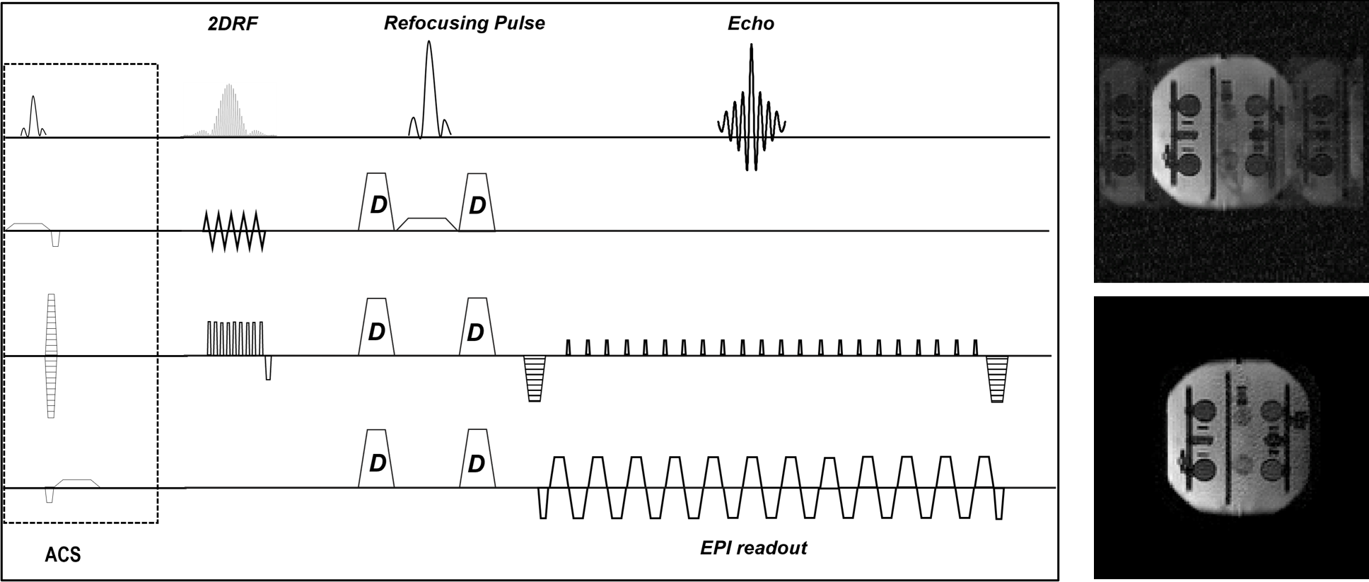
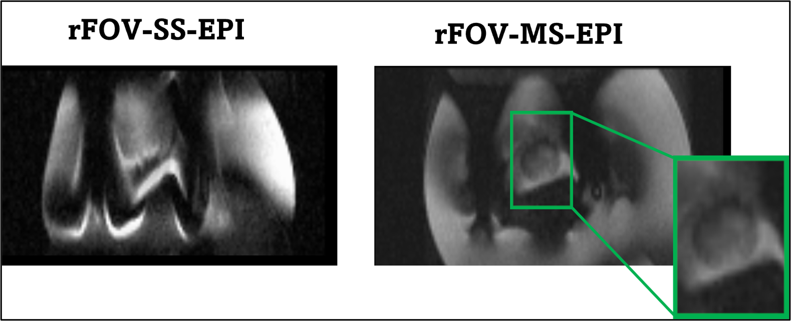

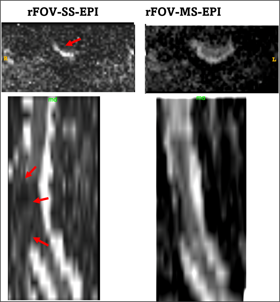
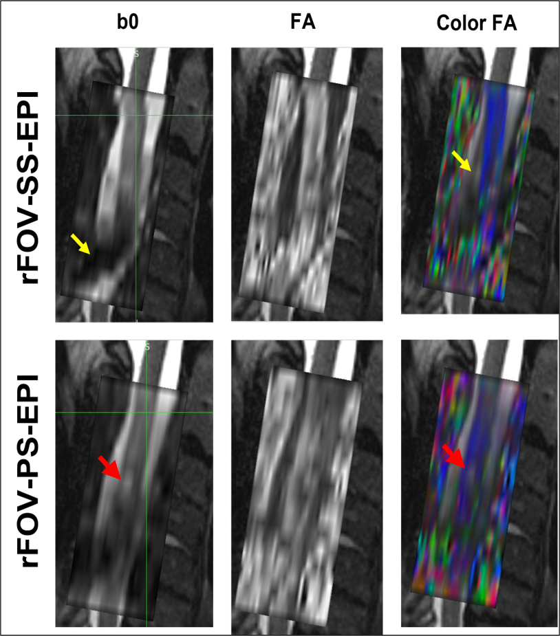
Fig.4: The rFOV-SS-EPI DTI data suffers from severe distortion and cord displacement (yellow arrows) compared to the proposed technique. The lesion underlying the loss of anisotropy is better seen on the PS-EPI and the location is anatomically correct with respect to the T2(red arrows).