2142
Efficient and High-Quality Ray Marched Glyphs for Diffusion Tensor Imaging1Department of Intelligent Systems Engineering, Indiana University, Bloomington, IN, United States, 2Department of Mathematics, National University of Colombia, Bogota, Colombia
Synopsis
Keywords: Diffusion Analysis & Visualization, Visualization, Computer Graphics, Ray Marching, Signed Distance Functions
Motivation: Traditional rendering engines represent surfaces using simpler polygons (triangles or quads). This discretization can compromise real-time performance as more polygons are required to build smoother surfaces.
Goal(s): Develop a new efficient method for building and displaying DTI-related glyphs without compromising their visual quality using continuous geometric representations.
Approach: Ray marching is a robust technique for tracing implicit surfaces using signed distance functions (SDFs). Our method uses these techniques to create representations of commonly used DTI-related glyphs.
Results: Our SDFs glyphs make it possible to define smooth surfaces in a more efficient way that allows us to visualize more objects than traditional polygon-based renderers.
Impact: By using SOTA efficient rendering algorithms for complex elements, such as DTI-related glyphs, we improved the performance of scientific visualization systems, enabling the visualization of more extensive datasets and/or multiple types of data in real-time without sacrificing visual quality.
Introduction
Diffusion tensor voxel-level information is commonly represented as ellipsoids1. Traditional rendering engines use polygons like triangles or quads to build these ellipsoids, which ties their resolution to the number of polygons used. However, increasing the amount of rendered polygons tends to decrease the number of frames per second (FPS), hurting the performance and, consequently, the real-time interactivity of the visualization. Since visualizing vast amounts of glyphs is expensive, few methods have studied the quantization and visualization of uncertainty associated with the DTI model2. Unfortunately, they all suffer from the same rendering constraints. This work proposes a novel approach that uses ray marching3 and signed distance functions (SDFs)4 to improve the visualization of DTI tensors. This method shows significant performance improvements in terms of a higher frame rate. Furthermore, the resource optimization of this approach allows the visualization of the associated uncertainty of the DTI model. These contributions are expected to serve neuroscientists in their analyses.Methods
Ray marching (or sphere tracing) is a powerful technique for tracing implicit surfaces. It generates a sequence of points that converge linearly to the first ray-surface intersection3,4. The ray is defined by the parametric equation $$$r(t)=o+td$$$, where $$$o$$$ is its origin, $$$d$$$ is its direction, and $$$t$$$ is the distance it has traveled5. The intersection point is determined by substituting $$$r(t)$$$ into an implicit surface function or signed distance function (SDF) and solving for $$$SDF(r(t))=0$$$6. The sphere tracing algorithm can then be used to find the least positive root of the SDF. This root serves as the sequence's limit point, which is defined by the recurrence equation $$$t_{i+1}=t_{i}+SDF(r(t))$$$, where $$$t_0=0$$$4. The sequence converges only if the ray intersects the surface defined by the SDF. The used function transforms a sphere into an ellipsoid since the SDF of an ellipsoid is more expensive to calculate, and the definition of a tensor ($$$T=R^{-1}\Lambda R$$$) gives us a linear transformation of any geometry. Therefore, glyph-based tensor visualization can be defined as $$$G_T=R\Lambda G$$$, where $$$R$$$ is a rotation matrix that transforms the standard basis onto the eigenvector basis, $$$\Lambda$$$ is the diagonal matrix of eigenvalues, and $$$G$$$ is the initial glyph geometry1,7,8. Then, a matrix perturbation analysis approach was selected to visualize the uncertainty as symmetrical cones9,10 using the SDF $$$d(p)=f_B(p)\cap f_C(p)$$$. By SDF properties, this intersection can be simplified to the maximum value between the two sub-SDFs11 in the expression, which then becomes $$$d(p)=\max\left(f_C(p),f_B(p)\right)$$$. Where $$$f_C(p)=\|(x,z)\|\cos{\theta}-|y|\sin{\theta}$$$ is the SDF that defines the cone, with $$$p$$$ a point $$$(x,y,z)\in\mathbb{R}^3$$$ and $$$\theta$$$ the opening angle of the cone. Additionally, $$$f_B(p)=\|\max\left(|p|-s,0\right)\|$$$ is the SDF that constraints the cone to be within the box that contains each glyph, with $$$s$$$ the size of that box.Results
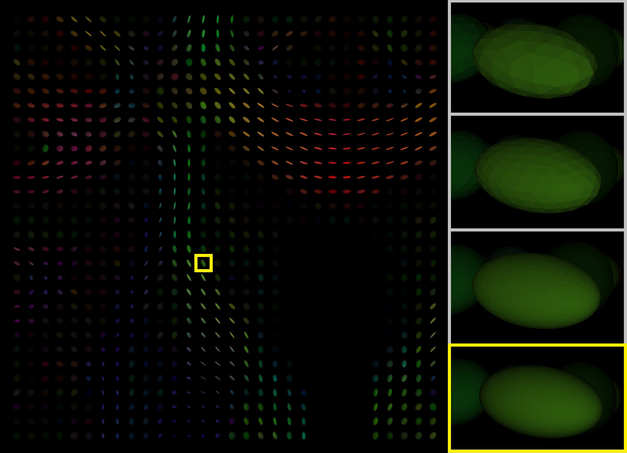
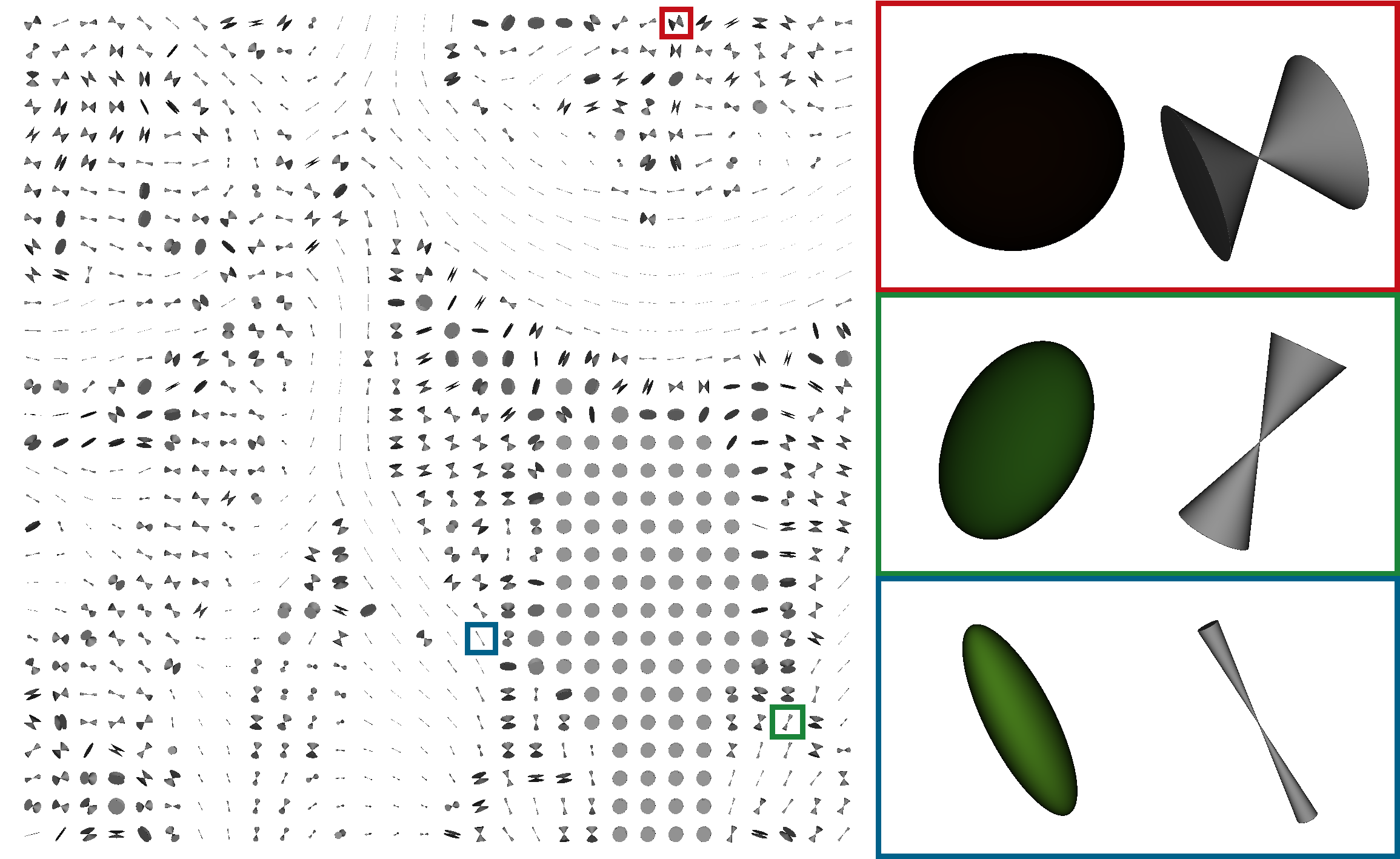
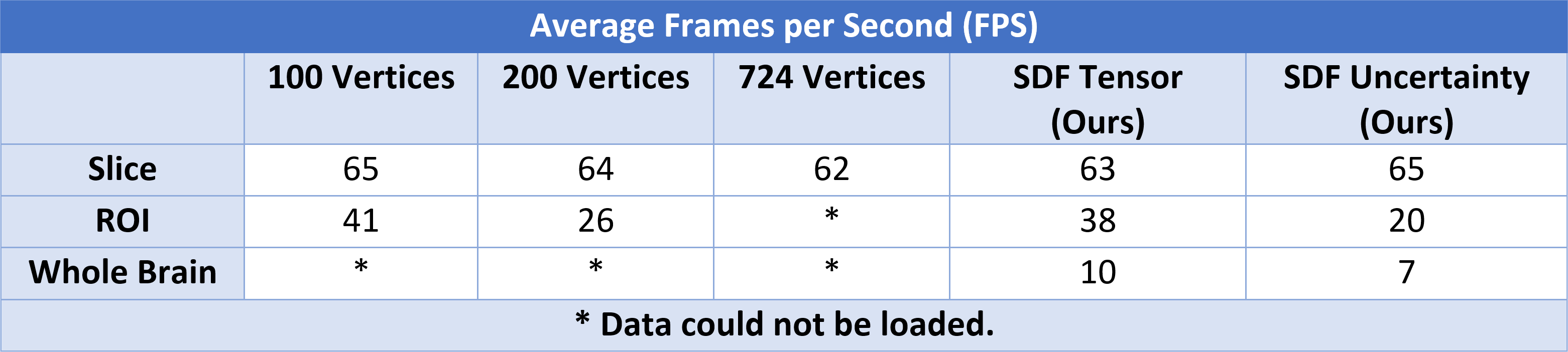
This work includes comparisons between the introduced SDF-based glyphs and traditional polygonal-based glyphs using different amounts of vertices (100, 200, 724) to account for multiple resolutions. Then, quantitative and qualitative comparisons were made. The quantitative experiment consisted of a 1-minute animation displayed on a 500x500 pixels window. It was programmed to continuously rotate a scene with several amounts of glyphs using different rendering methods. In each case, the frames per second (FPS) were measured, averaged, and compiled in Table 1. These experiments were conducted on a PC with an Intel(R) UHD Graphics 620 300 MHz CPU, 8GB RAM, and a Nvidia GeForce MX110 GT GPU with 2GB of memory. For qualitative assessment, we added Figures 1 and 2, illustrating the higher resolution of the novel SDF-based glyphs compared to the highest resolution polygonal-based glyph.Discussion
Evaluating a continuous function such as an SDF allows the definition of perfectly smooth surfaces, as seen in Figures 1 and 2. The proposed method also offers better scalability since a new glyph only adds eight vertices and only the visible pixels within the frustum are evaluated. As described, the unique nature of SDFs enables the creation of complex shapes by combining simpler primitives at a low computational cost. In addition, SDFs have unique properties that allow for inexpensive calculations of surface normals and tangents, as well as antialiasing, ambient occlusion, and shadowing.Conclusion
Overall, our experiments on consumer hardware (general-purpose desktops and laptops) illustrate the potential of ray-casting-based techniques such as sphere tracing. Our results indicate that SDF-based rendering scales better than polygon-based rendering as data grows. We expect this work to catch the attention of computer graphics researchers so the medical community can benefit from the latest advancements in that field. The method described is already in FURY12 and soon will be added to DIPY13.Acknowledgements
This work was conducted in part using the resources of the Technology for Research division of the University Information Technology Services (UITS) at Indiana University, Bloomington, IN. This work was supported by the National Institute of Biomedical Imaging and Bioengineering (NIBIB) of the National Institutes of Health (NIH) under Award Numbers R01EB027585 and R01EB017230. FURY was partly funded through NSF 1720625 Network for Computational Nanotechnology - Engineered nanoBIO Node.References
- Kindlmann G. Superquadric tensor glyphs. In Proceedings of the Sixth Joint Eurographics-IEEE TCVG conference on Visualization 2004 May 19 (pp. 147-154).
- Siddiqui F, Höllt T, Vilanova A. Uncertainty in the DTI Visualization Pipeline. In Anisotropy Across Fields and Scales 2021 (pp. 125-148). Springer International Publishing.
- Hart JC, Sandin DJ, Kauffman LH. Ray tracing deterministic 3-D fractals. In Proceedings of the 16th annual conference on Computer graphics and interactive techniques 1989 Jul 1 (pp. 289-296).
- Hart JC. Sphere tracing: A geometric method for the antialiased ray tracing of implicit surfaces. The Visual Computer. 1996 Dec;12(10):527-45.
- Shirley P. Ray tracing in one weekend. Amazon Digital Services LLC. 2018;1:4.
- Sederberg TW, Zundel AK. Scan line display of algebraic surfaces. ACM SIGGRAPH Computer Graphics. 1989 Jul 1;23(3):147-56.
- Basser PJ, Pierpaoli C. Microstructural and physiological features of tissues elucidated by quantitative-diffusion-tensor MRI. Journal of magnetic resonance. 2011 Dec 1;213(2):560-70.
- Pierpaoli C, Basser PJ. Toward a quantitative assessment of diffusion anisotropy. Magnetic resonance in Medicine. 1996 Dec;36(6):893-906.
- Basser PJ. Quantifying errors in fiber direction and diffusion tensor field maps resulting from MR noise. In5th Scientific Meeting of the ISMRM 1997 (Vol. 1740).
- Chung HW, Chou MC, Chen CY. Principles and limitations of computational algorithms in clinical diffusion tensor MR tractography. American Journal of Neuroradiology. 2011 Jan 1;32(1):3-13.
- Ricci A. A constructive geometry for computer graphics. The Computer Journal. 1973 Jan 1;16(2):157-60.
- Garyfallidis E, Koudoro S, Guaje J, Côté MA, Biswas S, Reagan D, Anousheh N, Silva F, Fox G, Contributors FU. FURY: advanced scientific visualization. Journal of Open Source Software. 2021 Aug 4;6(64):3384.
- Garyfallidis E, Brett M, Amirbekian B, Rokem A, Van Der Walt S, Descoteaux M, Nimmo-Smith I, Dipy Contributors. Dipy, a library for the analysis of diffusion MRI data. Frontiers in neuroinformatics. 2014 Feb 21;8:8.
Figures