2019
Dynamic B0 field shimming for improving pseudo-continuous arterial spin labeling at 7 Tesla1University of Oxford, Oxford, United Kingdom
Synopsis
Keywords: Arterial Spin Labelling, Arterial spin labelling
Motivation: Increased B0 inhomogeneity along the length of brain-feeding arteries at 7 Tesla is one major issue for pseudo-continuous arterial spin labeling (PCASL), which reduces the labeling efficiency, leading to loss of perfusion signal.
Goal(s): Our goal is to improve PCASL at 7 Tesla by specifically improving B0 field homogeneity of the vessels within the inversion region.
Approach: We propose a vessel-specific dynamic B0 shimming method to optimize labeling efficiency without compromising the static shim over the imaging region.
Results: Preliminary perfusion images indicate the superior performance of our proposed 3D dynamic shimming method over global or 2D-based correction methods.
Impact: Our proposed dynamic B0 shimming method demonstrates strong potential in improving the robustness and effectiveness of PCASL, allowing the high sensitivity and spatial resolution of 7T ASL to be fully utilized.
Introduction
Arterial spin labeling (ASL) has been increasingly implemented on ultra-high field systems due to the advantages offered by the improved SNR and the extended ASL tracer lifetime. However, one major issue that needs to be considered is the increased B0 inhomogeneity along the length of brain-feeding arteries, which significantly reduces the labeling efficiency, leading to loss of perfusion signal1. In this work, we demonstrate a B0 field inhomogeneity correction method aimed at improving pseudo-continuous ASL (PCASL) at 7 Tesla by specifically targeting B0 field homogeneity at the location of the feeding arteries within the inversion region. Our approach relies on dynamic B0 shimming2, which involves the application of extra constant gradients during the labeling period.Methods
Vessel-specific dynamic B0 shimmingThe estimation of the required amplitude of gradients (ΔGx, ΔGy, ΔGz) and the residual global frequency offset ΔfGlob for vessel-specific dynamic B0 shimming can be derived from 3D field maps that cover the labeling region by solving:
$$\frac{\gamma}{2\pi}\begin{bmatrix}PX_{1}&PY_{1}&PZ_{1}&-1 \\ PX_{2}&PY_{2}&PZ_{2}&-1 \\ PX_{3}&PY_{3}&PZ_{3}&-1 \\ &⋮ \\ PX_{n}&PY_{n}&PZ_{n}&-1 \end{bmatrix}\begin{bmatrix}∆G_{x} \\ ∆G_{y} \\ ∆G_{z} \\ 2\pi\cdot ∆f_{Glob}/\gamma \end {bmatrix}=\begin{bmatrix}- ∆f_{1} \\- ∆f_{2}\\- ∆f_{3} \\⋮\\- ∆f_{n} \end{bmatrix}$$
where (PXi, PYi, PZi) and Δfi are the location of the ith vessel voxel within the shimming region and the corresponding frequency offset, respectively. Since inversion efficiency is only affected by B0 homogeneity where blood is passing through the inversion region, we limited the shimming region to small ROIs within the arteries at the level of the labeling region, allowing much more targeted optimization than shimming the entire labeling region. Dynamic B0 shimming can also be performed in 2D (ignoring through-plane B0 variations). In such a condition, no additional gradient is applied along the z-direction.
In vivo data acquisition
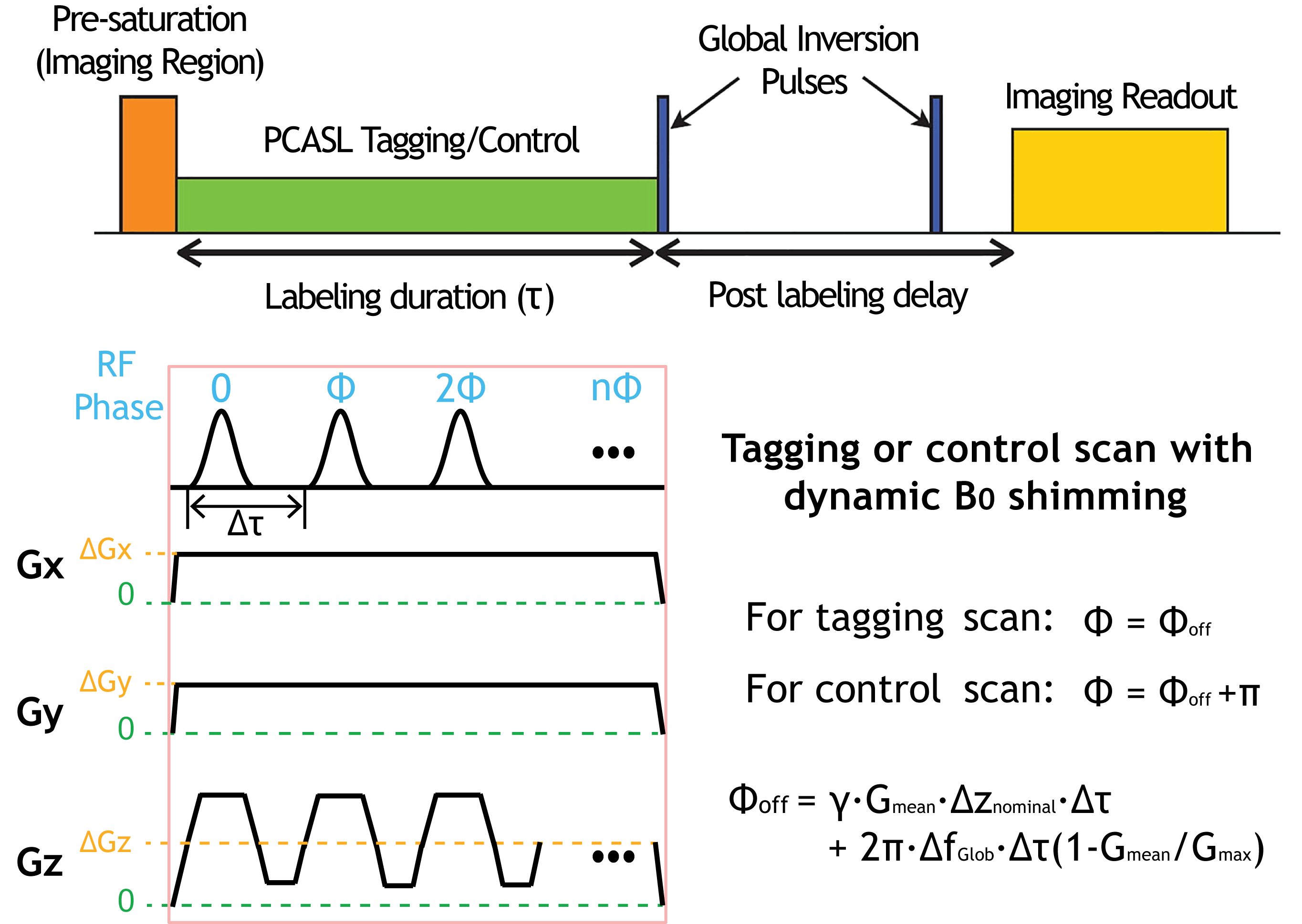
The proposed PCASL sequence diagram with a dynamic B0 shimming is illustrated in Figure 1. Data were acquired on a 7T Siemens Magnetom Plus scanner equipped with an 8Tx/32Rx head coil. A time-of-flight sequence was performed to select a labeling plane. B1-mapping was performed using 3DREAM3 to calibrate the transmit voltage and determine a compensation factor for the lower B1 at the labeling plane. PCASL with an EPI readout was performed using low-SAR optimized parameters4, with the application of 2D and 3D dynamic shimming, an OES-based5, and global offset correction methods, in addition to an uncorrected acquisition. Field maps were acquired within five slices that cover the inversion region, with a 2mm slice thickness, using an identical static shimming as the PCASL scan.
Results
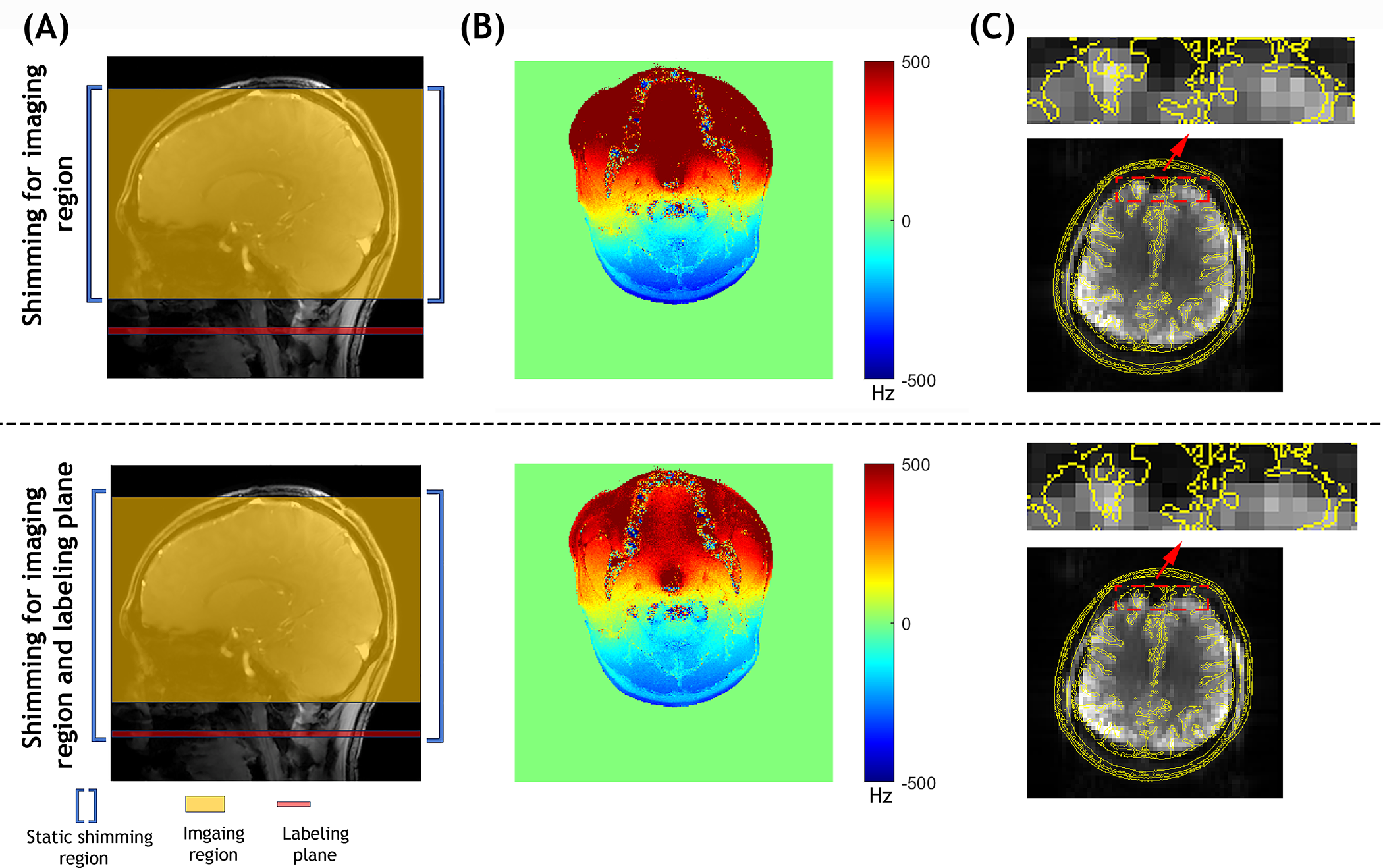
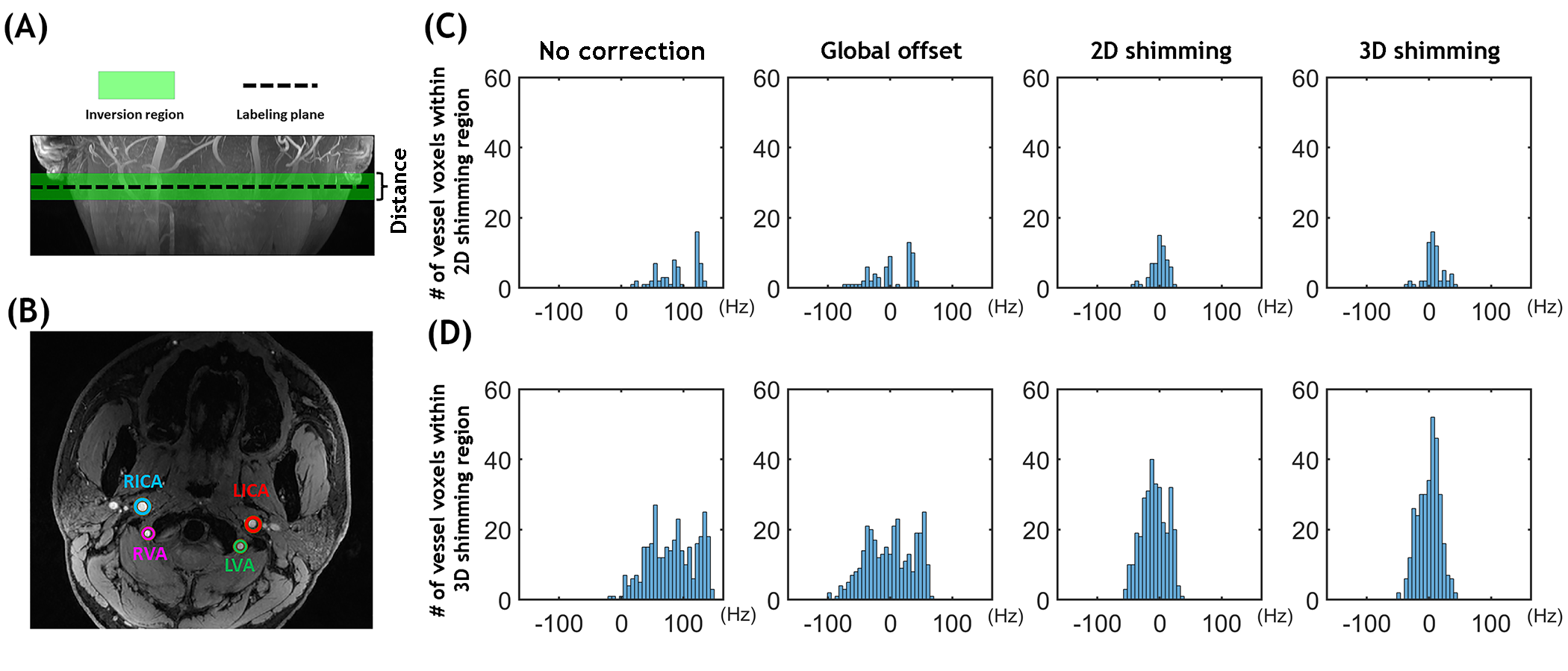
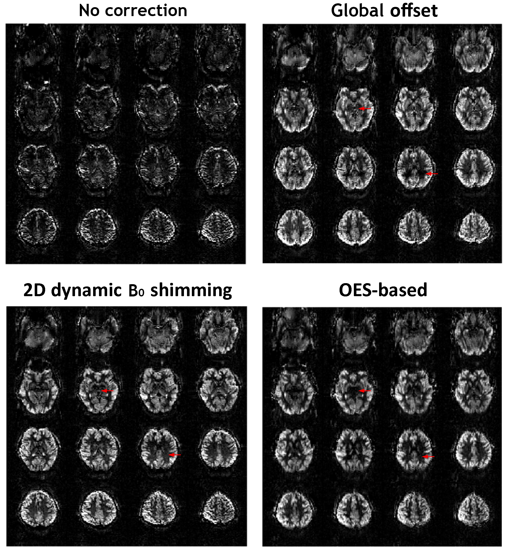
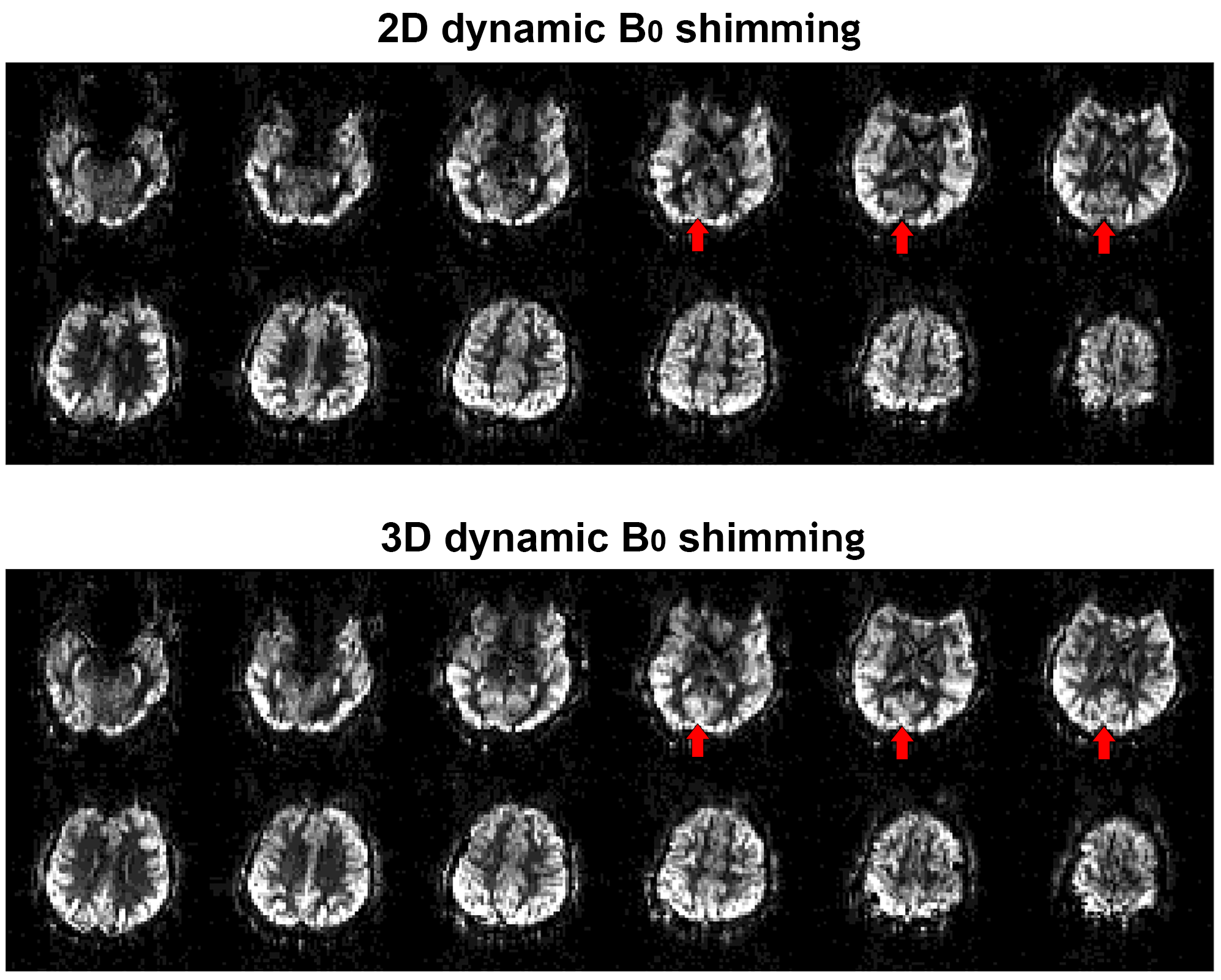
Figure 2A compares two different static B0 shimming set-ups. Figure 2B shows the field maps at the labeling with the two approaches. The typical shimming approach for PCASL at 7T that covers both the imaging region and labeling plane is suboptimal for the imaging readout and background suppression pulses. This is shown in Figure 2C, where EPI images from the shimming setting that covers only the imaging region show less distortion, which we used in subsequent experiments. Figure 3A illustrates the spatial relationship between the inversion region and the labeling plane in PCASL, along with four main brain-feeding arteries labeled within the labeling plane (Figure 3B). 2D and 3D dynamic shimming ROIs were chosen within the vessels in the labeling plane and inversion region, respectively. The resulting histograms, as depicted in Figure 3C and 3D, illustrate the frequency offset distribution of the target vessels using both shimming methods. These histograms clearly demonstrate that both techniques are effective in significantly alleviating off-resonance. Figure 4 compares the perfusion images obtained with different off-resonance correction methods. The perfusion signal loss can be easily observed in the images due to off-resonance from the uncorrected acquisition, which was significantly recovered after applying the global offset correction, 2D shimming, and OES-based correction methods. Nevertheless, the signal intensity in some pixels using the global offset and OES-based correction methods remains lower than that achieved with 2D shimming (red arrows). Figure 5 compares the perfusion images from PCASL with 2D and 3D dynamic shimming methods. While both approaches yielded good whole-brain perfusion maps, enhanced perfusion signal was observed in the posterior circulation when using the 3D shimming method.Discussion and Conclusion
Our proposed dynamic B0 shimming approach is fast and not only addresses the in-plane linear B0 variation but also accounts for B0 variation in the through-plane direction. Preliminary perfusion images indicate the superior performance of our 3D shimming method over global or 2D-based correction methods. It is worth mentioning that our shimming method improves B0 homogeneity within the vessels, not throughout the whole inversion region, which allows a more targeted optimization than a general dynamic shim.Acknowledgements
This work was enabled by a Sir Henry Dale Fellowship jointly funded by the Wellcome Trust and the Royal Society (220204/Z/20/Z). The Wellcome Centre for Integrative Neuroimaging is supported by core funding from the Wellcome Trust (203139/Z/16/Z).References
1. Saïb, Gaël, Alan P. Koretsky, and S. Lalith Talagala. "Optimization of pseudo‐continuous arterial spin labeling using off‐resonance compensation strategies at 7T." Magnetic Resonance in Medicine 87.4 (2022): 1720-1730.
2. Stockmann, Jason P., and Lawrence L. Wald. "In vivo B0 field shimming methods for MRI at 7 T." NeuroImage 168 (2018): 71-87.
3. Ehses, Philipp, et al. "Whole‐brain B1‐mapping using three‐dimensional DREAM." Magnetic Resonance in Medicine 82.3 (2019): 924-934.
4. Joseph G. Woods, Mark Chiew, and Thomas W. Okell. "Minimizing SAR for SNR-Efficient Pseudo-Continuous Arterial Spin Labeling at 7T" ISMRM 2023
5. Berry, Eleanor SK, Peter Jezzard, and Thomas W. Okell. "Off-resonance correction for pseudo-continuous arterial spin labeling using the optimized encoding scheme." NeuroImage 199 (2019): 304-312.
6. Marques, José P., et al. "MP2RAGE, a self bias-field corrected sequence for improved segmentation and T1-mapping at high field." NeuroImage 49.2 (2010): 1271-1281.
Figures